
Biologically-Inspired Neural Network for Walking Stabilization of
Humanoid Robots
Guilherme Barros Castro
1
, Kazuya Tamura
2
, Atsuo Kawamura
2
and André Riyuiti Hirakawa
1
1
Department of Computer Engineering and Digital Systems, University of São Paulo, São Paulo, Brazil
2
Department of Electrical and Computer Engineering, Yokohama National University, Yokohama, Japan
Keywords: Biologically-Inspired Neural Network, Humanoid Robots, Computational Intelligence, Walking
Stabilization.
Abstract: In order to accomplish desired tasks, humanoid robots may have to deal with unpredicted disturbances,
generated by objects, people and even ground imperfections. In some of these cases, foot placement is
critical and cannot be changed. Furthermore, the robot has to conduct the actions planned meanwhile
stabilizing its walking motion. Therefore, we propose a Biologically-inspired Neural Network (BiNN) to
stabilize the walking motion of humanoid robots by ankle joint control, which minimally affects the current
movements of the robot. In contrast to other neural networks, which only generate walking patterns, the
BiNN is adaptive, as it compensates disturbances during the robot motion. Moreover, the BiNN has a low
computational time and can be used as a module of other control methods. This approach was evaluated
with Webots simulator, presenting improvements in the compensation of an external force in regard to its
magnitude and duration.
1 INTRODUCTION
Humanoid robots are expected not only to act in the
same environment and to perform similar tasks as
humans, but also to act in dangerous environments,
such as those present in catastrophe or rescue scena-
rios, and to perform tasks that humans are not able
to, such as lifting heavy weights. In these situations,
humanoid robots may need to avoid objects and
people and deal with irregular ground, all of which
may generate disturbances and affect its balance.
There are two main alternatives to compensate
external disturbances and stabilize robot motion:
stepping (Stephens and Atkeson, 2010; Luo et al.,
2015), and postural control (Sano and Furusho,
1990; Stephens, 2007; Lee and Goswami, 2012;
Lober, Padois and Sigaud, 2014; Maalouf et al.,
2015). Stephens and Atkeson (2010) state that
humanoid robots are able to sustain larger
disturbances by stepping. However, in some
situations the robot may have to perform specific
foot placements due to environment constraints. In
these cases, postural control is the best alternative to
guarantee stability without violating any constraints.
Different strategies were proposed to achieve
postural control, which can be classified into two
categories: whole body control (Lee and Goswami,
2012; Lober, Padois and Sigaud, 2014) and ankle
joint control (Sano and Furusho, 1990; Stephens,
2007; Maalouf et al., 2015). Whilst in the whole
body control strategy all actuators can be used to
balance the robot motion, strategies based on ankle
joint control stabilize the motion only with ankle
actuators. In spite of the effectiveness of the former
control method against more severe disturbances, as
shown in (Stephens, 2007), this research focuses on
ankle joint control, for its simplicity and efficiency.
By controlling only the ankle joints it is possible
to compensate significant disturbances without
changes to other joint trajectories, not interfering
with the upper limb actions currently being executed
or previously planned by the robot. Moreover, ankle
joint control can be used with other control
approaches, being activated in the cases that external
disturbances are moderate.
Sano and Furusho (1990) achieved natural
dynamic walking by controlling the ankle torque of
the supporting leg and, thus, manipulating the robot
angular momentum. Stephens (2007) analyses the
disturbance compensation capacity based on the
current state of humanoid robots which adopt the
ankle stabilization strategy. Maalouf et al. (2015)
proposed a model-free approach for humanoid robot
96
Castro G., Tamura K., Kawamura A. and Hirakawa A.
Biologically-Inspired Neural Network for Walking Stabilization of Humanoid Robots.
DOI: 10.5220/0006138700960104
In Proceedings of the 9th International Conference on Agents and Artificial Intelligence (ICAART 2017), pages 96-104
ISBN: 978-989-758-220-2
Copyright
c
2017 by SCITEPRESS – Science and Technology Publications, Lda. All rights reserved
stabilization, showing improved results in
comparison to the model-based approach presented
in (Stephens, 2007). Nevertheless, the authors only
investigated push recovery situations in which the
robot was standing still, and their control objective
was to maintain an upright position. Both aspects do
not allow the direct application of the approach to
stabilize a walking motion.
In this paper, we propose a Biologically-inspired
Neural Network (BiNN) to stabilize the walking
motion of humanoid robots. The approach proposed
is modular, i.e., can be used in conjunction with
walking pattern generation and stepping approaches,
and has a low computation time, which is relevant to
ensure real-time control. We investigate here the
stability of NAO humanoid robot in regard to lateral
disturbances (y-direction) during a walking motion,
evaluating with simulations the BiNN capacity of
stabilizing different external forces as well as the
computation time of each control step.
In contrast to Artificial Neural Networks
(ANNs), whose focus is on the learning aspect of
biological neural networks, the BiNN focuses on
determining its structure and parameters in order to
achieve a desired behaviour. Whereas ANNs with
different training methods were proposed to estimate
humanoid robot models for control purposes (Liu
and Li, 2003; Rai et al., 2012; Sun et al., 2016), the
BiNN proposed does not adopt previous training and
does not have a convergence period.
However, other characteristics of the BiNN
proposed resemble biological neural networks, such
as: inhibitory synapses, which represent negative
influences between neurons; sensorial inputs, which
resemble biological sensorial receptors; and different
activation functions, as in the different types of
biological neurons (Kandel et al., 2012).
Works related to BiNNs were proposed to
control different types of robots, as surveyed by Yu
et al. (2014). In addition to the robots presented in
(Yu et al., 2014), which adopt BiNNs with an
oscillatory behaviour inspired by the biological
Central Pattern Generator (CPG) of humans,
Nichols, Mcdaid and Siddique (2013) and
Helgadóttir et al. (2013) proposed other BiNNs to
control the motion of wheeled robots. Different
BiNNs have different network structures, neuron
models, which comprise membrane potential
(activation) and neuron output determination, types
of synapses and neural adaptation mechanisms.
BiNNs for humanoid robot control, such as those
proposed by Taga, Yamaguchi and Shimizu (1991),
Cao and Kawamura (1998), Endo et al. (2008) and
Saputra et al. (2016), focus on the walking pattern
generation part of the robot motion, not being able to
adaptively compensate external disturbances.
Contrary to these approaches, the BiNN proposed
does not focus on the walking pattern generation, but
on the walking stabilization.
2 HUMANOID ROBOT WALKING
STABILIZATION
Stable walking of a humanoid robot can be defined
as the realization of any walking motion in which
the humanoid robot achieves the final position
desired without falling down. In order to guarantee
the dynamical balance of the walking motion, the
Zero Moment Point (ZMP) of the robot must remain
inside its support polygon during its entire motion
(Vukobratović, Borovac and Potkonjak, 2006).
Thereby, ZMP is the point at which the resultant
ground reaction force acts, whereas the support
polygon is the projected area beneath the robot’s feet
which is formed by the convex hull of its footprints
(Vukobratović and Stepanenko, 1972). Equation (1)
represents this stability criterion for the y-direction,
which is the focus of this paper. In the equation,
represents the current ZMP, and
and
represent the upper and lower bounds of the support
polygon in the y-direction.
(1)
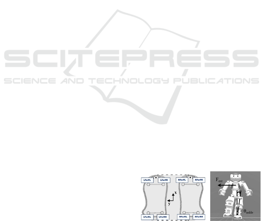
The grey area in Fig. 1a corresponds to the
support polygon of NAO robot – used in this
research – when both feet are on the ground. In the
figure, the labels (LFsrFL, LFsrFR, etc.) indicate the
position of eight Force Sensitive Resistors (FSR),
which measure resistance changes according to the
variation of the pressure applied. When only one
foot is on the ground, the support polygon
corresponds to the footprint area of that foot.
To determine the current ZMP in the y-direction,
the ZMP equation rewritten by Kajita et al. (2003)
from (Vukobratović and Stepanenko, 1972) is
Figure 1: (a) Support polygon of NAO robot. (b) Ankle
joint control.
Biologically-Inspired Neural Network for Walking Stabilization of Humanoid Robots
97
adopted, as represented by (2). In the equation,
and
represent the center of mass position in y-
and z-directions, g represents the gravitational
acceleration, and
represents the center of mass
acceleration in y-direction.
=
−
(2)
The approach presented in this paper controls the
robot ankle motors in order to control the ZMP,
guaranteeing a stable walking by satisfying the
stability criterion even in scenarios with external
disturbances. Thus, the BiNN influences the centre
of mass position and acceleration by determining the
ankle angular position
(and angular velocity
), as illustrated in Fig. 1b. The hip motors are
also controlled, but only to maintain the robot torso
vertical, reducing the overall motion range and
increasing its stability.
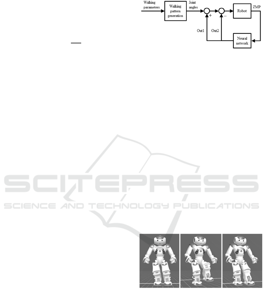
The control cycle of the method proposed is
illustrated by a block diagram in Fig. 2. The first
block, ‘Walking pattern generation’, has as inputs
the walking parameters that determine the motion
desired, such as step height, step length and walking
speed. The robot joint angles compose the outputs of
this block. The second block is the control cycle
plant, i.e., the robot. To accomplish closed loop
control, FSR measurements, such as the ZMP, are
sent as a feedback to the BiNN, which is the main
contribution of this paper. The neural network
processes this information and produces an output
with two components, one positive (Out1) and one
negative (Out2), altering the ankle and hip angles
sent as references to the robot.
3 WALKING PATTERN
GENERATION
The walking pattern generation approach adopted in
this research is based on three fundamental
movements (transfer, lift and extend), illustrated in
Fig. 3, and does not have as an objective the robot
stabilization during its entire motion. These
fundamental movements are sequential and may
overlap, depending on the walking speed desired.
Despite the disadvantage of not considering the
robot stability to generate its joint trajectories, this
approach has an advantage: its simplicity, which
provides low design and computation times.
The equations that describe the fundamental
movements, presented in this section, are derived
from geometrical relationships between their
variables. These equations are shown in their final
Figure 2: Control cycle.
form, as they are not the main focus of this paper.
The first fundamental movement is ‘transfer’. Its
objective is to transfer the centre of mass position to
the next support foot of the walking motion by
changing the ankle roll angle of both legs. Equation
(3) determines the ankle roll angles
,
based on the
desired centre of mass shift ∆
and on the
current support leg length
. The support leg
length, calculated by (4), is the actual length of the
support leg, which considers changes in the ankle
and knee pitch angles (
,
and
,
). Constants
and
correspond to the lower and upper leg
lengths, respectively. Fig. 4 illustrates all leg
parameters, as well as the maximum angle values in
each direction. In order to maintain the torso
vertical, the hip roll angles
,
are equal to the
opposite value of the ankle roll angles
,
, as
represented in (5).
,
=asin
∆
(3)
=
,
(
,
.
) (4)
,
=−
,
(5)
Figure 3: Fundamental movements: ‘transfer’, ‘lift’ and
‘extend’.
The second and third fundamental movements
(lift and extend) are based on the same equations,
(6)-(10). These movements change hip and knee
pitch angles (
,
and
,
) of the moving leg
according to (6) and (7) to achieve the foot height
desired (∆). Whilst in the second fundamental
movement (‘lift’), the foot height has a positive
value, in the third fundamental movement (‘extend’)
ICAART 2017 - 9th International Conference on Agents and Artificial Intelligence
98
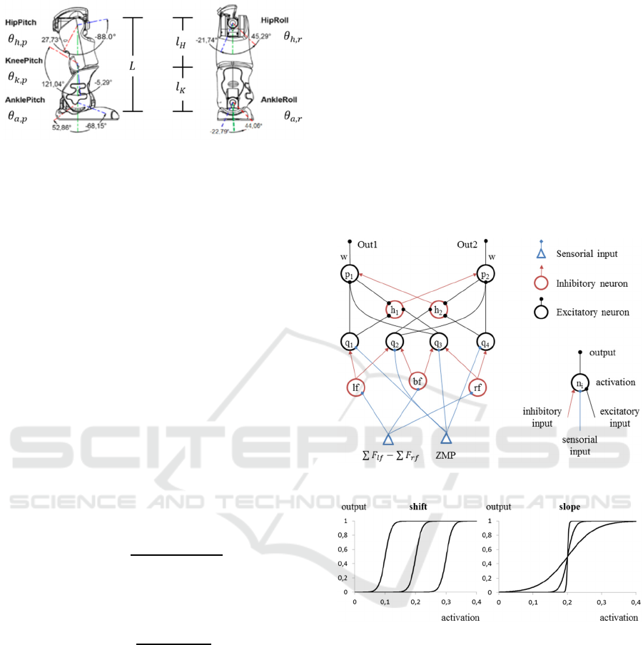
Figure 4: Leg parameters of NAO robot.
it is equal to 0, so that the foot touches the ground.
Simultaneously, the ankle pitch angle
,
of the
moving leg is adjusted by (10) to maintain the
moving foot parallel to the ground.
In (6), the hip pitch angle is adjusted by the torso
pitch angle
,
, defined by (8) as the sum of the hip,
knee and ankle pitch angles of the supporting leg,
because the torso inclination directly affects the hip
pitch angle of the moving leg. The current moving
leg length is determined by (9) based on the current
support leg length and on the desired foot height.
The roll angles are used in the equation to account
for the lateral inclination of both legs.
Free parameter α is used to simplify (6). α
defines the relationship between hip and knee pitch
angles, as shown in (7), and may have different
values in ‘lift’ and ‘extend’, with a higher value in
‘extend’ to produce a more natural motion. The
more negative α is, the straighter the moving leg is
and the larger the step will be (until α is equal to
,
and
,
reaches 0).
,
= −acos
(
,
)
,
(6)
,
=−
,
(7)
,
=
,,
,,
,,
(8)
=
(
.
)∆
(
,
)
(9)
,
=
,
−
,
,
(10)
4 BIOLOGICALLY-INSPIRED
NEURAL NETWORK
4.1 Fundamentals
A general neuron model, represented in the right-
hand side of Fig. 5, may have different types of
inputs, which determine the neuron activation and,
consequently, its output. Whilst inhibitory inputs
have only negative values and excitatory inputs have
only positive values, sensorial inputs can have either
negative or positive values. Activation A
i
of a neuron
i is determined by the weighted sum of its n inputs
Q
j
, as shown in (11). Output O
i
of a neuron i is a
function of its activation A
i
. In this research, a
sigmoid function is adopted as the activation
function, as represented in (12). Parameters s and m
determine the activation function shift and slope,
respectively, and the effects of their modification are
shown in Fig. 6.
=
∑
(11)
=1 1
(12)
Figure 5: Biologically-inspired Neural Network.
Figure 6: Activation functions of neurons.
4.2 Network Structure and Parameter
Determination
The left-hand side of Fig. 5 illustrates the BiNN
structure proposed to stabilize the humanoid robot
walking motion. This research focuses on stabilizing
the humanoid robot from lateral disturbances (y-
direction). Hence, two BiNNs with this structure
would be necessary in order to stabilize the robot in
both x- and y-directions. The sensorial inputs of this
network are: the difference between the sums of all
FSR values of the left foot
∑
and of all FSR
values of the right foot
∑
; and the ZMP,
calculated with the measurements and positions of
Biologically-Inspired Neural Network for Walking Stabilization of Humanoid Robots
99

FSR sensors by the method detailed in (Tamura,
Nozaki and Kawamura, 2015).
The former sensorial input is processed by the
first layer of inhibitory interneurons (lf, bf and rf),
which determine whether each foot is on the ground
or not. Thereby, the slope coefficient modulus of
their activation function (m) is high (500) to
originate a steep threshold function. The slope
coefficient of lf is positive and its shift coefficient is
0.1, causing an input higher than 0.1 to produce an
output, which indicates that the left foot is on the
ground. In contrast, the slope coefficient of rf is
negative and its shift coefficient is -0.1, causing
inputs lower than -0.1 to produce outputs. The
activation function of bf is a combination of the
activation functions of lf and rf, causing values
between -0.1 and 0.1 to produce outputs.
The first layer of excitatory neurons (q
1
, q
2
, q
3
and q
4
) has the ZMP as one of its inputs and
represents the support polygon boundaries in the y-
direction, producing outputs if these boundaries are
violated. Therefore, their shift coefficients exactly
match the values of the boundaries. However, only
the neurons that represent the boundaries of the
current support polygon do not have their outputs
inhibited by the inhibitory interneurons.
Whilst q
1
represents the right boundary of the
support polygon when either only the right foot or
both feet are on the ground, q
2
represents the left
boundary when only the right foot is on the ground,
q
3
represents the right boundary when only the left
foot is on the ground and q
4
represents the left
boundary when either only the left foot or both feet
are on the ground. The slope coefficient modulus of
these neurons is 100 so that outputs are produced
before the ZMP approaches the boundaries, creating
a safety margin.
The second layer of inhibitory interneurons (h
1
and h
2
) also have a steep activation function (m
equal to 500) and a low threshold value (s equal to
0.1). Their purpose is to inhibit the activity of the
opposite p neuron with lateral inhibition dynamics,
which allows only one p neuron to become active at
a time. These neurons receive inputs from p neurons,
generating feedback inhibition, as well as from q
neurons, generating feedforward inhibition. Whilst
feedback inhibition reflects the current state of p
neurons, feedforward inhibition anticipates
variations in their inputs.
The second layer of excitatory neurons (p
1
and
p
2
) produces the neural network outputs (Out1 and
Out2). Their activation functions have a low slope
coefficient (10) and a shift coefficient of 0.5,
providing a varying output in the input range of 0 to
1.0. These neurons receive inputs based on the
distance of the ZMP to the support polygon
boundaries and produce outputs with values from 0
to 1.0, which are transformed into angle increments
by the synaptic weight w.
The synaptic weights of all connections between
neurons are set to 1 in order to simplify the
parameter determination. However, the synaptic
weight w of the outputs (Out1 and Out2) is a free
parameter. w determines the angle increment Δθ
generated by the BiNN, which alters the ankle joint
angles provided by the ‘Walking pattern generation’
block to stabilize the robot motion. Hence, w has a
direct influence on the centre of mass position,
generating a shift in the y-direction Δy
CoM
with Δθ.
From (2), and assuming that the centre of mass
variation in the z-direction is negligible, as in [6],
there are two possibilities to control the ZMP in the
y-direction: by
or by
. But, in the case of
the NAO robot, the maximum value of the second
part of (2) is 0.0014m, due to a low centre of mass
height (0.27m) and a low stall torque (73.44mNm),
which affects the maximum
generated
according to (13). In the equation, m is the robot
mass (5.18kg) and F is the force generated by the
torque T.
=
=
(
)
(13)
In contrast, the maximum value of
is
0.06m, due to an ankle angle limitation (22
o
). The
first part of (2) influences the ZMP position 42 times
more than the second part and, therefore, generating
a Δy
CoM
by choosing the appropriate value of w is
the stabilization method proposed herein.
The ankle angle increment generated by the
BiNN is represented by (14). As the maximum
BiNN output is equal to 1, the maximum ankle
increment is equal to w, as stated in (15). Hence, the
synaptic weight w required to generate a centre of
mass shift Δy
CoM
is determined by (17), which is
derived from (16) and (15).
∆ =
(
1−2
)
(14)
∆
=
(15)
∆
=
(
∆
)
(16)
=asin
∆
(17)
To guarantee the compensation of an external
disturbance with short duration (less than one
second), the centre of mass variation generated by
the ankle motors
must be higher than the
center of mass variation caused by the external force
ICAART 2017 - 9th International Conference on Agents and Artificial Intelligence
100
, as stated in (18). Thereby, a safety factor γ (e.g.
1.1) can be used to transform the inequality into an
equality, as shown in (19). In the equation, the
center of mass velocity caused by the external force
is considered to be equal to the centre of mass
acceleration caused by the external force
multiplied by its duration ∆t. Subsequently, the
center of mass acceleration caused by the external
force is assumed to be equal to the external force
divided by the robot mass.
>
(18)
=
=∆
=
∆
(19)
Assuming the centre of mass variation to be
equal to the centre of mass shift divided by the
iteration step value, as in (20), the synaptic weight w
required to compensate an external force
is
given by (21). This equation allows tuning w
according to the maximum value of the expected
external disturbance. Whilst a higher value of w
compensates higher external forces and causes a
more aggressive behaviour, a lower value of w
causes a smoother behaviour, but cannot compensate
higher external forces.
=
∆
(20)
=asin
∆
(21)
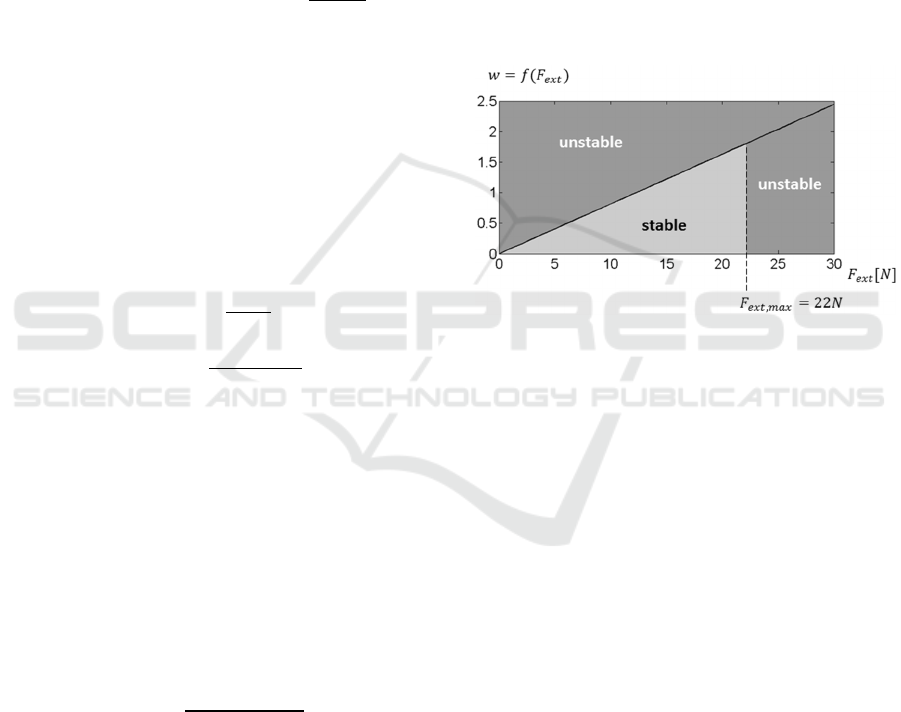
Fig. 7 shows (21) for γ equal to 1.01, ∆t equal to
0.2s,
equal to 0.01s and
equal to 0.27m,
showing the stable and unstable regions that the
equation originates. Force duration of 0.2s was
chosen so that the force acts for a sufficient time so
as not to be considered an impulse. In the figure, the
maximum force that the robot is physically able to
sustain is also shown. This value can be obtained by
substituting the centre of mass acceleration
by
the external force
divided by the robot mass m
in (2), and rearranging the equation as shown in
(22).
=
(
)
(22)
Thereby, substituting the constants m, g and
in the equation and assigning to
the value of
the support polygon boundary (-0.06m) and to
its best feasible position (0.06m), the maximum
external force of 22.48N is obtained. External forces
higher than 22.48N cause a center of mass
acceleration that drives the ZMP out of the support
polygon regardless of the center of mass position
(among its feasible values). In this case, a stepping
approach would be necessary to avoid falling.
5 SIMULATION RESULTS
In this section the BiNN performance for stabilizing
the walking motion of the humanoid robot NAO is
evaluated in two manners. The first regards the
computation time of the BiNN for each iteration
step, whereas the second evaluates the BiNN
capacity of compensating external forces with
different magnitudes and durations. Two software
were used to conduct the simulations: Choregraphe
(v. 2.1.4) and Webots (v. 8.4.0).
Figure 7: Synaptic weight w as a function of the external
force Fext.
5.1 Computation Time
The personal computer used to perform the
simulations has an Intel Core i7-3517U processor
with 1.9GHz and 8GB of random access memory
(RAM). Twenty runs, with 106 iteration steps each,
were conducted to obtain the results. The average
computation time of the BiNN for each iteration step
was 0.0027ms and its coefficient of variation was
0.62%. This computation time corresponds to the
calculation of (11) and (12) for each neuron of the
BiNN.
As an iteration step of 10ms was adopted for
robot control, the BiNN computation time
corresponds to less than 0.1% of the complete
iteration step. Moreover, the low computation time
obtained allows the combination of the BiNN with
other control methods, which have average
computation times of 20ms (Ishihara and Morimoto,
2015), 40ms (Carpentier et al., 2016) and 300ms
(Tedrake et al., 2015) for each iteration step.
Figure 8 illustrates the computation times of
these control methods, showing that the BiNN
computation time is negligible in comparison to
Biologically-Inspired Neural Network for Walking Stabilization of Humanoid Robots
101
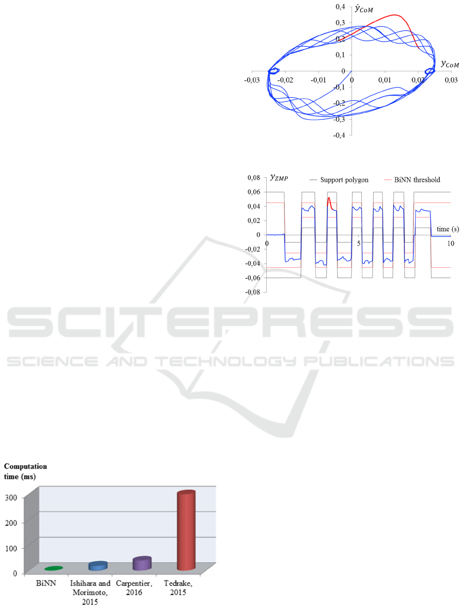
them. This occurs because the BiNN only computes
the current activation and output of its neurons,
whilst predictive approaches are recurrent, i.e., they
compute a sequence of iteration steps in the future in
order to make a decision in the present.
5.2 Walking Stabilization
In order to evaluate the BiNN capacity of
compensating external forces during a walking
motion, the ‘Walking pattern generation’ block and
the BiNN were programmed in Choregraphe
platform. The walking pattern generated had an
average duration of 0.05s for the double standing
phase and of 0.5s for the single standing phase. The
BiNN was evaluated in two simulation studies.
In the first simulation study, a force of 20N in
the y-direction was applied to NAO for 0.2s during
the single standing phase in Webots simulator with a
physics plugin. This force is sufficient to knock the
robot down in the cases in which it is being
controlled either by the default Model Predictive
Control (MPC) method of Choregraphe (Wieber,
2006) or by the open loop version of the control
method proposed (i.e., without the BiNN feedback).
In this simulation, w was set to 1.63, according to
(21). The centre of mass trajectory and the ZMP in
the y-direction, illustrated in Fig. 9 and Fig. 10,
respectively, show that the BiNN was able to
compensate the applied force and that the robot was
able to continue its walking motion. Moreover, the
results also prove that the parameter determination
method proposed is adequate.
Fig. 9 shows the centre of mass position in the y-
direction
as well as its derivative
, whose
combined trajectory present a limit-cycle behaviour.
This trajectory is highlighted in red from the
moment in which the external force was applied.
Figure 8: Computation time comparison.
Figure 9: Centre of mass trajectory.
Figure 10: ZMP as a function of time.
The figure shows that the BiNN stabilizes the robot
when the centre of mass trajectory deviates from its
limit-cycle, bringing the trajectory back to it and
allowing the robot to continue its walking motion
without interruption.
The walking stabilization is also showed in Fig.
10, in which the ZMP, the support polygon
boundaries and the BiNN threshold are plotted as
functions of time. The BiNN threshold represents
the ZMP values from which the q neurons start
generating outputs, which originates a safety margin
that prevents the ZMP from approaching the support
polygon boundaries. In this figure, the ZMP is also
highlighted in red from the moment the external
force was applied. After crossing the BiNN
threshold, the ZMP returned to the stable region in
0.084s, showing a fast response of the BiNN.
The second simulation study regards the
evaluation of the BiNN capacity of compensating
forces with different magnitudes and durations. In
each simulation a force in the y-direction was
applied to NAO in the exact same moment during
the ‘lift’ movement of the single standing phase. The
BiNN performance was compared to the
performance of the default MPC used by
Choregraphe (Wieber, 2006).
ICAART 2017 - 9th International Conference on Agents and Artificial Intelligence
102
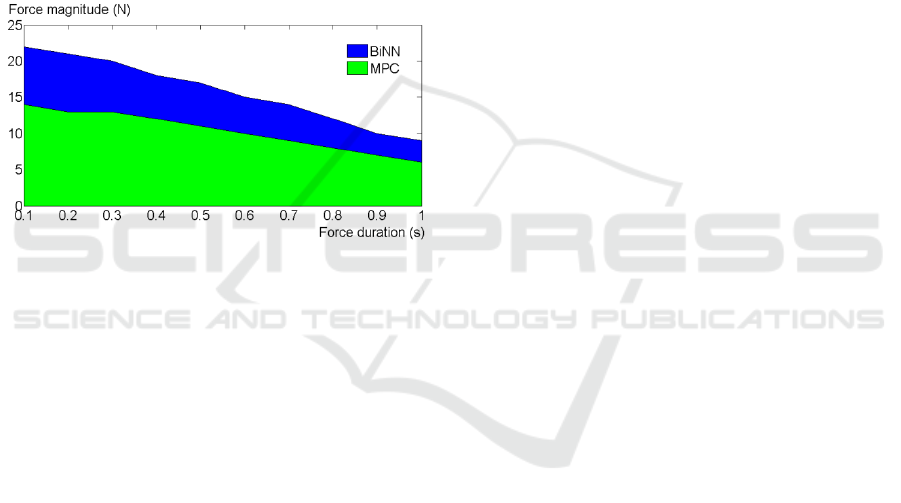
Fig. 11 illustrates the simulation results, showing
that the BiNN was able to compensate a higher force
magnitude for every force duration tested. Each
combination of force magnitude and duration was
evaluated 20 times for each control method. The
lines plotted in the figure correspond to force
magnitudes and durations which the robot was able
to withstand in all 20 simulated experiments.
The BiNN was on average 52.55% better than
the MPC, having higher improvements for shorter
force durations. This occurs due to the BiNN fast
response, which becomes less relevant for longer
force durations. The maximum force compensated
by the BiNN was 22N, applied for 0.1s,
corroborating the theoretical result obtained with
(22) by a margin of 2.14%.
Figure 11: External force compensation.
These results reaffirm that the use of a simpler
stabilization strategy, i.e. to control the ankle joint
with the BiNN, is not only possible due to its low
computation time, but also more effective than the
standard stepping approach of NAO robot. Thereby,
in the cases that the disturbance is moderate (10N-
22N), the ankle joint control proposed would be
active, whereas for stronger disturbances the robot
could use a supplementary stepping approach, such
as those proposed by Stephens and Atkeson (2010)
and Luo et al. (2015).
6 CONCLUSION
This paper presented a Biologically-inspired Neural
Network (BiNN) to stabilize the walking motion of
humanoid robots. The approach proposed considers
scenarios in which foot placement cannot be
changed. Thus, the BiNN uses the Zero Moment
Point (ZMP) as input and alters ankle joint angles to
stabilize the robot.
Simulation studies evaluated the BiNN perfor-
mance in compensating lateral forces with different
magnitudes and durations, which were applied
during the walking motion. The BiNN presented a
fast response to disturbances and had a performance,
on average, 52.55% better than a MPC proposal. The
simplicity and low computation time of the BiNN
(0.0027ms) allows its combination with other
control methods, such as reactive stepping
approaches.
Future research directions encompass using two
BiNNs with the proposed structure to compensate
external forces contained in the x-y plane and three
BiNNs to compensate omnidirectional external
forces. Moreover, experiments will also be planned
in order to evaluate the BiNN performance in
compensating external forces with different
magnitudes and durations applied to the actual NAO
robot.
ACKNOWLEDGEMENTS
This work was supported by CNPq, Conselho
Nacional de Desenvolvimento Científico e
Tecnológico – Brasil / Brazilian National Council of
Scientific and Technological Development.
REFERENCES
Cao, M. and Kawamura, A. (1998). A Design Method of
Neural Oscillatory Networks for Generation of
Humanoid Biped Walking Patterns. In Proceedings of
the International Conference on Robotics and
Automation, pp. 2357-2362.
Carpentier, J., Tonneau, S., Naveau, M., Stasse, O. and
Mansard, N. (2016). A Versatile and Efficient Pattern
Generator for Generalized Legged Locomotion. In
Proceedings of the IEEE International Conference on
Robotics and Automation, pp. 3555–3561.
Endo, G., Morimoto, J., Matsubara, T., Nakanishi, J. and
Cheng, G. (2008). Learning CPG-based Biped Loco-
motion with a Policy Gradient Method: Application to
a Humanoid Robot. International Journal of Robotics
Research, 27(2), pp. 213-228.
Helgadóttir, L. I., Haenicke, J., Landgraf, T., Rojas, R. and
Nawrot, M. P. (2013). Conditioned behavior in a robot
controlled by a spiking neural network. In Proceedings
of the International IEEE/EMBS Conference on
Neural Engineering, pp. 891–894.
Ishihara, K. and Morimoto, J. (2015). Real-time Model
Predictive Control with Two-step Optimization based
on Singularly Perturbed System. In Proceedings of the
IEEE-RAS International Conference. on Humanoid
Robots, pp. 173–180.
Kajita, S., Kanehiro, F., Kaneko, K., Fujiwara, K., Harada,
K., Yokoi, K. and Hirukawa, H. (2003). Biped
Biologically-Inspired Neural Network for Walking Stabilization of Humanoid Robots
103

Walking Pattern Generation by using Preview Control
of Zero-Moment Point. In Proceedings of the IEEE
International Conference on Robotics and
Automation, pp. 1620–1626.
Kandel, E. R., Schwartz, J. H., Jessell, T. M., Siegelbaum,
S. A. and Hudspeth, A. J. (2012). Principles of Neural
Science. McGraw-Hill Education.
Lee, S. H. and Goswami, A. (2012). A momentum-based
balance controller for humanoid robots on non-level
and non-stationary ground. Autonomous Robots, 33(4),
pp. 399–414.
Liu, Z. and Li, C. (2003). Fuzzy neural network quadratic
stabilization output feedback control for biped robots
via H∞ approach. IEEE Transactions on Systems,
Man, and Cybernetics, Part B, 33(1), pp. 67–84.
Lober, R., Padois, V. and Sigaud, O. (2014). Multiple task
optimization using dynamical movement primitives
for whole-body reactive control. In Proceedings of the
IEEE-RAS International Conference. on Humanoid
Robots, pp. 193–198.
Luo, D., Han, X., Ding, Y., Ma, Y., Liu, Z. and Wu, X.
(2015). Learning push recovery for a bipedal
humanoid robot with Dynamical Movement
Primitives. In Proceedings of the IEEE-RAS
International Conference. on Humanoid Robots, pp.
1013–1019.
Maalouf, N., Elhajj, I. H., Asmar, D. and Shammas, E.
(2015). Model-Free Human-Like Humanoid Push
Recovery. In Proceedings of the IEEE International
Conference on Robotics and Biomimetics, pp. 1560–
1565.
Nichols, E., Mcdaid, L. J. and Siddique, N. (2013).
Biologically inspired SNN for robot control. IEEE
Transactions on Cybernetics, 43(1), pp. 115–128.
Rai, J. K., Singh, V. P., Tewari, R. P. and Chandra, D.
(2012). Artificial neural network controllers for biped
robot. In Proceedings of the International Conference
on Power, Control and Embedded Systems, pp. 625-
630.
Sano, A. and Furusho, J. (1990). Realization of natural
dynamic walking using the angular momentum
information. In Proceedings of the IEEE International
Conference on Robotics and Automation, pp. 1476–
1481.
Saputra, A. A., Botzheim, J., Sulistijono, I. A. and Kubota,
N. (2016). Biologically Inspired Control System for 3-
D Locomotion of a Humanoid Biped Robot. IEEE
Transactions on Systems, Man, and Cybernetics:
Systems, 46(7), pp. 898-911.
Stephens, B. J. (2007). Humanoid push recovery. In
Proceedings of the IEEE-RAS International Conferen-
ce. on Humanoid Robots, pp. 589–595.
Stephens, B. J. and Atkeson, C. G. (2010). Push recovery
by stepping for humanoid robots with force controlled
joints. In Proceedings of the IEEE-RAS International
Conference. on Humanoid Robots, pp. 52–59.
Sun, C., He, W., Ge, W. and Chang, C. (2016). Adaptive
Neural Network Control of Biped Robots. IEEE
Transactions on Systems, Man, and Cybernetics:
Systems, PP(99), pp. 1-12.
Taga, G., Yamaguchi, Y. and Shimizu, H. (1991). Self-
organized control of bipedal locomotion by neural
oscillators in unpredictable environment. Biological
Cybernetics, 65(3), pp. 147-159.
Tamura, K., Nozaki, T. and Kawamura, A. (2015). Visual
Servo System for Ball Dribbling by Using Bipedal
Robot Nao. In Proc. Annual Conference of IEEE
Industrial Electronics Society, pp. 3461–3466.
Tedrake, R., Kuindersma, S., Deits, R. and Miura, K.
(2015). A closed-form solution for real-time ZMP gait
generation and feedback stabilization. In IEEE-RAS
International Conference. on Humanoid Robots, pp.
936–940.
Vukobratović, M. and Stepanenko, J. (1972). On the
stability of anthropomorphic systems. Mathematical
Biosciences, 15(1–2), pp. 1–37.
Vukobratović, M., Borovac, B. and Potkonjak, V. (2006).
ZMP: a review of some basic misunderstandings.
International Journal of Humanoid Robotics, 3(2), pp.
153–175.
Wieber, P. B. (2006). Trajectory Free Linear Model
Predictive Control for Stable Walking in the Presence
of Strong Perturbations. In IEEE-RAS International
Conference. on Humanoid Robots, pp. 137 – 142.
Yu, J., Tan, M., Chen, J. and Zhang, J. (2014). A survey
on CPG-inspired control models and system
implementation. IEEE Transactions on Neural
Networks and Learning Systems, 25(3), pp. 441-456.
ICAART 2017 - 9th International Conference on Agents and Artificial Intelligence
104
