
Interactive Appearance Manipulation of Fiber-based Materials
Stefan Krumpen, Michael Weinmann and Reinhard Klein
Institute of Computer Science II, University of Bonn, Bonn, Germany
Keywords:
Reflectance Modeling, Bidirectional Texture Functions, Interactive Rendering.
Abstract:
Achieving a visually appealing experience for the user interaction with photo-realistic digitized micro-fiber
materials is a challenging task. While state-of-the-art high-quality fabric modeling techniques rely on com-
plex micro-geometry representations that are computationally expensive and not well-suited for interactive
rendering, previous interactive reflectance models reach a speed-up at the cost of discarding many of the ef-
fects of light exchange that significantly contribute to the appearance of fabric materials. In this paper, we
present a novel, example-based technique for the interactive manipulation of micro-fiber materials based on
bidirectional texture functions (BTFs) that allow considering fine details in the surface reflectance behavior.
BTFs of the respective material sample are acquired for varying fiber orientations and combined to a single
texture representation that encodes material appearance depending on the view and light conditions as well
as the orientations of the fibers. This model can be efficiently evaluated depending on the user input which,
as demonstrated by our results, allows a realistic simulation of the interaction with micro-fiber materials in
real-time.
1 INTRODUCTION
Due to their wide-spread application for e.g. cloth,
towels or furniture, textiles are among the most im-
portant materials we encounter in our daily life. With
the ongoing trend towards the creation of realistic
content for industrial applications in entertainment or
advertisement, there is also an industrial demand for
accurately capturing the characteristics of textiles as
well as modeling the changes in appearance that are
induced by user-manipulations.
When considering textiles, their structural and op-
tical complexity can be seen in the huge number of
individual variants ranging from micro-fiber materials
to fluffy carpets. It is not only the reflectance behav-
ior of the individual fibers but also the surface struc-
tures at different scales that determine the appearance
of textiles. While larger structures such as the in-
volved yarns influence the appearance characteristics
of fluffy carpets, there is no such yarn level present
for micro-fiber materials and, instead, the orientations
of the small fibers on the surface have a major influ-
ence on the reflectance behavior. Unfortunately, ac-
curately modeling textile materials is challenging as
complex, mesoscopic effects of light exchange such
as the self-masking, self-occlusions, scattering within
the fibers and parallax effects induced by the fibers
occur at the surface. State-of-the-art approaches typ-
ically rely on representing the micro-scale geometry
of fabrics in terms of high-resolution volumes, fiber
curves or procedural, fiber-based models which carry
the burden of high computational demands.
An even more challenging scenario includes the
additional interactive manipulation of digital material
representations. As we all know, moving fingers over
micro-fiber materials induces a change in the structure
of the underlying material, i.e. the small fibers are re-
directed according to the orientation of the movement
while certain constraints such as a possibly dominat-
ing fiber structure due to the manufacturing process
are met. The re-orientation of the fibers, in turn, leads
to a change in appearance when being touched. In this
paper, we aim at reproducing this painting-like inter-
action for digitized materials.
Unfortunately, the computational effort of the
above-mentioned high-quality fabric modeling tech-
niques renders them impractical for an interactive ma-
nipulation in real-time. To overcome this problem, we
present a novel, example-based technique for the in-
teractive manipulation of micro-fiber materials. Our
approach is based on the observations that already
a small number of equilibrium states of fiber ori-
entations are sufficient to describe the complex ap-
pearance of a fiber-based material and that painting-
like interactions with the material change these states.
This, in turn, changes the appearance in the corre-
266
Krumpen S., Weinmann M. and Klein R.
Interactive Appearance Manipulation of Fiber-based Materials.
DOI: 10.5220/0006168902660273
In Proceedings of the 12th International Joint Conference on Computer Vision, Imaging and Computer Graphics Theory and Applications (VISIGRAPP 2017), pages 266-273
ISBN: 978-989-758-224-0
Copyright
c
2017 by SCITEPRESS – Science and Technology Publications, Lda. All rights reserved
sponding area. Furthermore, we argue that direction-
depending reflectance characteristics as given by ori-
ented fibers can be rendered photo-realistically using
bidirectional texture functions (BTFs) (Dana et al.,
1997) that capture mesoscopic effects in their data-
driven representation. Therefore, we represent the ap-
pearance of the individual states of the material us-
ing BTFs but other representations such as spatially
varying bidirectional reflectance distribution func-
tions (SVBRDFs) or anisotropic microflake models
(Jakob et al., 2010) might be used as well. Our
example-based technique allows for the interactive
manipulation of micro-fiber materials by combining
the individual BTFs into a single representation that
can be evaluated in real-time and allows a realistic
simulation of the interaction with micro-fiber materi-
als. In terms of realism, our approach clearly outper-
forms previous approaches for the interactive manip-
ulation of micro-fiber surfaces (Velinov and Hullin,
2016) that rely on SVBRDFs and cannot reproduce
fine details of light exchange induced by the fibers.
2 MICRO-FIBER MATERIALS
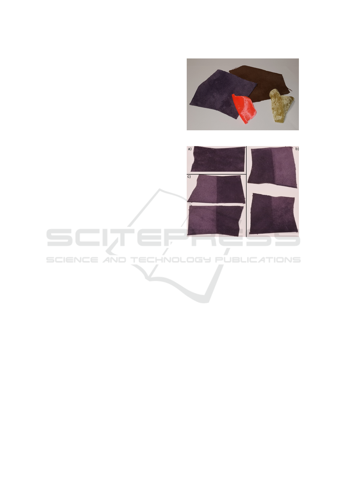
With our approach, we focus on micro-fiber materi-
als such as velvet, plush, flannel, towels, suede and
alcantara. Some examples are shown in Figure 1.
These materials are characterized by loose micro-
scale fibers of different lengths that are not aligned
with the underlying macroscopic surface geometry.
Depending on the manufacturing process, these fibers
might have certain dominant orientations. These ori-
entations can be influenced by external forces such
as tactile user interaction. Pressing and moving e.g.
with a finger over such materials gives the impression
of a painting-like interaction as the fiber orientations
are changed. After leaving a certain region with the
finger, the fibers in this region re-orient to an equilib-
rium state that is responsible for the appearance, i.e.
the reflectance behavior of the material in the corre-
sponding area. Depending on the equilibrium state,
the fibers also might occlude each other, cast shadows
and produce interreflections. This leads to variations
in material appearance depending on the orientations
of the fibers and the respective view-light conditions.
Figure 2a) shows a material with a predominant
fiber orientation in its initial state. In this example,
the dominant fiber orientation is not upright but rather
along a certain direction over the surface. User in-
teraction in terms of sweeping the fingers over the
material into or against the dominant fiber direction
induces different equilibrium states of the fibers that
influence the appearance as can be seen in Figure 2b).
Figure 1: Exemplary samples for micro-fiber materials.
Figure 2: Illustration of the appearance changes due to dif-
ferent fiber orientations: (a) initial state where the fibers
are mainly oriented upright, (b) state where the fibers are
brushed along and against the dominant fiber orientation de-
fined by the material structure, and (c) state where the fibers
are brushed perpendicular to the dominant fiber orientation
and along the opposite direction.
If the manipulation is carried out perpendicular to
the dominant fiber direction, the appearance does not
change if the direction is inverted (see Figure 2c)).
For some materials, additional states have to be taken
into account, e.g. if pressure is applied.
The key observation demonstrated by this exam-
ple is the fact that for a large number of micro-fiber
materials it is sufficient to consider only a finite num-
ber of states. Depending on the material character-
istics, this number might vary but is expected to be
rather small. For example, if the material has no dom-
inant fiber orientation, the consideration of the ini-
tial state where the fibers stand upright and the state
where the fibers are brushed along an arbitrary direc-
tion is sufficient. Capturing the states relevant for a
certain material hence allows the interactive synthesis
of the digitized counterpart of the material.
Interactive Appearance Manipulation of Fiber-based Materials
267

3 RELATED WORK
Our approach represents a connection between the
photo-realistic modeling and rendering of fabrics and
the interactive material synthesis. In the following,
we discuss the most related work in these domains.
Appearance Representation for Textile Materials.
Due to the wide-spread use of fabric materials in
graphics applications in visual prototyping, advertise-
ment or entertainment, the realistic appearance mod-
eling of fabrics has gained attention and intensively
investigated in the literature. We only briefly dis-
cuss the most recent developments and refer to re-
spective surveys (Yuen and W
¨
unsche, 2011; Schr
¨
oder
et al., 2012) for more detailed discussions. While
early investigations focused on BRDF-based micro-
facet models (Ashikmin et al., 2000), recent state-of
the-art techniques rely on the modeling of the micro-
scale geometry of fabrics using volumetric scattering
models (Schr
¨
oder et al., 2011; Jakob et al., 2010;
Zhao et al., 2011) and fiber-based models (Irawan
and Marschner, 2012; Sadeghi et al., 2013; Khun-
gurn et al., 2015; Schr
¨
oder et al., 2015; Zhao et al.,
2016). The latter approaches can be used in com-
bination with BRDF models, models based on bidi-
rectional fiber scattering distribution functions (BFS-
DFs) or models based on bidirectional curve scatter-
ing distribution functions (BCSDFs) for modeling the
reflectance behavior of the individual fibers.
The reason for the success of such micro-scale
models lies in the detailed consideration of individ-
ual characteristics such as fiber orientations and re-
flectance behavior of the individual fibers which al-
lows to accurately represent the light exchange on
fabric surfaces. However, such high-quality fabric
models have high computational demands as well
as high memory requirements and, hence, cannot be
used for real-time rendering but only for static scenes.
In contrast, the interactive simulation of fabrics re-
quires more light-weight reflectance models as e.g.
the adjustment of millions of fibers and the recalcu-
lation of the light exchange are too costly even for
current graphics hardware. With the goal of speed-
ing up the times required for the rendering of fab-
rics, bidirectional texture functions have been synthe-
sized based on known micro-geometry in (Schr
¨
oder
et al., 2013). Since their introduction (Dana et al.,
1997), BTFs have become a popular data-driven re-
flectance model for the photo-realistic depiction of a
huge variety of materials with a surface reflectance
behavior ranging from diffuse to glossy to even local
subsurface scattering characteristics. A BTF repre-
sents the reflectance behavior at the spatial position
x on the object surface depending on the direction
ω
l
of the incoming light and the view direction ω
v
and is therefore defined as a six-dimensional func-
tion ρ
BT F
(x, ω
l
, ω
v
). For detailed surveys on BTFs,
we refer to (Haindl and Filip, 2013; Schwartz et al.,
2014; Weinmann et al., 2016). BTFs are parame-
terized on a flat approximation of the true surface.
This allows capturing mesoscopic effects of light ex-
change such as self-occlusions, self-shadowing or in-
terreflections that occur in surface scratches of fiber-
based materials as well as local subsurface scattering
in the data-driven reflectance representation. While
it is well-known that BTFs can be efficiently com-
pressed (M
¨
uller, 2009) and used for interactive object
visualization (e.g. (Schwartz et al., 2013a)), the edit-
ing of BTFs is difficult. The latter is the the reason
for the development of other approaches that use sim-
pler reflectance models based on SVBRDFs. Most
closely related to the goal of our work is the fitting
of an anisotropic SVBRDF model based on a single-
layer microflake model that can be edited interactively
by manipulating its parameters (Velinov and Hullin,
2016). While this technique aims at a small memory
consumption and high rendering speed, this has been
achieved at the cost of not accurately modeling the
aforementioned mesoscopic effects, that contribute
to the appearance of micro-fiber materials. While
such fine effects of light exchange are captured in
the image-based BTF, including such effects in an
SVBRDF-based representation would require the ex-
plicit modeling of fine surface details in the geometry.
In contrast, our approach is directly based on
BTFs that are acquired using state-of-the-art acquisi-
tion devices and do not require the fitting of a micro-
fiber model. In order to allow an interaction with the
respective material, several BTFs acquired for differ-
ent states of possible fiber orientations are combined
into a single model and, during the interactive syn-
thesis, texture lookups are used to achieve a visually
pleasing impression of the material appearance. As
we use BTFs, we have a higher memory footprint but
still achieve interactive rendering performance while
considering the aforementioned effects. Therefore,
our results yield a better visual experience of the ma-
terial characteristics. To the best of our knowledge,
our approach is the first interactive framework for ma-
nipulating fiber-based materials using BTFs.
Interactions with Texture. Interactions with tex-
ture has become a well-studied topic. The most recent
approaches include the interactive, data-driven high-
fidelity painting system RealBrush (Lu et al., 2013)
and the interactive, example-based texture painting
approach presented in (Luk
´
a
ˇ
c et al., 2015). The lat-
GRAPP 2017 - International Conference on Computer Graphics Theory and Applications
268

ter approach allows to transfer textures with dominant
orientation features onto user-specified, global direc-
tion fields while preserving local texture structures.
While in this work only directional features of 2D tex-
tures are exploited to generate new textures that fol-
low a user-specified direction field, our technique al-
lows to interactively modify the direction field and at
the same time synthesize novel textures from a set of
pre-defined textures that represent different equilib-
rium states. This way, it allows for the manipulation
of complex surface reflectance characteristics.
Time-varying or Interactive Material Synthesis.
Many applications consider time-varying material
appearance. Seminal work focused on modeling
changes in appearance for burning, drying, corrosion
and decaying processes and proposed the first densely
measured database of time and spatially-varying ap-
pearance of flat samples (Gu et al., 2006). Similar
effects were considered in (Sun et al., 2006) with the
drying of different paints or wet surfaces such as ce-
ment, plaster and fabrics, and the accumulation of
dusts on surfaces and the melting of materials such as
chocolate. In both works, flat materials were consid-
ered and analytical BRDFs were fit to acquired mea-
surements performed under varying view-light con-
ditions and at multiple time instances. Furthermore,
time-varying BTFs have been proposed that also con-
sider mesoscopic effects (Langenbucher et al., 2010).
Interactive material design has been studied by
considering manipulations on both small-scale geom-
etry and materials (Wu et al., 2011). However, scat-
tering effects that are important for accurate appear-
ance reproduction at small-scale structures as well
as anisotropic material characteristics are not consid-
ered. More recently, variations in material appearance
induced by interactive user manipulation have been
modeled based on an anisotropic SVBRDF model
(Velinov and Hullin, 2016).
4 METHODOLOGY
In this section, we first provide an overview of the
proposed technique and subsequently discuss the re-
spective key components in more detail.
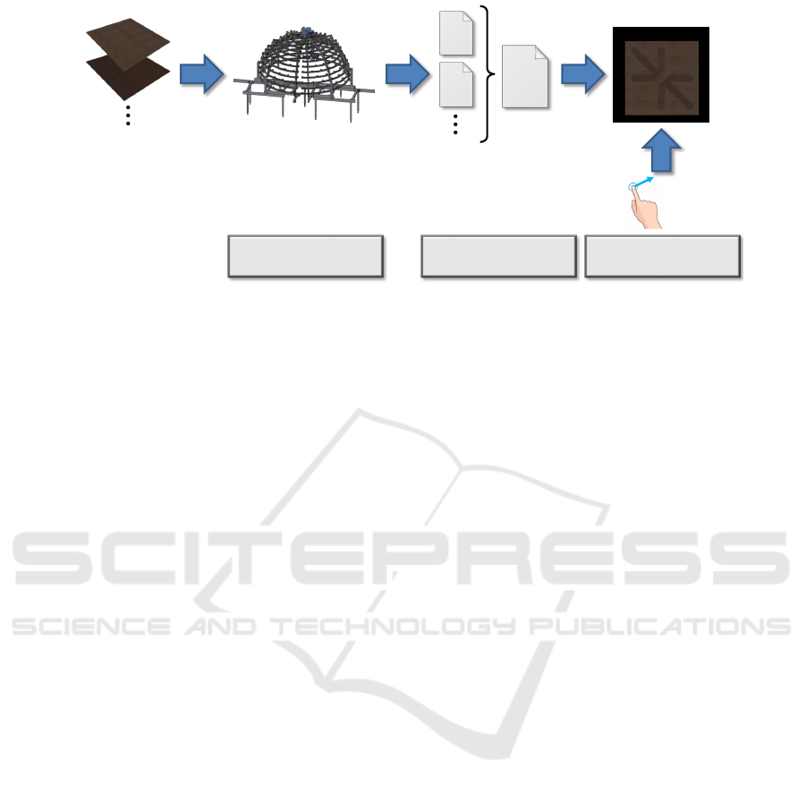
The main components of our techniques are il-
lustrated in Figure 3. In a pre-processing stage, we
acquire micro-fiber materials in different states such
as different fiber orientations (see Section 2) using
a state-of-the-art reflectance acquisition device. This
results in the computation of one BTF for each equi-
librium state of the fibers. The resulting BTFs are
then combined into a single texture array that holds
the information regarding the appearance of a respec-
tive material under different view-light configurations
and different orientations of the fibers. In the final on-
line stage, an interactive appearance simulation takes
the per-material texture array to specify an initial con-
figuration of view and light conditions as well as the
fiber directions and allows the user to virtually brush
the material with his/her fingers and change the view
and light conditions, while the appearance changes
accordingly.
4.1 Reflectance Representation and
Acquisition
As the reproduction of fine details in the reflectance
behavior induced by the individual fibers is of utmost
importance for a visually appealing impression of the
material, we focus on the use of BTFs for modeling
the reflectance behavior of micro-fiber materials. In
particular, we measure an individual material sample
several times for different fiber states τ with a stan-
dard acquisition device (Schwartz et al., 2013b). A
material sample with a certain fiber state τ is placed
onto a turntable and observed by eleven cameras that
are mounted on an arc with increments of 7.5
◦
and
have a resolution of 2,048 × 2,048 pixels. After an
initial structured light based acquisition of the approx-
imate surface, the 198 LED light sources mounted on
the upper hemisphere are used to sequentially illumi-
nate the material sample from different light source
positions while the material sample is captured by
the cameras under different turntable rotations. Af-
ter the acquisition, we project the captured HDR im-
ages onto the surface which is followed by a resam-
pling of the data into local coordinate systems at each
surface point and a final Decorrelated Full-Matrix-
Factorization (DFMF) compression. During the com-
pression, an SVD is computed for each color channel
after a conversion into the YUV color space, which
results in Eigen-ABRDFs and Eigen-Textures. From
these, the most informative ones are kept to achieve
the compression. Finally, this results in an individual
BTF for each of the fiber states. In order to obtain a
single reflectance representation that also encodes the
changes in reflectance behavior induced by the fiber
characteristics in addition to the view and light di-
rections, these BTFs ρ
BT F
τ
(x, ω
l
, ω
v
) are merged into
a single BTF ρ
BT F
(x, ω
l
, ω
v
, τ) that additionally in-
cludes the dependency on the fiber state τ.
4.2 Interactive Simulation
The data-driven representation resulting from the pre-
vious step models material appearance depending on
Interactive Appearance Manipulation of Fiber-based Materials
269
merged
BTF
BTF 1
BTF 2
Appearance Acquisition
Samples with varying
fiber orientations
Appearance Modeling
User Input
Interactive Simulation
Figure 3: Overview of the main components of the proposed technique: In an initial step, micro-fiber materials with different
fiber orientations are acquired with a reflectance acquisition device which results in one BTF per fiber orientation of the
material. The individual BTFs are combined into a single texture array that contains the reflectance characteristics of the
material under varying view and light conditions as well as varying fiber orientations. Based on this representation and an
input by the user, an interactive simulation of the reflectance behavior for manipulated fiber orientations is achieved.
the spatial position on the micro-fiber surface, the
view direction, the light direction and the state τ of the
fibers. Before we describe how an efficient rendering
can be performed despite the rather high dimensional-
ity of the measure data, we first discuss the realization
of user interactions with micro-fiber materials.
User Interaction. To achieve an appealing experi-
ence for the painting-like interaction of the user with
the material, we aim at an as-intuitive-as-possible in-
terface that allows the user to brush over the digi-
tized micro-fiber material. In more detail, the mate-
rial is shown to the user who can change the view-
ing and lighting conditions and is allowed to directly
paint on the object via the mouse. The latter is imple-
mented by projecting the mouse position into the uv-
parametrization of the object and using the resulting
coordinates to draw in a direction texture. This tex-
ture has three color channels that hold the direction of
the stroke (d
x
, d
y
) in uv-space in the red and green
color channels, and a brush-strength s in the blue-
channel, where s = 1 means that the material is com-
pletely brushed and s = 0 means that the correspond-
ing equilibrium state remains unchanged. To take into
account that a hard transition between brushed and
unbrushed fibers at the edges of a stroke is unrealistic
for the simulated materials, we interpolate s between
0 and 1 at the edges of the stroke. By interpolating
the corresponding BTFs of the borders of the brush-
stroke according to s, we approximate the reflectance
behavior at these parts. Please note, that a more ac-
curate interpolation might be achieved based on more
sophisticated techniques (Bonneel et al., 2011), how-
ever, simple linear interpolation allows for faster ren-
dering. While drawing, we brush all fibers below the
virtual ”‘finger”’ in the direction of the movement of
the finger independent of their position relative to the
brush center, but according to the resulting equilib-
rium state. This state is chosen depending on the an-
gle between the movement direction of the finger in
texture space and the dominant fiber direction stored
with each material. At each frame, only the parts of
the direction texture which were changed during the
frame are updated in the video memory.
Rendering. Based on the aforementioned direction
texture generated by the user interactions, the re-
flectance model from Section 4.1 has to be efficiently
evaluated on the GPU. For this purpose, the measured
BTFs, consisting of the Eigen-Textures and Eigen-
ABRDFs for the three color-channels, and the direc-
tion texture containing the user generated direction
field and brush-strength information are passed to the
fragment shader. The shader samples the direction-
texture to determine which state of the material has
to be applied for the current fragment, and how the
corresponding BTF has to be rotated in order to align
its orientation according to the user-defined direction
texture. Note, that the BTFs are oriented in such a
way that the positive u-axis of the corresponding 2D
texture is aligned with its dominant fiber direction. If
the brush strength is s = 0, the shader only evaluates
the BTF representing the material in its initial state.
For s = 1, the BTF for the state τ corresponding to the
direction of the brush stroke is evaluated. If 0 < s < 1,
which occurs on the edges of a brush stroke, the BTFs
acquired for the initial state and the state with the ad-
equate fiber orientations are evaluated and the results
are interpolated. The material state which needs to be
sampled is determined from the angle α between the
GRAPP 2017 - International Conference on Computer Graphics Theory and Applications
270

vector (1, 0) in uv-space and the direction d = (d
x
, d
y
)
of the brush stroke. Since only a few fiber orienta-
tions for a few angles were measured, we select the
one which is closest to the angle α of the brush stroke.
The directions ω
l
and ω
v
used to sample the BTF are
defined w.r.t. the local coordinate system at x. For
sampling the material brushed into a certain direction
d at a texel x, we rotate the tangent t defining the
local coordinate system by −α = −atan(
d
y
d
x
) around
the normal n, and the texture-coordinate by α around
the center of the texture. The rotated coordinate sys-
tem and texture-coordinate are then used to sample
the BTF of the brushed material.
5 RESULTS
We evaluate our technique with respect to its capabil-
ity to accurately reproduce the characteristic material
appearance during user interaction and its rendering
performance.
5.1 Visual Quality
To evaluate the proposed method regarding the
achieved visual quality, we measured BTFs of a fiber
based material sample in two different states: One
state where all fibers of the material are arranged
upwards, and a second state where all fibers were
brushed into one direction. As the used material does
not have a predominant direction, it is sufficient to
capture only one direction of the fibers, as the ap-
pearance is invariant to the direction of interaction.
Figure 4 shows original images of the material sam-
ple, lit from different directions, were the fibers in
the middle were brushed from right to left. It is
clearly visible that the individual parts have a dif-
ferent reflectance behavior when the light direction
changes. Figure 5 shows how the material rendered
using our method behaves when the light or view di-
rection is changed. Mesoscopic effects of light ex-
change such as interreflections, self-shadowing and
self-occlusions are preserved in the synthesized mate-
rial as well as parallax effects. As the used BTFs are
not tileable, there are discontinuities in the textures.
Figure 6 shows a comparison to a previous technique
(Velinov and Hullin, 2016). Furthermore, Figure 7
shows a rendering of the material applied to a curved
object using an environment map.
5.2 Rendering Performance
All of our renderings were performed on a machine
with a NVidia Geforce 980 GTX with 4GB of VRAM.
The most costly part of our shader is the evaluation
of the BTFs, as this comes with a high amount of
texture lookups per fragment, especially when both
BTFs have to be evaluated on the edges of a brush-
stroke. The visual quality of BTFs greatly depends
on the number of BTF components used for ren-
dering. In our evaluations, we obtained the insight
that using 50 Eigen-Textures and Eigen-ABRDFs for
the brightness-channel and eight Eigen-Textures and
Eigen-ABRDFs for the color channels is sufficient for
a good visual quality, while allowing for high framer-
ates. For rendering without user manipulations, we
achieved framerates of 125 frames per second in av-
erage with the BTF settings mentioned above for the
scene in the bottom row of Figure 5. During user
interaction, where parts of the direction texture are
changed and uploaded to the GPU, which is a rather
slow operation, the framerate drops down to 80 FPS.
The used BTFs have a resolution of 900 × 400 pixels,
and about 50 MB of video memory each for the used
settings.
6 CONCLUSION
In this paper, we proposed a data-driven method to
interactively manipulate fiber-based materials. As
demonstrated in our experiments, our technique is
capable of reproducing several effects such as self-
occlusions, self-shadowing or the scattering between
the fibers during the interactive simulation and,
hence, clearly outperforms the previous state-of-the-
art (Velinov and Hullin, 2016) that cannot reproduce
such effects reliably in terms of realism. To overcome
the limited size of the measured BTFs, one could ap-
ply the concept of video-textures (Sch
¨
odl et al., 2000)
to hide the tiling-artifacts. This could be achieved by
searching for patches inside the BTF for the current
material state that are similar to the one currently un-
der the brush, instead of moving over the border of
the BTF texture. Our framework relies on the avail-
ability of BTFs measured for different material states.
For certain materials and scenarios, such as brushing
fiber-based materials, where only a few states have to
be considered, this simple approach is is highly ef-
ficient. To include further interactions such as com-
pacting the fibers, additional states of the considered
material have to be measured. This means that the
total acquisition effort might become impractical if
many states have to be considered. However, as at
Interactive Appearance Manipulation of Fiber-based Materials
271
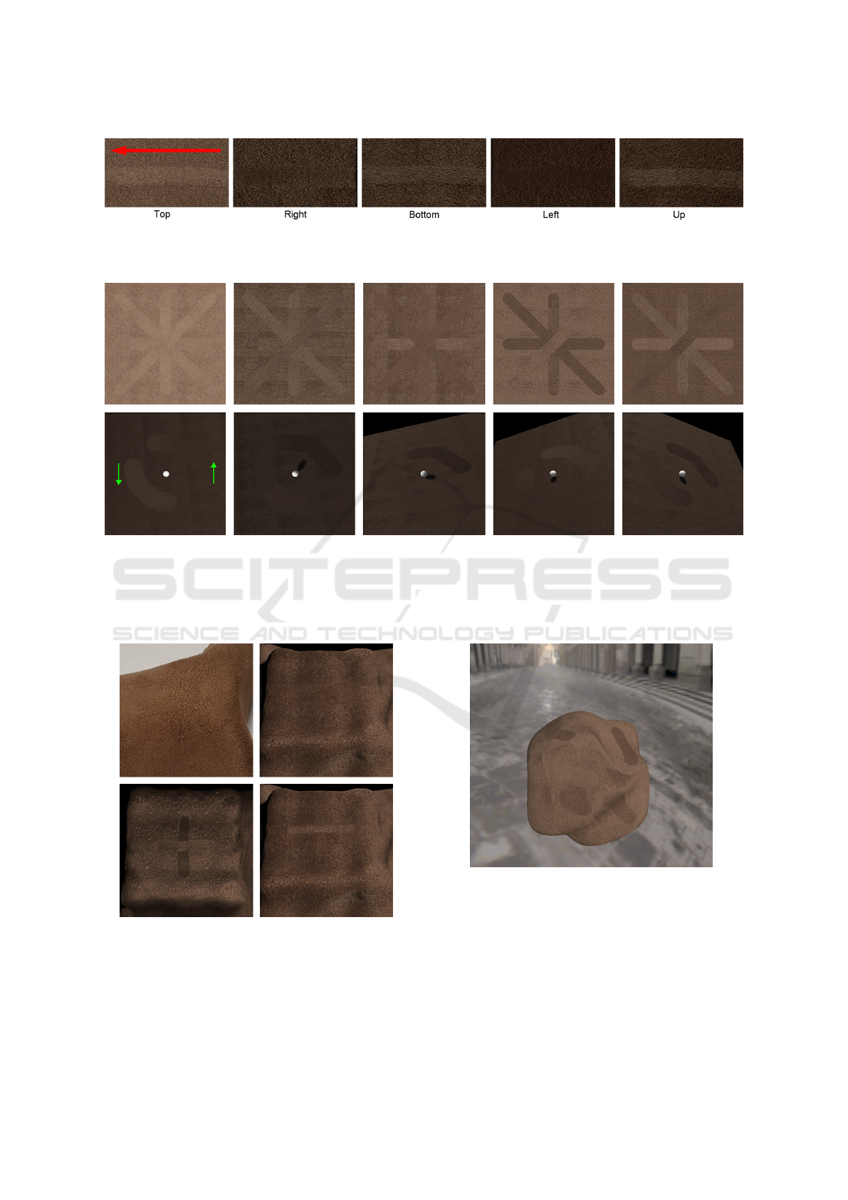
Figure 4: The material sample used for our experiments under different lighting conditions where parts of the sample were
brushed into the direction indicated by the red arrow using a finger. Note that the fibers in the unbrushed parts are not arranged
straight upwards, which is why there is a larger change in brightness also in these parts.
Figure 5: Renderings of the captured material using our technique: When brushing the fibers into different directions (top
row), the characteristic differences in appearance induced by the fiber orientations are clearly visible as the light direction
changes. Furthermore, renderings of two finger-strokes obtained using our technique are shown (bottom row). The arrows
in the bottom-left image indicate the directions in which the virtual finger was moved. The white sphere is included to
better visualize the light direction. The fibers in the brushed areas behave differently depending on their orientation and the
view-light conditions. This figure is best viewed in color and by using the zoom function.
Figure 6: Comparison between the real material (upper
left), our measured BTF (upper right) and renderings of
the manipulated material obtained using a state-of-the-art
technique (Velinov and Hullin, 2016) (bottom left) and our
technique (bottom right). Please note that the lighting con-
ditions are different in the photo and the renderings.
Figure 7: Rendering of the material with several brush-
strokes under environment-lighting. The environment is ap-
proximated by eight directional lights.
most two BTFs have to be evaluated for a single frag-
ment, the efficiency of the rendering pipeline remains
unchanged but the memory consumption increases.
Furthermore, a more general editing of the materi-
als such as changing its colors is not possible. Such
a material editing might be implemented by fitting
GRAPP 2017 - International Conference on Computer Graphics Theory and Applications
272

SVBRDFs to the BTF data, storing the residual of the
Y channel in a BTF and adding the residual again dur-
ing the rendering process.
REFERENCES
Ashikmin, M., Premo
ˇ
ze, S., and Shirley, P. (2000). A
microfacet-based BRDF generator. In Proceedings of
the 27th Annual Conference on Computer Graphics
and Interactive Techniques, pages 65–74.
Bonneel, N., van de Panne, M., Paris, S., and Heidrich, W.
(2011). Displacement interpolation using lagrangian
mass transport. ACM Trans. Graph., 30(6):158:1–
158:12.
Dana, K. J., Nayar, S. K., van Ginneken, B., and Koen-
derink, J. J. (1997). Reflectance and texture of real-
world surfaces. In Proceedings of the IEEE Con-
ference on Computer Vision and Pattern Recognition
(CVPR), pages 151–157.
Gu, J., Tu, C.-I., Ramamoorthi, R., Belhumeur, P., Matusik,
W., and Nayar, S. (2006). Time-varying surface ap-
pearance: Acquisition, modeling and rendering. ACM
Trans. Graph., 25(3):762–771.
Haindl, M. and Filip, J. (2013). Visual Texture: Accu-
rate Material Appearance Measurement, Representa-
tion and Modeling. Advances in Computer Vision
and Pattern Recognition. Springer-Verlag New York
Incorporated.
Irawan, P. and Marschner, S. (2012). Specular reflection
from woven cloth. ACM Trans. Graph., 31(1):11:1–
11:20.
Jakob, W., Arbree, A., Moon, J. T., Bala, K., and
Marschner, S. (2010). A radiative transfer frame-
work for rendering materials with anisotropic struc-
ture. ACM Trans. Graph., 29(4):53:1–53:13.
Khungurn, P., Schroeder, D., Zhao, S., Bala, K., and
Marschner, S. (2015). Matching real fabrics with
micro-appearance models. ACM Trans. Graph.,
35(1):1:1–1:26.
Langenbucher, T., Merzbach, S., M
¨
oller, D., Ochmann, S.,
Vock, R., Warnecke, W., and Zschippig, M. (2010).
Time-varying BTFs. In Central European Seminar on
Computer Graphics for Students (CESCG).
Lu, J., Barnes, C., DiVerdi, S., and Finkelstein, A. (2013).
Realbrush: Painting with examples of physical media.
ACM Trans. Graph., 32(4):117:1–117:12.
Luk
´
a
ˇ
c, M., Fi
ˇ
ser, J., Asente, P., Lu, J., Shechtman, E., and
S
´
ykora, D. (2015). Brushables: Example-based edge-
aware directional texture painting. Comput. Graph.
Forum, 34(7):257–267.
M
¨
uller, G. (2009). Data-Driven Methods for Compression
and Editing of Spatially Varying Appearance. Disser-
tation, Universit
¨
at Bonn.
Sadeghi, I., Bisker, O., De Deken, J., and Jensen, H. W.
(2013). A practical microcylinder appearance model
for cloth rendering. ACM Trans. Graph., 32(2):14:1–
14:12.
Sch
¨
odl, A., Szeliski, R., Salesin, D. H., and Essa, I. (2000).
Video textures. In Proceedings of the Annual Con-
ference on Computer Graphics and Interactive Tech-
niques, SIGGRAPH ’00, pages 489–498.
Schr
¨
oder, K., Klein, R., and Zinke, A. (2011). A volumetric
approach to predictive rendering of fabrics. In Pro-
ceedings of the Eurographics Conference on Render-
ing (EGSR), pages 1277–1286.
Schr
¨
oder, K., Klein, R., and Zinke, A. (2013). Non-
local image reconstruction for efficient computation
of synthetic bidirectional texture functions. Computer
Graphics Forum, 32:61–71.
Schr
¨
oder, K., Zhao, S., and Zinke, A. (2012). Recent ad-
vances in physically-based appearance modeling of
cloth. In SIGGRAPH Asia 2012 Courses, pages 12:1–
12:52.
Schr
¨
oder, K., Zinke, A., and Klein, R. (2015). Image-based
reverse engineering and visual prototyping of woven
cloth. IEEE Transactions on Visualization and Com-
puter Graphics, 21(2):188–200.
Schwartz, C., Ruiters, R., Weinmann, M., and Klein, R.
(2013a). Webgl-based streaming and presentation of
objects with bidirectional texture functions. J. Com-
put. Cult. Herit., 6(3):11:1–11:21.
Schwartz, C., Sarlette, R., Weinmann, M., and Klein, R.
(2013b). DOME II: A parallelized BTF acquisition
system. In Proceedings of the Eurographics Workshop
on Material Appearance Modeling, pages 25–31.
Schwartz, C., Sarlette, R., Weinmann, M., Rump, M., and
Klein, R. (2014). Design and implementation of prac-
tical bidirectional texture function measurement de-
vices focusing on the developments at the University
of Bonn. Sensors, 14(5):7753–7819.
Sun, B., Sunkavalli, K., Ramamoorthi, R., Belhumeur, P.,
and Nayar, S. (2006). Time-varying BRDFs. In Pro-
ceedings of the Second Eurographics Conference on
Natural Phenomena (NPH), pages 15–23.
Velinov, Z. and Hullin, M. B. (2016). An Interactive Ap-
pearance Model for Microscopic Fiber Surfaces. In
Hullin, M., Stamminger, M., and Weinkauf, T., edi-
tors, Vision, Modeling and Visualization.
Weinmann, M., Langguth, F., Goesele, M., and Klein, R.
(2016). Advances in geometry and reflectance acqui-
sition. In Eurographics 2016 Tutorials.
Wu, H., Dorsey, J., and Rushmeier, H. (2011). Physically-
based interactive bi-scale material design. In Proceed-
ings of the 2011 SIGGRAPH Asia Conference, pages
145:1–145:10.
Yuen, W. and W
¨
unsche, B. C. (2011). An evaluation on
woven cloth rendering techniques. In Proceedings of
the International Image and Vision Computing New
Zealand Conference (IVCNZ 2011), pages 7–12.
Zhao, S., Jakob, W., Marschner, S., and Bala, K. (2011).
Building volumetric appearance models of fabric
using micro CT imaging. ACM Trans. Graph.,
30(4):44:1–44:10.
Zhao, S., Luan, F., and Bala, K. (2016). Fitting procedural
yarn models for realistic cloth rendering. ACM Trans.
Graph., 35(4):51:1–51:11.
Interactive Appearance Manipulation of Fiber-based Materials
273
