DM-UAV: Dexterous Manipulation Unmanned Aerial Vehicle
Alberto Torres
1
, Francisco Candelas
2
, Damian Mira
1
and Fernando Torres
2
1
Computer Science Research Institute, University of Alicante, Alicante, Spain
2
Physics, Systems Engineering and Signal Theory Department, University of Alicante, Alicante, Spain
Keywords: Dexterous Robotic Manipulation, Aerial Grasping, UAV.
Abstract: This paper describes a novel aerial manipulation system, a DM-UAV which is composed of a drone with a
robotic hand. The main objective is to grasp a target object with the robotic hand. We assume that the object
position is known so the drone flies to this position and lands, then the robotic hand can grasp the target
object. After of that, the drone can take off in order to transport the object to other location. This system can
be very useful for different field applications, f.e. agriculture, to clean the trash on the field, to eliminate
contaminating objects, etc.
1 INTRODUCTION
The aerial manipulation traditionally has been
focused in drones with a simple gripper in the end of
a 2-DOF manipulator. Most of the time this system
is used to grasp cylinder objects or to hang the
drone. In (Courtney, 2011; Thomas, 2013), an avian-
inspired robotic system is presented in order to perch
or to grasp a cylinder.
We don’t know any experience with a robotic
hand in a drone. In contrast with other robotic tools,
a robotic hand has the main advantage of providing
much more DOF, which enables it to make more
complex manipulation tasks, such as catching
complex shapes, grasping from different
orientations, etc.
For more complex manipulation tasks,
manipulators with more DOF’s are used linked to a
drone (Korpela, 2012; Orsag, 2012).
In some cases, a vision system is used to detect
cylindrical structures in order to hang the drone
(Thomas, 2016).
The system proposed in this paper is more
complex: in the future, we plan to have a vision
system in the drone for detecting a target object in
order to grasp it with a complex robotic hand. Now,
in this paper we assume that the object position is
known.
The remainder of the paper is organized as
follows. The next section describes the design of the
system, and explains each individual part in detail.
Section 3 describes the grasp planner proposed. This
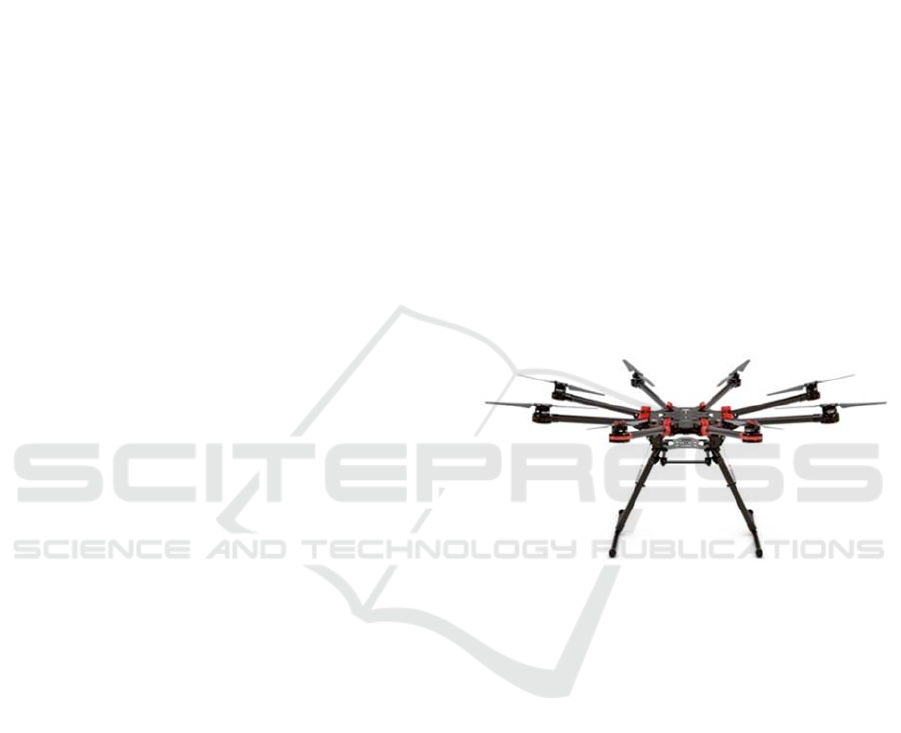
Figure 1: DJI Spreading Wings S1000+ drone.
planner has been tested for the authors in others
complex tasks too. Section 4 contains the results and
the future works. Finally, the last section is
dedicated to the conclusions.
2 SYSTEM DESIGN
This section describes the robot, including the
physical platform and the hardware architecture. The
robot is based on a Spreading Wings S1000+ drone,
and an Allegro hand.
2.1 The Spreading Wings S1000+
Drone
The Spreading Wings S1000+ (DJI, Shenzhen,
China), which is shown in Figure 1, has a total
weight without charge of 4.2 kg, but it is able to fly
with a total weight of 11 kg. Thus, there are 6.8 kg
Torres A., Candelas F., Mira D. and Torres F.
DM-UAV: Dexterous Manipulation Unmanned Aerial Vehicle.
DOI: 10.5220/0006186701530158
In Proceedings of the 9th International Conference on Agents and Artificial Intelligence (ICAART 2017), pages 153-158
ISBN: 978-989-758-219-6
Copyright
c
2017 by SCITEPRESS – Science and Technology Publications, Lda. All rights reserved
153
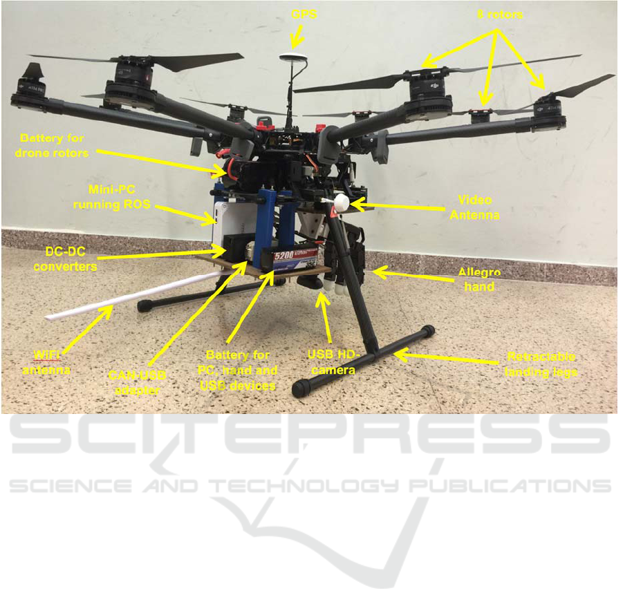
Figure 2: Main additional equipment added to the drone.
free for the Allegro hand, the rest of the necessary
equipment, and the target object. Figure 2 details the
additional equipment included in the drone in order
to command the robotic hand, apart from its own
hand.
Among this equipment, a mini-PC (MSI Cubi-
007XEU with Intel Pentium 380SU 1,9GHz) works
as the hand controller, and, for that, it executes ROS
Indigo on Ubuntu 14.04 LTS. As the Allegro hand
has a CAN serial interface, a CAN-USB adapter
(Peak PCAN-USB) is required to connect the mini-
PC to the hand. Also, the tactile sensors of the hand
are connected to the mini-PC, in this case directly by
USB. Moreover, the mini-PC communicates with a
ground station through a wireless link. Currently this
radio link is based on a WiFi WLAN, which is
enough for a first prototype and testing, although we
are working on replacing it by a dedicated long
distance radio-link. Thus, the system includes a high
power WiFi-USB interface with a high-gain antenna
(Approx APPUSB150H3).
The system also has two cameras as follows: a
frontal camera used mainly for manual piloting, and
an USB HD-camera oriented vertically to the
ground. The field of view of the last camera includes
also the workspace of the hand. These cameras
presently is used only for manual piloting, in the
future will be used not only for recognition of
structures on the ground, but also for grasping tasks.
In addition to the original GNSS receiver of the
drone, we have connected other low-cost high-
precision GNSS with compass (Ublox M8N) to the
mini-PC by means of a serial-USB converter. This is
necessary, because the closed architecture of the
drone makes very difficult to access to flight data
from its original hardware. Finally, the equipment
also includes a dedicated battery and two DC-DC
converters to power the hand, the PC and the USB
devices.
As commented before, the original hardware of the
drone has a closed architecture, and, thus, it is
difficult to access to data from the flight controller
or to send commands directly to it. Thus, in order to
get the automatic flight of the drone, we use
currently a ground station which receives real-time
information from the drone such as flying and
positioning data, and commands the drone by means
of a RC (remote controller) according to the
received information and previously-planned general
paths. More specifically, the ground station is a PC
which is communicated with, on the one hand, the
computer aboard the drone thought the wireless link
ICAART 2017 - 9th International Conference on Agents and Artificial Intelligence
154
described previously, and, on the other hand, the
training port available on a 14SG RC from Futaba
which enables the PC to manage all the drone
controls. The connection with RC is not direct, and it
is based on an Arduino board which works as a
bridge translating commands from USB to PWM
signals required by the training port of the RC. The
ground station also provides real-time information to
the human operator about the trajectories and tasks
that the drone is performing, while allows operator
to define paths and tasks, or even take the control of
the drone for a manual piloting.
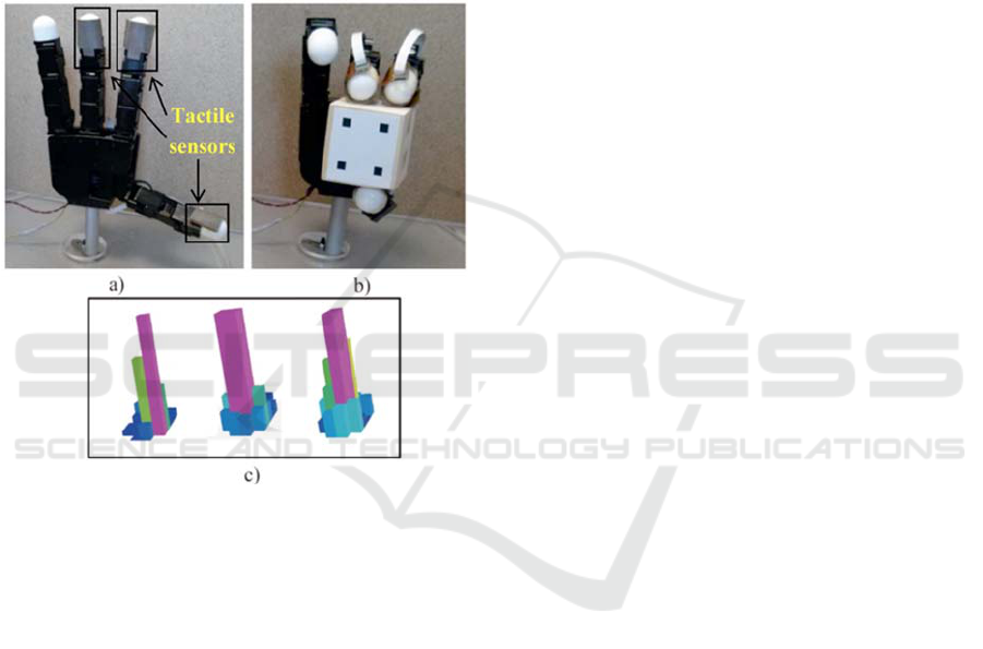
Figure 3: (a) Allegro hand with the tactile sensors installed
in the fingertips’ surface. (b) Allegro hand grasping the
object to be manipulated. (c) Different 3D representation
of the pressure measurements registered by the arrays of
tactile sensors.
2.2 The Allegro Robotic Hand
The robotic manipulation system is based on the
Allegro robotic hand (Wonik Robotics Seoul, Korea)
(see Figure 3). This hand has four fingers and
sixteen independent torque-controlled joints (four
dof per each finger). This robotic hand has a
lightweight and portable anthropomorphic design
very suitable for low-cost dexterous manipulation in
research. The hand weight is 1.09 kg. It is capable of
holding up to 5 kg and it has support for real-time
control and online simulation. In addition, a set of
tactile sensors is employed as additional tool in the
manipulation system (see Figure 3a). These sensors
are installed in an extrinsic configuration (Tegin,
2005) on the Allegro hand. The sensors are located
at the three hand fingertips that will be used during
the manipulation (furthermore, only the three last
degrees of freedom of each finger will be controlled,
resulting in a non-redundant system). The tactile
sensors are pressure sensing arrays, type PPS
RoboTouch (Pressure Profile Systems, Inc., Los
Angeles, CA, USA), which can register pressure
values in the range 0–140 kPa with a frequency of
30 Hz and a sensitivity of 0.7 kPa. Figure 3c shows a
3D representation of the pressure measurements
registered by these sensors during a manipulation
task. The force exerted by the fingertip is computed
using the pressure measurements of the tactile
sensors. These measurements are multiplied by the
area of each sensor, 25 mm
2
, so the forces are
obtained. The mean of these forces is considered as
the force applied by the fingertip. Moreover, the
contact points are supposed to be in the sensor of
maximum pressure exerted.
3 GRASP PLANNER
This section presents the general structure of the
manipulation planner. This manipulation planner
uses the geometric model of the object and the
fingers in order to determinate the contacts between
the fingers of the robotic hand and the manipulated
object.
3.1 Kinematics Formulation
We consider the robotic hand as a set of k fingers
with three degrees of freedom. Each finger holds an
object considering contact points with friction and
without slippage. In order to firmly grasp and
manipulate the object, the grasp is considered to be
an active form closure. Thus, each fingertip i is
exerting a fingertip force f
Ci
∈ 3 within the friction
cone at the contact point. The grasping constrain
between the robot and the object is done by the
grasp matrix J
G
=[J
T
G1
…J
T
Gk
]
T
∈R
3k×6
(Murray, 1994)
which relates the contact forces f
C
= [f
Cl
T
… f
Ck
T
]
T
at the fingertips to the resultant force and moment τ
o
∈
6
on the object:
τ
o
=J
G
⋅f
C
(1)
where f
C
and τ
o
are both expressed in the object
coordinate frame S
0
fixed to the object mass center.
This equation derives the kinematics relation
between velocity of the object ẋ
o
∈
6
and velocity
of the contact point v
Ci
∈
6
:
v
Ci
=J
Gi
⋅ ẋ
o
(2)
DM-UAV: Dexterous Manipulation Unmanned Aerial Vehicle
155
where x
o
denotes the position and orientation of the
object in the contact point from S
0
. Extending
Equation (2) for all the contact points and
considering the object velocity with respect the
camera coordinate frame, the resulting expression is:
v
C
=J
GC
⋅ ẋ
C
o
(3)
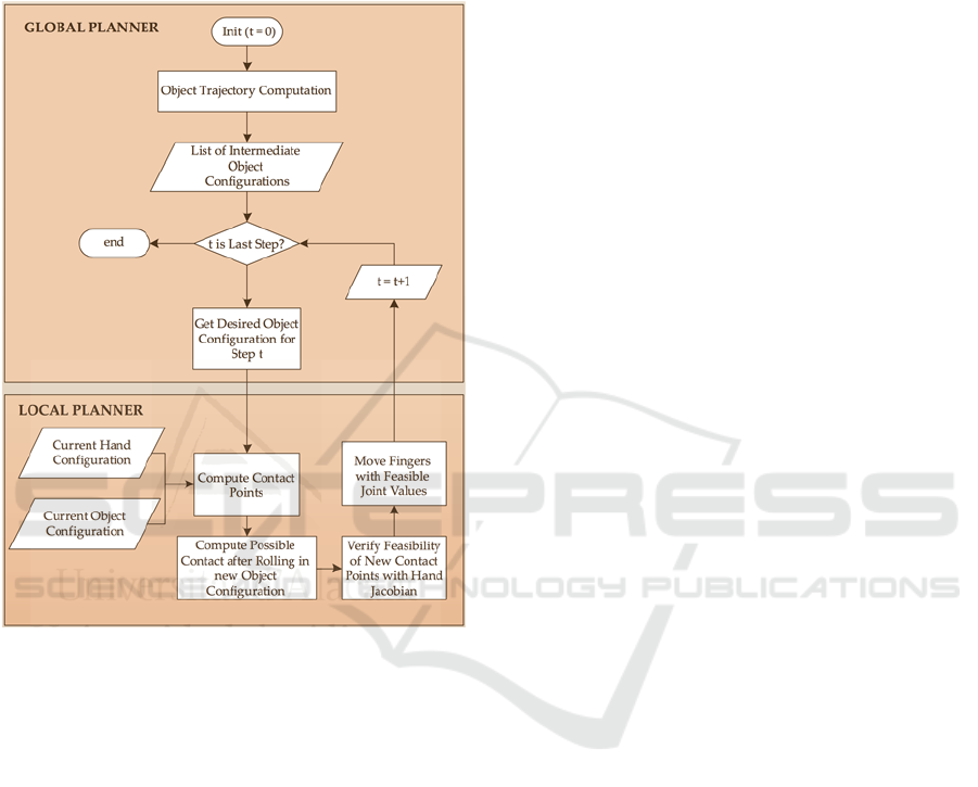
Figure 4: Diagram of the geometric manipulation planner.
where v
C
= [v
Cl
T
… v
Ck
T
]
T
is the vector which
contains all the contact points velocities.
Also, a camera is fixed at the workspace in an
eye-to-hand configuration in order to observe a set
of features located at the surface of the manipulated
object. The kinematics formulation has been studied
in (Jara, 2014).
3.2 The Geometric Manipulation
Planner
The planner receives as input a given grasp and a
desired final configuration of the object. From these
input parameters, the planner has to compute the
changes of the fingers joint angles that drive the
object from the initial grasp towards the final desired
configuration. During this process, the planner
should take into account not only the maintenance of
the contacts of all the fingers which are touching the
object in the initial grasp configuration but also the
kinematic restrictions of the fingers caused by the
limits of their workspaces. The planner has been
organized in two main levels: a global planner and a
local planner shown in the Figure 4.
The main goal of the global planner is to obtain a
group of intermediate object configurations which
are able to join the initial state of the object with its
final state by applying affine transformations.
The local planner is responsible for computing
the movements of the fingers which have to be
applied in order to move the object from the current
configuration to the desired intermediate
configuration. Firstly, it determines the current
contact points between the object and the fingers and
the corresponding pair of contacting primitives.
Secondly, it supposes that the object is in the desired
intermediate configuration and it computes all the
possible variations of the contact points. Thirdly, it
uses the pseudo-inverse of the Jacobian of each
finger in order to verify which contact
configurations are kinematically feasible. Finally,
the local planner moves the fingers towards the
feasible configuration which involves a smaller joint
rate so that the movements of the fingers are
minimized. When these movements are executed,
the global planner will recover the control of the
planner in order to process the next intermediate
object configuration (Corrales, 2011).
4 RESULTS AND FUTURE
WORKS
Figure 5 shows the target used for testing the
prototype: a soda can. We are currently working on
automatic detection of the target by computer vision
using the images obtained by the drone during a
planned flight. Our research group have some
experience in detecting objects from aerial images
(Alacid, 2016). In this paper, we assume that the
location of the object has already known.
The drone lands in this location and then the
robotic hand can grasp de target object. For grasping
we use the planner presented in section 3. Figure 6
shows how the drone is landed and then the allegro
hand grasps the object. Next, the drone can take off
in order to transport the object to the destination.
More detailed pictures of the grasping task can
be seen in Figure 7 and Figure 8.
We are now working on more complex tasks, when
a dexterous manipulation is necessary and it would
be impossible to do with a simple gripper. In these
cases it is essential to use a robotic hand.
ICAART 2017 - 9th International Conference on Agents and Artificial Intelligence
156
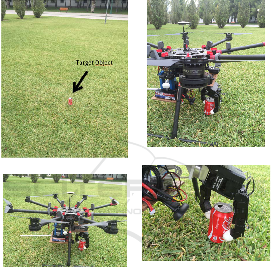
Figure 5: The target object.
Figure 6: The drone with the Allegro hand grasps the
object.
In the future we will also study the grasp stability
during takeoff and flight, when there would be
external forces that must be countered, for example
(Backus, 2014; Korpela 2011).
5 CONCLUSIONS
In this paper we describe a novel aerial manipulation
system (DM-UAV) composed of a drone with an
robotic hand. For this contribution, it is assumed that
the object position is known so the drone flights to
.
Figure 7: Grasping detail.
Figure 8: Grasping detail.
this position and lands, then the robotic hand can
grasp the target object. After of that, the drone can
take off in order to transport the object to other
location. The structure of a first prototype, the
configuration of the robotic hand and its tactile
sensors, and the grasping planner has been described
in the manuscript with more detail.
The proposed system can be used for different
applications, f.e. agriculture, to clean the trash on the
field, to eliminate contaminate objects, etc.
In the literature, there is not any similar
experience, considering a drone with a complex
robotic hand in order to make dexterous aerial
manipulation (DM-UAV). This paper describes the
DM-UAV: Dexterous Manipulation Unmanned Aerial Vehicle
157

first step of our research, but we continue working to
make more complex manipulation tasks.
ACKNOWLEDGEMENTS
Research supported by the Valencia Regional
Government, PROMETEO/2013/085.
REFERENCES
Alacid, B.; Gil, P. An approach for SLAR images
denoising based on removing regions with low visual
quality for oil spill detection SPIE Remote Sensing
2016. Edinburgh. 2016.
Backus, Spencer B., Lael U. Odhner, and Aaron M.
Dollar. "Design of hands for aerial manipulation:
actuator number and routing for grasping and
perching." 2014 IEEE/RSJ International Conference
on Intelligent Robots and Systems. IEEE, 2014.
Corrales Ramón, J. A. PhD. Safe Human-Robot
Interaction Based on Multi-sensor Fusion and
Dexterous Manipulation Planning. 2011.
Courtney E. Doley, Justin J. Bird, Taylor A. Isom, C. J.
Johson, J. C. Kallman, J. A. Simpson, R. J. King, J.
Abbott, M. A. Minor. Avian-inspired passive perching
mechanism form robotic rotorcraft. IEEE/RSJ
International Conference on Intelligent Robots and
Systems, pp. 4975-4980, 2011.
Jara, C. A.; Pomares, J.;Candelas, F. A.; Torres, F. Control
Framework for Dexterous Manipulation Using
Dynamic Visual Servoing and Tactile Sensors’
Feedback. Sensors Vol. 14 (1). pp.1787-1804. 2014.
Korpela, Christopher M., Todd W. Danko, and Paul Y.
Oh. "Designing a system for mobile manipulation
from an unmanned aerial vehicle." 2011 IEEE
Conference on Technologies for Practical Robot
Applications. IEEE, 2011.
Korpela, C. M.; Danko, T. W.; Oh, P. Y. MM-UAV:
Mobile manipulating unmanned aerial vehicle. Journal
of Intelligent & Robotic Systmes, Vol. 65, 1, 93-101.
2012.
Murray, R.; Li, Z.; Sastry, S. A Mathematical Introduction
to Robotic Manipulation; CRC Press: Boca Raton, FL,
USA, 1994; pp. 211–265.
Orsag, M. Mobile Manipulating Unmanned Aerial vevicle
(MM-UAV): Towards Aerial Manipulators. Faculty of
Electrical Engineering and Computing, University of
Zagreb-Croatia. 2012.
Tegin, J.; Wikander, J. Tactile sensing in intelligent
robotic manipulation—A review. Ind. Robot 2005, 32,
64–70.
Thomas, J.; Polin, J.; Sreenath K.; Kumar, V. Avian-
inspired grasping for quadrotor micro uavs.
Proceedings of ASME International Design
Engineering Technical Conferences & Computers and
Information in Engineering Conference. 2013.
Thomas, J.; Loianno, G.; Daniilidis, K.; Kumar, V. Visual
Servoing of Quadrotors for Perching by Hanging from
Cylindrical Objets. IEEE Robotics and Automation
letters, Vol. 1, 1, 57-64. 2016.
ICAART 2017 - 9th International Conference on Agents and Artificial Intelligence
158
