
Modeling Semantics for Building Deconstruction
Enrico Marino
1
, Federico Spini
1
, Alberto Paoluzzi
2
, Danilo Salvati
2
, Christian Vadalà
2
,
Antonio Bottaro
3
and Michele Vicentino
3
1
Department of Engineering, Roma Tre University, Rome, Italy
2
Department of Mathematics and Physics, Roma Tre University, Rome, Italy
3
GEOWEB S.p.A., Rome, Italy
Keywords:
Building Modeling, BIM, Deconstruction Semantics.
Abstract:
In this paper we discuss the motivation, the technology, the design and the use-model of a novel web service
for quantity surveyors, aiming to exploit virtual and augmented reality methods to implement a “zero waste”
model, i.e. a new design paradigm where the waste materials from demolition become resources for recon-
struction. The goal of this project is to provide virtual/augmented reality tools through quick modeling of
buildings and their fast augmentation with semantic content.
1 INTRODUCTION
A tendency to minimize the humanization of new ter-
ritories and to push for reusing already built accom-
modation or accommodation which has fallen into
disuse has become a pressing need in advanced so-
cieties. We have to integrate the “zero energy” model
(each building has to produce the same amount of en-
ergy that it consumes) with the “zero waste” model,
i.e. a new design paradigm where the waste materi-
als from demolition become resources for reconstruc-
tion (Altamura, 2012). Building, contract, and design
processes need to be renewed to take account of envi-
ronmental concerns.
To reduce the impact of construction projects on
the environment, the design needs to take the issue of
building materials into consideration. Public admin-
istrations need suitable tools for the calculation and
the control of reused or disposed materials. The new
tools should handle the digital processing of materi-
als throughout the project life cycle, supporting new
project requirements such as: Design for Deconstruc-
tion, Design for Recycling and Design for Waste.
In particular, a building life cycle, underpinned by
a construction process which envisages cycles aligned
to natural phenomena is the focus of this paper.
In this work
1
we propose solutions that serve to
close the circle of the building life-cycle, moving
1
Partially supported by grant from GEOWEB S.p.A., a web
service company owned by Sogei S.p.A. and CNGeGL —
the ICT company of the Italian Ministry of Economy and
away from a traditional linear response with exces-
sively high consumption energy rates (cradle to grave)
and towards the reuse of materials in deconstruc-
tion/reconstruction (cradle to cradle), supported by
computer aided selective demolition process.
All restructuring cycles of buildings should en-
visage de-construction and re-construction steps, tar-
geted towards the replacement of materials in order
to achieve greater efficiency. The handling of these
materials requires appropriate encoding both for the
disposal, according to EWC (European Waste Cat-
alogue) codes, and for the planning and design of
new buildings, following BIM (Building Information
Modeling) methodology. For this purpose we need
geo-referenced scenes of augmented reality based on
fast, easily navigable and measurable 3D models.
We already have excellent knowledge about con-
struction costs (from scratch) but little is known about
replacement rates (complete selective demolition). A
modern selective demolition process requires human
intervention, with high insurance costs due to the dan-
ger involved for those working in these activities.
This latter point demands an alternative to human
effort in these process. We suggest that automated
robots could replace human effort; drones could op-
erate in a semantically familiar context and give real-
time updates as the reality contextually changes.
We believe, therefore, that there is a big need
Finance and the Italian National Board of Quantity Sur-
veyors, respectively.
274
Marino E., Spini F., Paoluzzi A., Salvati D., VadalÃ
˘
a C., Bottaro A. and Vicentino M.
Modeling Semantics for Building Deconstruction.
DOI: 10.5220/0006227902740281
In Proceedings of the 12th International Joint Conference on Computer Vision, Imaging and Computer Graphics Theory and Applications (VISIGRAPP 2017), pages 274-281
ISBN: 978-989-758-224-0
Copyright
c
2017 by SCITEPRESS – Science and Technology Publications, Lda. All rights reserved

for modern and easy-to-use modeling frameworks for
building deconstruction in the AEC (Architecture,
Engineering and Construction) industry, to enable an
augmented reality through semantic recognition by
computer vision and by photogrammetric precision
up to centimetric definition. Such virtual/augmented
reality tools require both fast 3D building modeling
and augmentation with semantic content, in order to
be controlled in almost real time: this real challenge
is also required by the future development of the In-
ternet of Things.
In this section we have discussed the motivation of
the project described in this paper. The remaining sec-
tions are organized as follows. Section 2 introduces
a more technical viewpoint about the state of decon-
struction topics in Europe and in Italy. Section 3 de-
scribes the client application and the proposed work-
flow for quantity surveyors. Section 4 illustrates the
framework architecture. Section 5 shortly recalls the
methodology, programming style and computational
environment of our geometric programming approach
to solid modeling. In the conclusion section we out-
line the work to be done and provide our forecast
about possible developments.
2 DESIGN TO DECONSTRUCT
Waste management is an issue that in recent decades
has become increasingly important, considering its
economic, environmental and energy impact.
2.1 Regulatory Framework
The European Community has defined standards
[EU 98/2008, 1357/2014] and goals (qualitative and
quantitative) that Member States must comply with
through the enactment of national regulations and the
definition of economic instruments.
Waste disposal, with direct and indirect costs in-
volved, is enforced by Construction and Demolition
activities. In EWC, waste from the demolition of
buildings [955/2014 EU] are identified as class 17
– Construction And Demolition Wastes. This clas-
sification allows a correct identification of both the
waste generated from adoptable demolition modes,
and the waste produced by actions of re-use, recycling
or landfilling.
The regulatory framework for waste management
is far from clear, in particular in the Italian national
context. Despite its direct and indirect costs, the land-
fill is often preferred rather than risking administra-
tive or criminal penalties for failure to comply with
unclear rules.
2.2 Proposed Approach
Given this cumbersome regulatory framework, our
project is promoting the use of simplified IT tools to
support the deconstruction. In particular, a quick sim-
plified geometric modeling of the building allows for
integration of a semantic description of component
parts and their materials. Virtual/Augmented Reality
strongly helps overcome the administrative difficul-
ties, provided the correct identification of the waste
produced. This approach will increase the adoption
of virtuous actions, namely the recovery and reuse.
In particular, a geometric modeling of the building
allows to identify: (a) cost / income resulting from al-
ternatives of recycling / re-using instead of disposal;
(b) the composition and integration of information
useful to the planning of construction activities; (c)
achievement of the thresholds of reuse / recovery re-
quired by the regulations; (d) ability to economically
compare different options.
We started by considering the SMARTWaste sys-
tem (Hurley, 2002). Their approach allows to derive
estimates of the quantities of materials by providing a
description of the type of building and the area where
it was built. With this information, the forms that pro-
vide an aggregated representation of the data of inter-
est are automatically filled.
Our approach to deconstruction conversely pro-
vides both a geometric modeling of building subsys-
tems and components and a semantic annotation with
construction materials, like a sort of simplified BIM.
As a matter of fact, our national construction indus-
try is strongly heterogeneous, so that we need a pretty
detailed modeling to obtain enough accurate informa-
tion. One vantage point of this approach is an incre-
mental iterative character, where each modeling stage
may be followed by validation of partial costs.
A complete report about using BIM as a building
deconstruction approach is provided by (Galic et al.,
2014). A study on the usage of BIM as a support for
Design for Deconstruction is carried on by (Akinade
et al., 2015). In this setup, on the contrary to what
holds for us, deconstruction has to be a major concern
starting from the beginning of the building design.
A large corpus of specialized literature exists
about BIM for existing buildings. A very interest-
ing review paper, discussing hundreds of references
is (Volk et al., 2014). Its abstract states that: “While
BIM processes are established for new buildings, the
majority of existing buildings is not maintained, re-
furbished or deconstructed with BIM yet. Promising
benefits of efficient resource management motivate
research to overcome uncertainties of building condi-
tion and deficient documentation prevalent in existing
buildings.”
Modeling Semantics for Building Deconstruction
275
The Metior (from Latin: to measure or esti-
mate) project, introduced in this paper, is exactly
aiming to overcome such difficulties, via (a) the de-
sign and implementation of a web service providing a
strongly simplified user-interface, designed for quan-
tity surveyors; (b) storing a growing database of tem-
plate plugins for more geometrically complex build-
ing parts; (c) using an extensible geometry engine and
server based on decades of research; (d) offering flex-
ible semantic additions via specialization of IFC (In-
dustry Foundation Classes (ISO, 2013)) classes asso-
ciated to building subsystems and parts.
Metior specifically targets quantity surveyors. In
fact, although large sites to be deconstructed are op-
erated by main contractors, where skills and spe-
cific tools might be widely available and already
used, most of deconstruction activities, and hence the
largest amount of waste material produced, are man-
aged by quantity surveyors from small or medium
companies — or even by single professionals. Such
kind of firms may need to be supported with tools
where the complexity, both bureaucratic and techni-
cal, have to be hidden although correctly managed.
3 DECONSTRUCTION APP
A deconstruction oriented to the maximum reuse of
materials must be supported by a workflow that guides
the user towards estimating the costs of the process.
The aim is the determination of building demolition
costs, depending also on transportation and disposal
of materials.
3.1 Workflow
Project Definition. The first phase of the modeling
process is a gross description of the building, in or-
der to provide basic clues for a correct attribution of
the semantic attributes. In particular, we ask for: the
apparent age, the style of construction, the historic
use register, and the geolocation. The estimated age
and the style of construction are used to determine
the needed data about the used materials; the record
of use destinations allows to reconstruct the hazard
notes of the items to be disposed of; geolocation fi-
nally allows to find out the recycling facilities closest
to the site.
Building Modeling. The user describes the con-
struction using some predefined classes of elements,
either instantiating some predefined parametric plug-
ins or through wire-frame input of 2D layouts. First
is defined the building skeleton (backbone), i.e. the
set of beams and columns or load-bearing walls, pro-
viding the structural grid. On its horizontal sections,
the user specifies the exterior and interior walls (ver-
tical enclosure and partitions), on which the fixtures
are positioned (horizontal communications). Ceilings
and floors (horizontal partitions) are instead automat-
ically generated from the topology (1-boundary) of
the 2-skeleton of the floors (subsets of 2-cells). Fi-
nally, various elements such as stairs, elevators (ver-
tical communications), foundations and roofs (hori-
zontal enclosures) are placed, using ad-hoc templates
interactively provided by Metior’s plugin server, for
appropriate sizing and part dimensioning.
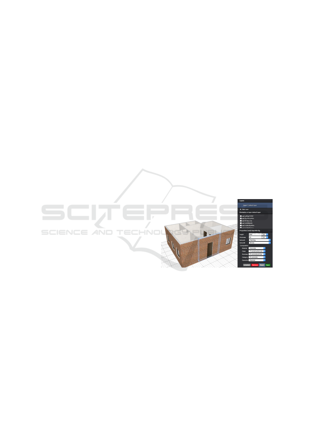
Semantic Annotations. At this stage (see Figure 1)
the previously inserted elements are annotated seman-
tically by means of references to database of mate-
rials, including densities. The annotation may con-
sists of one or more materials, including percentages.
For disposal control imposed by regulations, the user
should assign one / more EWC codes and degrees of
dangerousness (see Section 2.1). In this stage it is also
assigned a pair of links that refer to the time schedule
for disposal of building components.
Figure 1: Graphical interface for semantics annotation.
Augmented Reality Visualization. After modeling
and attribution of semantics to components, the quan-
tity surveyor can validate the entire model by spatial
merging into a 3D point cloud (see Figure 2) previ-
ously obtained by using flying drones for the exte-
rior, or 3D laser scanners for the interior. In this way
one can assess the adhesion of the modeled building
structure to reality, possibly retracing to some previ-
ous step if the result is still not satisfactory.
3.2 Process Output
Once the work is done and the model geometry is
validated, the application provides a final report. In
particular, the final report will allow the quantity sur-
veyor and/or the other professionals involved in the
GRAPP 2017 - International Conference on Computer Graphics Theory and Applications
276
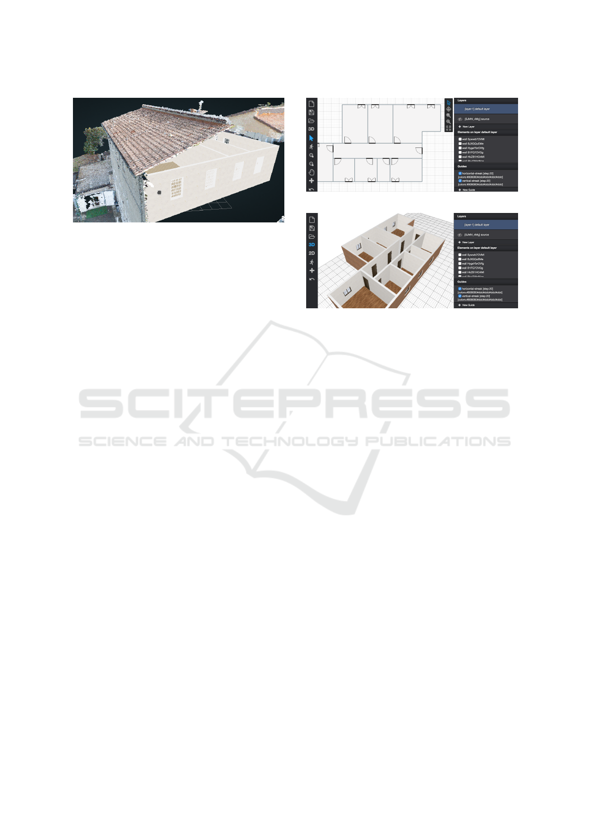
Figure 2: A model inside a point cloud.
deconstruction design team, to determine whether
the decision taken is convenient both economically
and/or environmentally.
The final report consists of four documents. (i) An
estimate of volumes and weights of materials, com-
puted by appropriate integration calculations, based
on the geometry of components and annotations de-
fined on them. (ii) An estimate of demolition costs,
including disposal and recovery. Starting from vol-
umes and densities of materials, and from EWC codes
and hence the mode of disposal, it is estimated the
cost of the contribution to landfills. (iii) The trans-
portation costs to move the materials to the closest
landfills, taking into account the geographical posi-
tion of the building, and by calculating the most con-
venient road routes. (iv) An estimate of the expected
time for the complete demolition of the building, lo-
cated on a Gantt chart. Semantic annotations are also
used to generate a schedule of the demolition activi-
ties by means of a PERT program.
4 DESIGN AND ARCHITECTURE
Workflow and requirements described in the previous
section have been received in a prototypal application
serving as proof of concept. With the aim of maxi-
mize accessibility for quantity surveyors, it is strongly
web based and runs in all modern browsers. It is built
using React by Facebook and the unidirectional data
flow design pattern (Abramov, 2016): it ensures the
best code maintainability and debuggability by cen-
tralizing access to the application state in a single con-
troller.
4.1 UI and User Experience
The web application presents itself as a simplified
CAD software, where the user interface comprises
three main areas of interaction: toolbar, canvas and
sidebar, as shown by Figures 3 and 4.
Figure 3: Metior user interface: 2D canvas.
Figure 4: Metior user interface: 3D canvas.
From the toolbar the user can access functionali-
ties related to: project life cycle (new, save, load);
project editing (show-catalog); view/interaction
mode switching (2D, 3D); interaction mode changing
(selecting, pan, zoom).
The canvas is the area in which the user can in-
teract with actual model data. It supports two dif-
ferent views and interaction modes. In 2D-mode the
model is displayed as a 2D projection from the top,
and the interaction consists of element insertion, se-
lection and editing (according to specific plugin inter-
action prototype, see Section 4.2). In 3D-mode a 3D
model can be inspected and navigated, respectively
via trackball or first-person interaction style, while
object picking allows for element selection.
The sidebar shows the properties of the currently
selected element. In the properties panel it is possible
to view the description of the element, to add/remove
metadata, and to modify any property. The latter is
the interaction mode that allows the user to associate
semantic annotations to every part of the model.
4.2 Plugin-architecture
The application has been designed to provide a small
set of core interaction functionalities and to encapsu-
late the generation logic for architectural components
(from the very basic to the most articulated) into spe-
cific plugins.
A plugin is a software component that can be
seamlessly integrated into the system in order to ex-
tends its capabilities. In Metior, a plugin represents
an architectural element that extends the Building In-
formation Model design. Technically, a plugin repre-
Modeling Semantics for Building Deconstruction
277
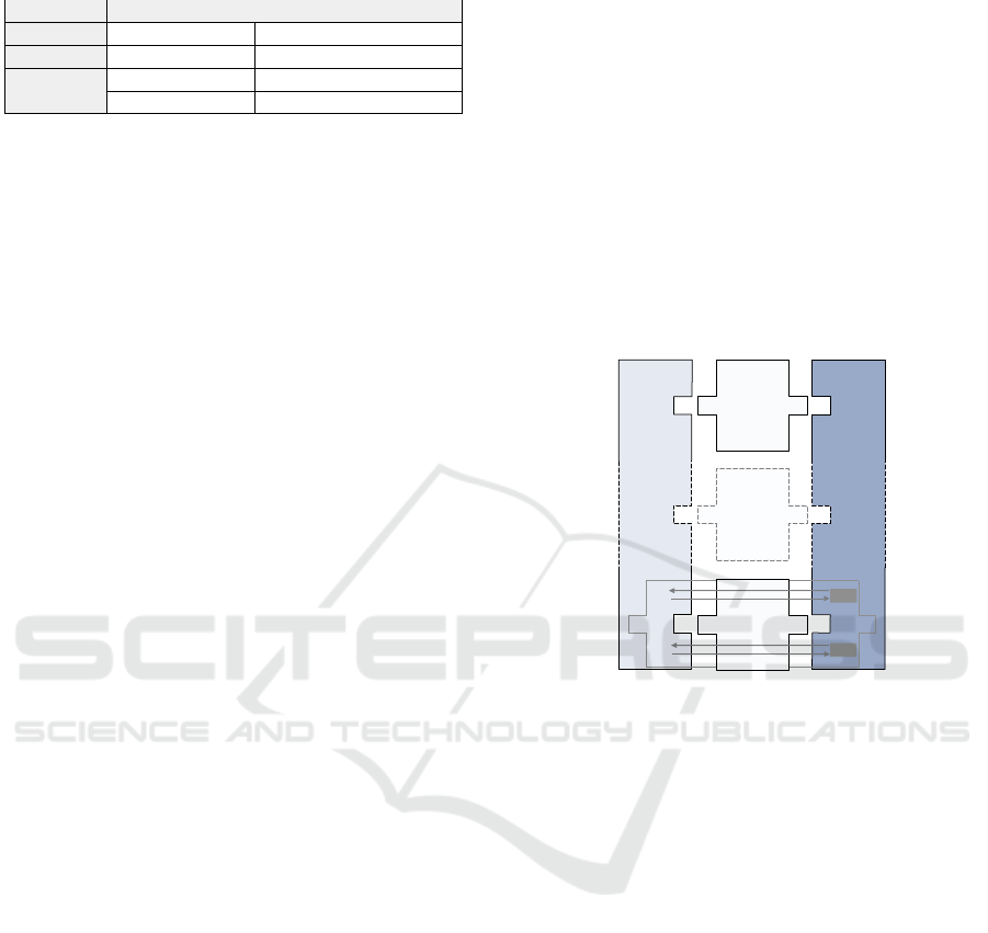
Table 1: Plugin examples according to taxonomy.
inside over / free
linear pipe electrical-conduit
ver. area window, door wall
hor. area light-panel ground, ceil
volume pillar staircase
sents a prototype (namely a “class” in Object Oriented
Programming) of a construction element that can be
inserted (“instantiated”) into the canvas, thus defining
a new element, i.e. a new component of the model.
Plugin Definition. A plugin is described by the fol-
lowing eight properties: (1) a unique name; (2) a
description; (3) a set of metadata; (4) the occupa-
tion type (one among linear, area or volume); (5) the
placement type (inside or over); (6) a set of specific
properties mapping the semantic to associate to the
plugin; (7) a generating function that returns the 2D
representation of the element in SVG format, to be
used in the 2D-mode; (8) a generating function that
returns the 3D representation of the element in OBJ
format, to be used in the 3D-mode.
Plugins Taxonomy. The plugins can be organized
according to occupation type and placement type.
In the occupation type three different kind of plu-
gins can be identified: linear, area or volume plugins.
The linear ones extend in one dimension (unless a ra-
dial thickness) (e.g. hydraulic lines, electrical cables).
The area plugins extend in two dimensions (unless a
linear thickness), (e.g. separation elements). They
can be divided into horizontal area (e.g. floor and
ceil), and vertical area, (e.g. walls). The volume plu-
gins extend in three dimensions. They can be fixed
volume, (e.g. a piece of furniture) and scalable vol-
ume, that can be scaled (proportionally or not), (eg.
pillars, staircases).
The occupation type determines a different way to
instantiate and to insert the plugins into the canvas.
In particular, in 2D-mode, linear plugins are inserted
drawing lines by mean of a drag&drop interaction; the
area plugins are inserted drawing the bounding-box
of the element by mean of a drag&drop interaction;
the volume plugins are inserted picking the position of
the element by mean of a point&click interaction, and
adjusting their dimensions modifying the bounding-
box by drag&drop.
The placement type determines if the element can
be inserted into the canvas in a specific point occu-
pied or not by other elements. In other words, the
placement type determines the relationship between a
new instance of a plugin and instances of other plu-
gins previously added to the model. The relationship
can be of two kind: inside or over. Plugins belonging
to the inside category can be added only inside other
element (that can be linear, area or volume); e.g., a
“window” is a “volume inside vertical area” element,
while an “hydraulic line” is a “linear inside horizon-
tal area” element. Plugins of the over category can be
added only over other elements (of any type); e.g., a
“pillar” is a “volume over horizontal area” element,
while an “electric panel” is a “volume over vertical
area” element.
In the design phase, an element that doesn’t meet
the placement constraints defined by the placement
type is notified by the system as a visual warning,
showing its bounding-box in semi-transparent blinked
red color.
HTML5
WebGL
SVG
Client
PyPlasm
LAR
Server
parameters
parameters
JSON + .svg
Plugin - wall
Plugin
pitched-roof
Plugin
...
3Dgf
2Dgf
JSON + .obj
Figure 5: Client/Server architecture for server-side model
generation.
Plugin Specific Properties. Each plugin has a set
of specific properties of the building elements it rep-
resents. Each property is defined by (1) a name, (2)
a type, such as “number”, “text”, “boolean”, or “cus-
tom”, and by (3) a value. According to its type, each
property value can be inserted in different ways. For
example, a boolean property value is set through a
checkbox, while a textual property is set through a
text box.
The system is designed to accept custom kinds of
property. A custom property is required to define the
component of the UI that permits the user to insert its
value. For example, a “color” property can be intro-
duced by defining a UI component composed by three
text boxes (one for each RGB components), while a
“length” property can be introduced by defining a UI
component including a text box for the value and a
drop-down menu for the unit of measure.
The specific properties of an element can be edited
in the relative panel in the sidebar, once the element
is selected in the canvas.
GRAPP 2017 - International Conference on Computer Graphics Theory and Applications
278
4.3 Plugin Catalog
It is pivotal to provide the system users with a rich
catalog of plugins, to cover all the basic as well as
the most advanced modeling requirements. Table 1
reports examples of plugins arranged according to the
taxonomy introduced in Section 4.2.
4.4 Server-side Models Generation
Both the 3D and 2D model generations have been
designed as asynchronous. The actual result of the
invocation of a generating function is not the gener-
ated model itself, but rather a promise of the expected
result. Such a design choice is important since the
computation for model generation may require some
while. In the meantime the user must be able to in-
teract with the interface, which in turn must remain
responsive. Relying on this architecture, generation
of the models can be easily delegated to a server (as
shown in Figure 5), thus relieving the client from the
burden of onerous computations. The server exposes
a REST-like HTTP-based JSON API to the client.
The plugins span from the client to the server, since
the 2D and 3D generating functions ( 2Dgf and 3Dgf )
defined by the plugin are actually executed on the
server, as shown in Figure 5.
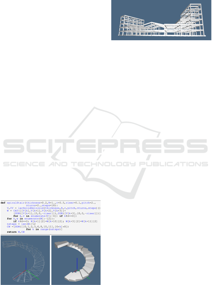
4.5 Plugin Examples
Figure 6 shows the plugin used to generate concrete
spiral stairs, with steps from coded update of a poly-
hedral approximation of a larSolidHelicoid(),
minor and major radiuses (r and R) and int number
of steps. The nturns float is in radians.
Figure 6: (a) The generating function of a strongly parame-
terized spiralStair; (b) default spiralStair.
Figure 7: A spatial concrete frame generated, from a small
.csv file, by the pyplasm plugin spatialFrame.
The model generated by a plugin for automatic
generation of spatial concrete frames is shown in Fig-
ure 7. In this case the user interface produces a
small .csv file specifying, for each component pla-
nar frame, the grid-like pattern of members, the 2D
sections of columns and beams, and the proper roto-
translation, i.e. the four numbers α, tx, ty, tz that in-
stantiate each frame in the reference frame of the
previous one. The connecting beams are automati-
cally generated, and the various classes of members
(foots,timbers,columns,linkBeams) are made
available for interactive picking and possible local
modification of geometry and/or materials by the sys-
tem user, and of course, for quantity surveying.
5 SOLID MODELING
The server-based geometric core of the modeling ar-
chitecture is based on a set of python libraries, includ-
ing pyopengl, scipy, pyplasm and larlib, that pro-
vide our current implementation of the LAR (Linear
Algebraic Representation) scheme for solid model-
ing, 3D imaging and mesh representation, and which
is briefly described in the following.
5.1 Linear Algebraic Representation
LAR is a general-purpose representation scheme (Di-
Carlo et al., 2014) for geometric and solid modeling
introduced recently. The domain of the scheme is pro-
vided by dimension-independent cellular complexes,
while its codomain is that of sparse matrices, stored
using either the CSR (Compressed Sparse Row) or the
CSC (Compressed Sparse Column) scipy’s memory
format. The LAR polyhedral domain coincides with
complexes of connected d-cells, even non-convex
and/or including any number of holes.
The very general shape allowed for cells makes
the LAR scheme notably appropriate for solid model-
ing of buildings and their components. E.g., the whole
frontage of a construction can be described as a sin-
gle 3-cell of its solid model. Also, the algebraic foun-
dation of LAR allows not only for fast queries about
Modeling Semantics for Building Deconstruction
279

incidence and adjacency of cells, but also to resolve—
via fast SpMV computational kernels—the boundary
extraction of any 3D subset of the building model.
It is worth noting that LAR provides a direct
management of all subsets of cells and their physi-
cal properties trough the linear spaces of chains in-
duced by the model partitioning, and their dual spaces
of cochains. The linear operators of boundary and
coboundary between such linear spaces, suitably im-
plemented by sparse matrices, directly provide, de-
pending on the dimension of the mapped spaces, the
discrete differential operators of gradient, curl and di-
vergence, while their product gives the Laplacian (Di-
Carlo et al., 2009).
5.2 Geometric Computing of Shape
Our computational environment is strongly ori-
ented towards the most general parametric model-
ing of component shapes of buildings. This atti-
tude is produced by two Python libraries, that pro-
vide a dimension-independent algebraic calculus with
shapes (pyplasm) and their representation in the LAR
scheme (larlib).
PLaSM (Paoluzzi et al., 1995; Paoluzzi et al.,
2003), which stands for Programming Language for
Solid Modeling, is a geometry-oriented extension of
Backus’ FL language (Backus, 1978; Backus et al.,
1989). PLaSM is a project developed in the nineties in
the framework of Building Technologies Project (“PF
Edilizia”) of the Italian National Research Council.
The pyplasm module (2006) is the C++ porting of
PLaSM to Python via SWIG wrapping.
On top of the Scipy/Pyplasm stack we started
(2012), using literate programming methods, to build
a set of software modules, named larlib, and us-
ing the LAR scheme. This library supports topolog-
ical queries and physical properties of meshes and
complexes, including integration of polynomials over
the boundary of any chain of cells. For interactive
visualization it relies on the pyplasm viewer, based
on OpenGL. A porting of the most engaging parts
of larlib to Julia, the last-generation programming
language for scientific computing (Bezanson et al.,
2014) started very recently, with the purpose of taking
advantage of the great computational efficiency and
parallelism of Julia in more demanding applications.
5.3 Plugin Server Framework
Our building deconstruction framework has a web-
based client-server architecture, discussed in Sec-
tion 4. Metior, the web client application, is illus-
trated in Section 3. The server-side of the framework,
discussed in this section, is a plugin server written in
Python, which capitalizes on the stack of geometric
programming tools described above.
The Metior user quickly develops a 3D hierarchi-
cal assembly of different parts of the building en-
velope, as well as the horizontal and vertical parti-
tions, using very simple 2D drawing tools. The more
geometrically complex parts of the construction are
conversely set up by user picking from context-based
boards of predefined plugin templates, that are Python
scripts (see Figure 6) generating solids models which
are interactively dimensioned, either using 2D draw-
ing tools, or by user’s numeric input from keyboard.
Of course, our list of plugin templates embraces
most of building parts that are not manageable for
quick shape input via 2D interaction. In particular, the
picking boards include templates for planar concrete
frames, spatial building frames, building foundations,
roofs and stairs of different types, attics and dorm-
ers, fireplaces and fitted wardrobes, shover cabins and
sanitary equipments, doors and windows, etc.
It is worth noting that, by virtue of the great
expressiveness of the PLaSM operators and its
functional style of programming and dimension-
independent geometry, the development of a new plu-
gin template is very easy even for non-experienced
programmers, and usually requires a tiny amount of
time and code, that may range between 4-8 hours, and
between 10-100 lines of Python/pyplasm code.
Two important points we would like to remark
are: (a) the great expressive power of the geo-
metric language, strongly empowered by currying,
i.e. by translating the evaluation of a function—
that takes either multiple arguments or a tuple of
arguments—into evaluating a sequence of functions,
each with a single argument; (b) the ease of devel-
opment. Python/pyplasm is used even to teach ge-
ometric programming to K12 students (Solin, 2016)
(see ??https://nclab.com/3d-gallery/). Sev-
eral plugin templates used by Metior were developed
in class by students, in the framework of the computer
graphics course being taught by one of authors.
6 CONCLUSIONS
In this paper we have introduced a software architec-
ture and framework to be used in design for building
deconstruction. The immediate goal is to provide an
advanced web-service for quantity surveyors, called
to make reliable and accurate estimates of economic
and environmental returns from unused buildings, ac-
cording to new waste material regulations and to poli-
cies for land use control.
GRAPP 2017 - International Conference on Computer Graphics Theory and Applications
280

The reader may have easily seen that the Metior
framework can be used as a simplified BIM instru-
ment for renovation projects in existing buildings, and
even for new design projects. Metior, currently in pro-
totype development, is based on advanced technolo-
gies for web services and applications, and on recent
developments in geometric computing. It is worth-
noting that Metior might provide a basis for more
demanding undertakings, in particular in a national
scene in strong need for new large programs of reno-
vation and seismic adaptation of its built heritage.
REFERENCES
Abramov, D. (2016). Redux: predictable state container for
javascript apps. http://redux.js.org/. Accessed: 2016-
11-09.
Akinade, O. O., Oyedele, L. O., Bilal, M., Ajayi, S. O.,
Owolabi, H. A., Alaka, H. A., and Bello, S. A. (2015).
Waste minimisation through deconstruction: A bim
based deconstructability assessment score (bim-das).
Resources, Conservation and Recycling, 105:167–
176.
Altamura, P. (2012). Gestione eco-efficace dei materiali
da costruzione nel ciclo di vita del fabbricato. PhD
thesis, Sapienza Università di Roma. (in Italian).
Backus, J. (1978). Can programming be liberated from the
von Neumann style?: a functional style and its algebra
of programs. Commun. ACM, 21(8):613–641.
Backus, J., Williams, J., Wimmers, E., Lucas, P., and Aiken,
A. (1989). FL language manual, parts 1 and 2. Tech-
nical report, IBM Research Report.
Bezanson, J., Edelman, A., Karpinski, S., and Shah, V. B.
(2014). Julia: A fresh approach to numeric comput-
ing.
DiCarlo, A., Milicchio, F., Paoluzzi, A., and Shapiro, V.
(2009). Chain-based representations for solid and
physical modeling. Automation Science and Engi-
neering, IEEE Transactions on, 6(3):454 –467.
DiCarlo, A., Paoluzzi, A., and Shapiro, V. (2014). Lin-
ear algebraic representation for topological structures.
Comput. Aided Des., 46:269–274.
Galic, M., Dolacek-Alduk, Z., Cerovecki, A., Glick, D.,
and Abramovic, M. (2014). Bim in planning decon-
struction projects. eWork and eBusiness in Architec-
ture, Engineering and Construction: ECPPM 2014,
page 81.
Hurley, J. W. (2002). How to smartwaste the construction
industry. In 10th Symposium Construction Innovation
and Global Competitiveness, Conference Proceedings
for the 10th Syposium Construction Innovation and
Global Competitiveness.
ISO (2013). Industry Foundation Classes, iso 16739:2013.
http://www.iso.org/iso/catalogue_detail.htm?csnum
ber=51622. Accessed: 2016-12-29.
Paoluzzi, A., Pascucci, V., and Vicentino, M. (1995). Geo-
metric programming: a programming approach to ge-
ometric design. ACM Trans. Graph., 14(3):266–306.
Paoluzzi, A., Pascucci, V., Vicentino, M., Baldazzi, C.,
and Portuesi, S. (2003). Geometric Programming for
Computer Aided Design. John Wiley & Sons, Inc.,
New York, NY, USA. 815 pages.
Solin, P. (2016). https://nclab.com/3d-gallery/,Creative
Computing Platform: Learn Coding and 3D Model-
ing! Accessed: 2016-11-12.
Volk, R., Stengel, J., and Schultmann, F. (2014). Build-
ing information modeling (bim) for existing buildings
— literature review and future needs. Automation in
Construction, 38:109 – 127.
Modeling Semantics for Building Deconstruction
281
