
A Test Bed Model of an Advanced Handheld Bone Drilling System
Tomislav Staroveski, Zlatko Catlak, Miho Klaic and Toma Udiljak
Faculty of Mechanical Engineering and Naval Architecture, University of Zagreb, Ivana Lucica 5, Zagreb, Croatia
Keywords: Bone Drilling Machine, Autonomous Drilling, Process Monitoring, Adaptive Control.
Abstract: Modern medical drilling systems utilized in bone and joint surgery are characterized with relatively low
level of automation, i.e., with no process monitoring and/or adaptive control characteristics, which could
potentially prevent mechanical and thermal bone damages. The quality of the drilling process depends
solely on the operator skills and tool characteristics. Therefore, a group of research activities have been
focused to the development of an advanced next generation hand-held drilling machine. It should provide
mechanical and thermal monitoring capabilities of the tool and bone, automated tool feed movement with
potential implementation of high-speed drilling regimes, as well as the application of an advanced adaptive
control algorithms for cutting forces and drilling temperature limitation. The system would reduce human
influence in drill guidance by allowing operator to define drilling location and desired tool direction/angle,
while all other activities would be performed autonomously by the machine monitoring and control system.
The test bed platform of such system which will be used in the final prototype shaping is presented in this
paper.
1 INTRODUCTION
Bone drilling interventions have nowadays become
usual and everyday practice in bone and joint
surgery as well as dental surgery. Bone is a complex
biological tissue with organic and mineral elements
whose interactions result in unique mechanical and
thermal properties. In order to avoid additional
mechanical and thermal bone damages, surgeon has
to take a special care concerning drill stability and
bone temperature during drilling process.
Quality of the drilling procedure depends on
several factors such as (Augustin et al., 2011): drill
design (type, number and flutes inclination, cutting
edge and drill point geometry, drill diameter),
machining parameters, drilling depth (cortical
thickness), cooling, drill wear rate, and drilling path
(drill position in relation to the bone).
Those factors can result in high drilling
temperatures and potential thermal osteonecrosis.
Most of them can also cause inadequate hole
geometry and high cutting forces. Higher forces can
cause drill point or cutting edge breakage, or even
complete drill body breakage. This results in
mechanical bone damages and longer postoperative
rehabilitation process.
Clinical practice in bone and joint surgery today
is based on drilling systems characterised with
relatively low level of automation, i.e., with no
process monitoring and/or adaptive control
characteristics. Drill guidance and handling is
completely controlled by the surgeon, and negative
friction or thermal influences are reduced by
applying cooling fluid externally on the bone surface
and drill shaft during the machining process. This
approach has very limited effect on the temperature
reduction because bone chips prevent contact of
cooling fluid with the cutting edges, and bone itself
has very low thermal conductivity (Davidson and
James, 2000.). Review of currently available
scientific papers and patents on handheld drilling
machines reveals the appearance of first solutions in
the form of prototype systems capable of controlling
thrust force and feed drive (Allotta, Giacalone,
Rinaldi, 1997), or advanced medical drills with
integrated sensors (von Freyberg et al., 2013, Hseih,
2012). The rest of the systems proposed in scientific
publications and patent documentation are robotised
concepts (Boiadjiev et al., 2013, Hsu, Lee and Lin,
2001) or systems and algorithms tested only on
laboratory machine tools (for drilling or milling).
Some studies have been performed on existing
commercial drilling machines.
All those systems combine force/torque sensors
190
Staroveski T., Catlak Z., Klaic M. and Udiljak T.
A Test Bed Model of an Advanced Handheld Bone Drilling System.
DOI: 10.5220/0006228601900193
In Proceedings of the 10th International Joint Conference on Biomedical Engineering Systems and Technologies (BIOSTEC 2017), pages 190-193
ISBN: 978-989-758-216-5
Copyright
c
2017 by SCITEPRESS – Science and Technology Publications, Lda. All rights reserved
and/or motor currents, vibration and acceleration
sensors (can be found in newer systems from 2012
and 2013) to identify drill transition between
different type of tissues, drilling depth (i.e., drilling
time) and feed.
Despite the proposed solutions and based on
numerous research studies in the field of medical
drilling, Pandey and Panda, 2013, stated in their
review paper that the development of more precise
automated bone drilling system to minimize human
error is needed.
In that sense, there are several new potential
enhancements of existing drilling systems applied in
bone and joint surgery worth to be studied, which
are related to:
Real-time direct monitoring of drill path, as
well as drill wear rate and drilling temperature
using indirect monitoring techniques,
Drilling process adaptive control based on the
criteria of maximum allowable mechanical
and thermal effects on drill and bone,
Implementation of internally cooled surgical
drills and adequate clamping mechanism,
Application of high-speed drilling regimes to
reduce bone drilling temperature (Shakouri et
al., 2014).
Drilling test bed system suitable for experimental
research of the abovementioned features is proposed
hereinafter. In the following section, a brief
decsription of its mechanical, electrical, control, data
acquisition and signal processing (DSP) elements, as
well as CAD model are presented.
2 TEST BED SYSTEM DESIGN
The mobile drilling test bed system will be
composed of three parts:
Mechanical components and actuators,
Process monitoring sensors,
Control and DSP unit.
2.1 Mechanical Design and Actuators
The mechanical part of the proposed drilling system
is designed to provide:
Compact body with integrated feed drive and
drill guide,
Drilling experiments with or without engaging
automatic feed drive,
Internal cooling option with easily
exchangeable drills,
Installation of multiple process monitoring
sensors placed at the position nearest to the
signal source.
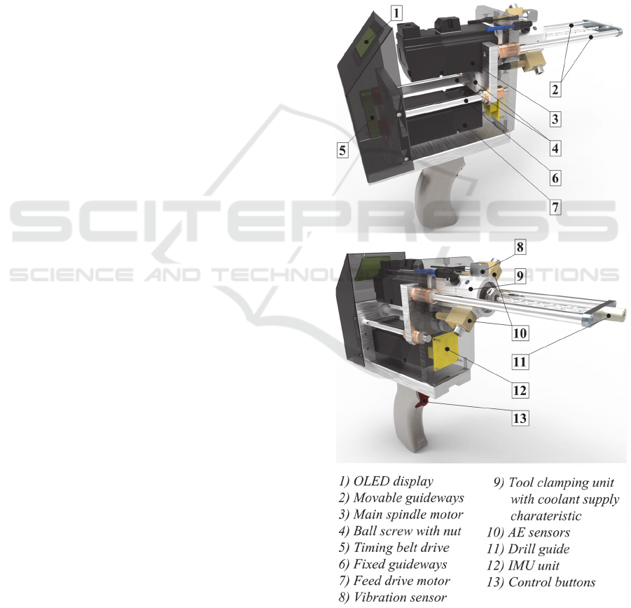
In order to achieve such characteristics, motors
of both drives, i.e., main spindle (3) and feed (7) are
fixed within the machine housing and placed
vertically one below other (Figure 1). Permanent
magnet synchronous servomotor (PMSM) with
integrated incremental encoder type Mecapion APM
SA01ACN-8 will be used for both drives. Their
characteristics are presented in Table 1. PMSM
motors were selected due to the constant torque vs.
RPM ratio over entire working range.
Figure 1: CAD model of the test bed drilling system.
A Test Bed Model of an Advanced Handheld Bone Drilling System
191
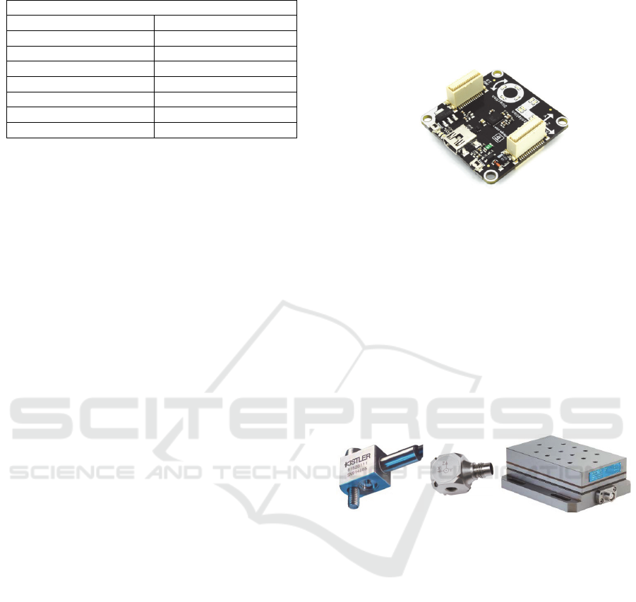
Table 1: Servomotor characteristics.
Servomotor characteristics
Size (H x W x D) in mm 40 x 40 x 125
Output, kW 0.1
Rated RPM/Max RPM 3000/5000
I, Arms 2.38
Rated Torque, Nm 0.318
Max Torque, Nm 0.955
Incr. Encoder, pulses/rev 8196
Moment of inertia, kg m
2
0.045 x 10
-4
Linear motion is performed by a pair of fixed
guideways (6) and a ball screw assembly (4) driven
by a feed motor and timing belt drive (5). Ball screw
nut is connected to the movable main spindle
mounting plate, which is then moved in forward or
backward direction.
Another pair of movable guideways (2), also
connected to the main spindle mounting plate, serves
as drill guide system. The drilling process is to be
operated by pushing the system against the bone and
maintaining the drill guide (11) in contact with the
bone during a drilling cycle.
Tool clamping unit (9) is mounted directly to the
main spindle motor and also serves as coolant
supply and a suitable base for placement of acoustic
emission (10) and vibration sensors (8). The tool is
clamped using collet chuck coupled to the motor
shaft within a sealed cylindrical compartment. The
coolant is fed to the drill through the compartment,
which is fixed in relation to the main spindle motion.
Suitable surgical drills with central 0,4mm coolant
channel have already been manufactured in-house
using Electrical Discharge Machining (EDM)
process.
Acoustic emission (AE) and vibration sensors
are placed in radial directions on the clamping unit,
which is the closest position to the motor spindle
front bearing in order to obtain the highest possible
signal quality. Inertial measurement unit - IMU (12)
was also installed on the device body close to the
centre of its mass.
2.2 Process Monitoring Sensors
Several types of signals will be acquired from the
system/process: drill bit position/path and drilling
machine orientation (IMU), AE, vibrations, cutting
forces, and servomotor currents.
The purpose of IMU, produced by Tinkerforge
type IMU Brick 2.0 (Figure 2), is to monitor drill
displacement caused by operator during automatic or
manual drilling, and also to establish maximal axial
forces which operator achieves during drilling with
respect to the device orientation. The IMU Brick 2.0
is equipped with a triaxial accelerometer,
magnetometer (compass) and gyroscope. It also
computes quaternions, linear acceleration, gravity
vector and heading, roll and pitch angles.
Figure 2: Inertial measurement unit (IMU Brick 2.0).
For the purpose of AE signals measuring, Kistler
industrial sensors type 8152B1 (measuring range 50
– 400 kHz) and 8152B2 (measuring range 100 – 900
kHz) coupled with 5125B interface modules will be
used. Vibration signals will be acquired by Kistler
triaxial accelerometer type 8688A50 coupled with
5134B amplifier unit (measuring range 0.5 – 5000
Hz) and cutting forces by triaxial Kistler
piezoelectric dynamometer 9257B coupled with
5017B charge amplifier. Force sensor will be
mounted on the table under the bone clamping
mechanism.
Figure 3: Acoustic emission, vibration and force
piezoelectric sensors.
The purpose of force measuring is only to
compare the force signals with the corresponding
servomotor current signals in order to analyse the
potential of current signals in drill wear and operator
trust force estimation, as well as to detect drill bit
exit from the bone.
2.3 Control and DSP Unit
Control system will be built from the following
modules:
Dual axis PMSM servo drive module with the
power supply,
Modular Control/DSP unit based on National
Instruments CompactRIO (cRIO) platform,
equipped with a suitable signal acquisition
modules,
Vibration and AE signal conditioners,
BIODEVICES 2017 - 10th International Conference on Biomedical Electronics and Devices
192

Coolant pressure/ flow control unit,
Compact industrial monitoring / data logging
PC with user interface.
Modules will be installed on three separate
vertical levels of the mobile rack cabinet. Dual axis
PMSM servo drive module with the power supply
will be installed on the first level. Selected type of
digital servo drives (AMC DZEANTU-020B200)
can be configured to operate in torque, velocity, or
position mode using a variety of external command
signals. In this application, main spindle drive will
operate in closed loop velocity mode, while feed
drive will be driven in closed loop position mode.
Drives have rated continuous current of 10A
RMS
and
can be powered with DC bus supply voltage of up to
175 VDC. This DC voltage is realized within
module using a set of serially connected switching
mode power supplies.
Both drives will use EtherCAT slave interface to
communicate with the cRIO Control/DSP unit
located in the second level. It will be equipped with
modules for acquisition of AE, vibration, force, and
temperature signals. Forces and current signals will
be sampled with the sampling rate of 1000 S/s, AE
signals with 10MS/s, vibration signals using 50 kS/s
and Euler angles at 100S/s. Other main spindle and
feed drive related parameters such as currents,
velocity and position will be acquired from the
EtherCAT bus. The same rack level will also contain
signal conditioners for AE and vibration signals.
Finally, third level will contain industrial PC,
which will mainly serve as a user interface for
experiment setup, data storage and offline data
analysis.
Coolant pressure / flow control unit will be
realized as independent module, providing
possibilities for controlling the coolant supply under
either constant pressure or constant flow rate.
Pressure/ flow set point reference will be provided to
the unit from the PC, using Ethernet interface and
MQTT protocol.
3 CONCLUSIONS
A summary of design details of a new handheld
medical drilling test bed platform is presented in the
paper. Beside existing features covered by several
already proposed solutions or prototypes, the new
system would have to ensure additional important
characteristics in the sense of drill path, drill wear
rate and bone temperature monitoring/estimation,
potential implementation of internally cooled
surgical drills and high-speed drilling regimes. It
should also provide implementation of adaptive
control algorithms, which will adjust drilling
regimes based on the criteria of maximum allowable
mechanical and thermal effects on bone and drill.
Realisation and implementation of those features
would be a substantial step toward semi- or
completely automated next generation drilling
machines, which would enable faster and more
reliable surgical procedure.
ACKNOWLEDGEMENTS
This work has been fully supported by the Croatian
Science Foundation under the project number IP-09-
2014-9870.
REFERENCES
G. Augustin, T. Zigman, S. Davila, T. Udiljak, T.
Staroveski, D. Brezak, S. Babic, 2011. Cortical bone
drilling and thermal osteonecrosis, Clinical
Biomechanics, 27(4), pp. 313–325.
S.R.H. Davidson, D.F. James, 2000, Measurement of
thermal conductivity of bovine cortical bone, Medical
Engineering & Physics, 22, pp. 741-747.
B. Allotta, G. Giacalone, and L. Rinaldi, 1997, A Hand-
Held Drilling Tool for Orthopedic Surgery,
IEEE/ASME Transactions on Mechatronics, 2(4), pp.
218-229.
A. von Freyberg, D. Stobener, G. Goch, M. Sorg, R.
Spicher, 2013, Patent application WO
2013/029582A1, http://patentscope.wipo.int/search/en
/WO2013029582 .
C.-C. Hseih, 2012, Patent application US 2012/
0310247A1,http://portal.uspto.gov/pair/ PublicPair .
G. Boiadjiev, R. Kastelov, T. Boiadjiev, V. Kotev, K.
Delchev, K. Zagurski, V. Vitkov, 2013, Design and
performance study of an orthopaedic surgery
robotized module for automatic bone drilling, The
International Journal of Medical Robotics and
Computer Assisted Surgery, 9(4), pp.455-63.
Y.-L. Hsu, S.-T. Lee*, H.-W. Lin, 2001, A Modular
Mechatronic System for Automatic Bone Drilling,
Biomedical Engineering Applications, Basis &
Communications, 13(4), pp. 168-174.
R. K. Pandey, S.S. Panda, 2013, Drilling of bone: A
comprehensive review, Journal of clinical orthopaedics
and trauma, 4, pp. 15-30.
E. Shakouri, M. H. Sadeghi, M. Maerefat, S. Shajari,
2014, Experimental and analytical investigation of the
thermal necrosis in high speed drilling of bone,
Proceedings of the Institution of Mechanical
Engineers, Part H: Journal of Engineering in
Medicine, 228(4), pp.330-341.
A Test Bed Model of an Advanced Handheld Bone Drilling System
193
