
IEEE 802.11 Systems in the Automotive Domain: Challenges and
Solutions
Alaa Mourad
1
, Mohamad Omar Al Kalaa
2
, Hazem Refai
2
and Peter Adam Hoeher
3
1
BMW AG, Munich, Germany
2
Electrical and Computer Engineering, University of Oklahoma, Tulsa, OK, U.S.A.
3
Information and Coding Theory Lab, University of Kiel, Kiel, Germany
Keywords:
Infotainment, WLAN, Wireless Coexistence, Automotive Domain, 2.4 GHz ISM Band, Intra-vehicle
Interference, IEEE 802.11, Wi-fi.
Abstract:
Customer demand for infotainment systems has garnered great attention from car manufacturers. System fea-
tures have become a decisive factor when choosing among car models. As consumers become more dependent
on their portable electronic devices (e.g., mobile phones, tablets), they expect to have seamless integration of
their devices inside their cars. This allows them to use the same features supported by their phones in the cars.
Car manufacturers aim to make their infotainment systems user-friendly. A key factor to achieve this goal is
facilitating a wireless connection between mobile phones and car computers. IEEE 802.11 systems are the
most popular candidate to provide high data rate connections utilizing the unlicensed industrial, scientific and
medical (ISM) radio band. However, due to the limited available spectrum and the high density of devices
inside the car, the achieved throughput could be strongly affected by interference and coexistence challenges.
Furthermore, strong interference between the networks in different cars plays a crucial role in the automotive
domain. This paper highlights the interference problem between IEEE 802.11 systems in cars. Two solu-
tions in the 802.11n standard, namely transmission power control (TPC) and multiple input multiple output
(MIMO) techniques, are discussed. Results show that both techniques could improve system performance.
Transmission power control is essential to control radiation to surrounding environment.
1 INTRODUCTION
Car infotainments systems have improved dramati-
cally in the past years. Changes have been driven by
customer demand to stay connected and to enjoy var-
ious applications in their cars. Infotainments systems
have attracted the interest of big technology compa-
nies like Google and Apple, and both companies have
developed new platforms for cars–Android Auto and
CarPlay, respectively. This innovation is expected to
lead to growth of connected cars. This growth is not
unlike the transition of cell phone use for calling and
texting to their widespread use of innovative func-
tions.
The number of accidents related to cell phone
use while driving has increased dramatically in recent
years. According to a study from the National Safety
Council in the USA (National Safety Council, 2013),
nearly 26 percent of all crashes involve drivers talk-
ing and texting on cell phones. One key advantage
of new infotainment systems is that seamless integra-
tion of new functions utilizing wireless connections is
expected to reduce the number of accidents resulting
from cell phone use while driving.
A number of wireless systems have rapidly mi-
grated into the automotive industry in recent years as
a part of infotainment systems. WLAN
1
, Bluetooth
2
and Kleer (Kleer, 2007) are among the most widely
used in the 2.4 GHz ISM band. Bluetooth is used
mainly for hands-free calling and music streaming,
while Kleer is used for high quality music stream-
ing. WLANs are used to provide Internet connec-
tivity for vehicle passengers using a shared connec-
tion to cellular networks. The WLAN use in cars is
not restricted to Hotspots, several applications rely
on WLAN–like screen mirroring using Wi-Fi direct
3
.
Notably, Android auto and CarPlay functions will use
1
WLAN, Wi-Fi and 802.11 will be used interchangeably
in this paper
2
It was standardized by IEEE as 802.15.1, now it is man-
aged by Bluetooth special interest group (SIG)
3
Called also Wi-Fi P2P
Mourad, A., Kalaa, M., Refai, H. and Hoeher, P.
IEEE 802.11 Systems in the Automotive Domain: Challenges and Solutions.
DOI: 10.5220/0006232700410051
In Proceedings of the 3rd International Conference on Vehicle Technology and Intelligent Transport Systems (VEHITS 2017), pages 41-51
ISBN: 978-989-758-242-4
Copyright © 2017 by SCITEPRESS – Science and Technology Publications, Lda. All rights reserved
41

Wi-Fi direct to enable wireless connection between
cell phones and car computers. This feature makes
them more user-friendly by alleviating the need for
wired connection (e.g., USB).
Currently, the number of cars equipped with
WLAN is minimal and is restricted to premium-
priced automobiles. This exclusivity will likely
change relatively soon due to the attractiveness of
WLAN for various applications and the availability of
high supported data rate. According to a report from
GSMA (Sbd, 2012), all new cars will have WLAN by
2025. Consequently, millions of new overlapped ba-
sic subscriber sets (OBSSs) will coexist with current
networks, moreover they are mobile with different
speeds, which makes any kind of network planning
not possible. Unlike indoor scenarios (e.g. offices,
homes), interference between vehicle WLANs is ex-
tremely high due to weak attenuation of car bodies.
Simulations and measurements in (Blesinger et al.,
2013; Blesinger et al., 2012) show that the attenu-
ation of car bodies and windows is very low; mean
path loss does not exceed 85 dB at 50 m distance
around the car. This demonstrates the severity of
coexistence problems in this domain. Several fac-
tors affect path loss (e.g., antenna position and win-
dow type), which should be taken into account by
car manufacturers. Mutual interference between con-
current 802.11 systems in cars is studied in (Pfeif-
fer et al., 2014). Measurements validate the notion
that the achieved throughput is strongly affected by
the WLAN connection in a neighboring car. When
both 2.4 GHz and 5 GHz ISM bands are considered,
the results show that the interference in the 2.4 GHz
band is higher due to the lower path loss. A study on
the effectiveness of WLAN in vehicles is presented in
(Heddebaut et al., 2004). The objective was to charac-
terize radio frequency (0.7-6 GHz) propagation inside
vehicles. Measurements show that mean attenuation
ranges from a few decibel to more than 40 dB, de-
pending on the antenna positions. As such, good link
quality for WLAN inside the vehicle should not be
difficult to achieve. In (Kukolev et al., 2015), chan-
nel measurements are conducted inside the vehicle in
the frequency band 5.8 GHz. The primary focus is
centered on IEEE 802.11p standard for both intra-
vehicle and out-of-vehicle environments. The mea-
sured power delay profile (PDF) is described using a
double exponential model; delay spread is small re-
sulting in negligible effect on inter-symbol interfer-
ence (ISI).
In (Lin et al., 2013), a performance study of intra-
vehicle wireless sensor networks (IVWSN) based on
Bluetooth low energy and ZigBee under Wi-Fi and
Bluetooth interference is presented; performance of
both IVWSNs significantly degrades when Wi-Fi in-
terference is introduced. Although the interference
from the surrounding networks is not considered, it
will definitely increase its influence. In previous
work (Mourad et al., 2016), test drives were con-
ducted to investigate WLAN performance in the ve-
hicles. Highway and city center test drives in Ger-
many demonstrate that achieved throughput inside
the car under test is strongly affected by interference
from surrounding networks. Currently, WLANs are
primarily found in offices, homes, and public areas,
as noted earlier, the number of cars equipped with
WLAN is still limited.
In this work, the focus is on WLAN used for info-
tainment applications in vehicles, which is expected
to be widely spread before the vehicular Ad-Hoc net-
work (VANET). Having WLANs in vehicles will es-
calate the coexistence problem in the ISM bands. A
consequence of millions of new mobile OBSSs, per-
formance of the surrounding fixed Hotspots will be
strongly affected. The high density of devices in ve-
hicles and their mobility, in addition to low inser-
tion loss between neighboring cars make this domain
unique.
Wi-Fi has been studied in various indoor/outdoor
scenarios and under many attenuation scenarios.
However, studies of vehicular environment are lim-
ited. Consequently, this paper provides a first step into
investigating Wi-Fi performance in realistic vehicle
coexistence scenario. The main contribution of this
paper is to study how the WLANs in two neighboring
cars affect each other and to discuss solutions lever-
aging the most recent WLAN standard –802.11n– at
2.4 GHz. To accomplish this, two cars are parked
near to each other and two WLANs are established
in them. Throughput and power values are collected
and analyzed. Both TPC and MIMO techniques are
discussed.
The IEEE 802 community has recently recognized
this issue in the sake of increased demand by car man-
ufacturers. A new study group, namely wireless au-
tomotive coexistence, has been established under the
working group 802.19. The groups effort focuses on
wireless coexistence, optimizing the 802.11 and Blue-
tooth parameter settings for the automotive domain.
The remainder of this paper is organized as fol-
lows. Section 2 presents briefly the IEEE 802.11
standards family. Section 3 describes the measure-
ments setup and the baseline, while section 4 shows
the measurement results. In section 5, the results are
discussed, and the paper is concluded in section 6.
VEHITS 2017 - 3rd International Conference on Vehicle Technology and Intelligent Transport Systems
42
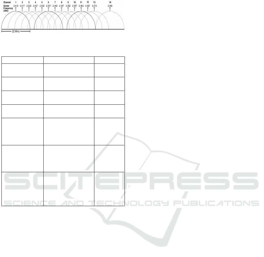
Figure 1: WLAN channels in the 2.4 GHz ISM band.
Table 1: IEEE 802.11 Standards.
Standard Description Status
IEEE 802.11 2.4 GHz, up to 2
Mbps
Finished
1997
IEEE 802.11b 2.4 GHz, DSSS,
up to 11 Mbps
Finished
1999
IEEE 802.11a 5 GHz, OFDM, up
to 54 Mbps
Finished
1999
IEEE 802.11g 2.4 GHz, OFDM,
up to 54 Mbps
Finished
2003
IEEE 802.11n 2.4 GHz and 5
GHz, OFDM,
up to 600 Mbps,
MIMO
Finished
2009
IEEE
802.11ac
5 GHz, MU-
MIMO in down-
link, up to 1300
Mbps
Finished
2013
IEEE
802.11ax
2.4 GHz and 5
GHz, OFDMA,
MU-MIMO for
both downlink
and uplink
Under
devel-
opment,
expected
2019
2 IEEE 802.11 SYSTEMS
IEEE 802.11 systems provide wireless connectivity
for various portable devices. The standards define
both the MAC layer specification and the physical
layer techniques. Table 1 shows IEEE 802.11 stan-
dards, as well as a short description about each and
the year of release. Systems operate in both 2.4 and
5 GHz ISM unlicensed bands. Specifically in the 2.4
GHz band, 83.5 MHz are available, ranging from 2.4
to 2.483 GHz. Fourteen channels –22 MHz each– are
defined in the standard, as shown in Fig. 1. Only three
channels (1, 6 and 11) are not overlapped. Thus, these
channels are used most frequently.
Coordination functions are used to control channel
access. Two functions are defined in the standard: 1)
distributed coordination function (DCF) and 2) point
coordination function (PCF). The DCF, which is most
commonly used, is based on the carrier sense multiple
access/collision avoidance (CSMA/CA) channel ac-
cess method. The device initiates transmission only in
the event that it senses the medium idle for a time pe-
riod (i.e., inter frame space [IFS]). After receiving the
packet, the receiver then sends an acknowledgment to
the transmitter. Given that the transmitter does not re-
ceive an acknowledgment after a certain period, the
transmitter will repeat the transmission up to a certain
maximum number before deferring the transmission,
in such a case, the packet is lost.
The carrier sense is composed of two different
functions: 1) clear channel assessment (CCA) and 2)
network allocation vector (NAV). While the CCA in-
dicates if the medium is busy for the current frame,
the NAV reserves the medium for the transmission
of frames following the most current transmission.
Moreover, CCA is initiated based on two entities:
1) preamble detection (PD) and 2) energy detection
(ED). Preamble detection is used to sense other Wi-
Fi signals by detecting and decoding the preamble of
these signals. If the station detects additional Wi-Fi
signals, the medium should be marked busy through-
out the time required for current frame transmission.
Required time could be established from the Physi-
cal Layer Convergence Procedure header length field.
According to the standard, PD threshold used in Wi-
Fi is set to -82 dBm. ED is used to detect other sys-
tem signals, like Bluetooth, that share the medium
with Wi-Fi or with corrupted Wi-Fi transmissions that
cannot be decoded. In contrast to PD, the necessary
time for the current transmitted frame is unknown.
As such, the device should check the medium for
each time slot, verifying that energy is still present.
The ED threshold used in Wi-Fi equals -62 dBm
in a 20 MHz channel, allowing fairness in sharing
the medium among various 802.11 systems and ad-
ditional non-802.11 systems that share the same unli-
censed frequency band.
The new 802.11ax standard, which is still un-
der development, aims at improving the throughput
in the event of high density OBSSs as stated in the
project authorization request (PAR): “This amend-
ment defines standardized modifications to both the
IEEE 802.11 physical layers (PHY) and the IEEE
802.11 medium access control layer (MAC) that en-
able at least one mode of operation capable of sup-
porting at least four times improvement in the aver-
age throughput per station (measured at the MAC data
service access point) in a dense deployment scenario,
while maintaining or improving the power efficiency
per station.” 802.11ax is the first 802.11 standard to
support multi-user MIMO in both downlink and up-
link. Moreover, the standard improves coexistence
and spatial reuse by differentiating between inter-BSS
and intra-BSS frames using a new field in the frame
called BSS color (Stacey, 2015).
IEEE 802.11 Systems in the Automotive Domain: Challenges and Solutions
43
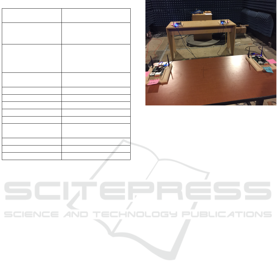
Table 2: Measurement Parameters.
Test cars BMW X6 2016 and Toy-
ota Camry 2003
WLAN boards Mikrotik Router boards
(RB953GS) with R11e-
2HPnD radio cards
Power measurement
hardware
PXIe-1075 chassis
equipped with a PXIe-
5663 vector network
analyzer
AP position Middle console or
driver’s footwell
Station position middle back seat
Standard 802.11n
Channel width 20 MHz
Traffic type UDP
Channel number 11
Channel center fre-
quency
2.62 GHz
Scenario Downlink
Link throughput Maximum achievable
Antenna gain 4 dBi
Nonetheless, this new standard does not consider
mobile Hotspots with speeds higher than 6 mph, due
to the small market share of automotive at the time
when the new group was formed. Regardless, it is ex-
pected that consumer electronic devices will not sup-
port this standard before year 2020, which is already
notably late for the problem addressed in this paper.
3 MEASUREMENT SETUP AND
BASELINE
Measurements are determined using Mikrotik Router
boards (RB953GS) equipped with R11e-2HPnD ra-
dio cards. The Mikrotik boards are fully configurable,
enabling power level and number of RF chains ad-
justments. WLAN connection is established between
two boards, one acting as an access point (AP) and
the other as a station. Their operating system facili-
tated bandwidth tests using both TCP and UDP traf-
fic. The standard 802.11n with 20 MHz channel width
was chosen for all measurements, as it is the most re-
cent standard operating in the 2.4 GHz band. Mea-
surement parameters are summarized in Table 2.
To define ground-truth throughput using the
boards, measurements had to be conducted in ane-
choic chamber. Ground-truth throughput identifies
board performance and acts as a reference for mea-
surements in cars. Initially, two networks working on
the same channel were established. Distance between
Figure 2: Test setup in the chamber.
the AP and the station is 1.5 m, and the distance be-
tween station 1 and station 2 is 1 m. These measures
hold true for APs, as seen in the Fig. 2. Power was
set to 16 dBm for both networks. A 60-second aver-
age was used, and throughput remained stable at near
average. Results are shown in Table 3. The achieved
throughput was 62.8 Mbps for the SISO case for both
networks. For the MIMO case (2x2), 121 Mbps and
116.8 Mbps were the achieved values for networks
1 and 2, respectively. When two networks share the
medium, network throughput for both is quite simi-
lar, and the sum of both throughputs is slightly lower
than the maximum throughout for one pair. The drop
in total throughput –compared to the case when ei-
ther network functions independently– occurs when a
second transmitter joins the channel, which increases
the probability of corrupted transmission. This in turn
leads to a decrease in the throughput. These findings
substantiate work presented in (Rajab et al., 2015).
Throughout the experiment, two cars were parked
parallel to one other, with 1.5 m separation distance
between them, see Fig. 3. To simulate a real life sce-
nario, two cars from different manufacturers –BMW
X6 2016 and Toyota Camry 2003– were used. Ad-
ditionally, two positions of AP –middle console and
driver’s footwell– were considered. The station was
mounted on the middle console of the back seat, as
shown in Figures 4 and 5. In this case, both LOS
and NLOS for propagation inside the car were consid-
ered. A bandwidth test was performed for both SISO
and MIMO (2x2) to establish a baseline for through-
put without interference in the two cars for both posi-
tions of access point (footwell position is not shown
in the figures). Transmission power was tuned from 0
dBm to 16 dBm with 2 dB step size. For middle con-
sole position, in both cars the maximum throughput
was achieved for the SISO case, following the obser-
VEHITS 2017 - 3rd International Conference on Vehicle Technology and Intelligent Transport Systems
44
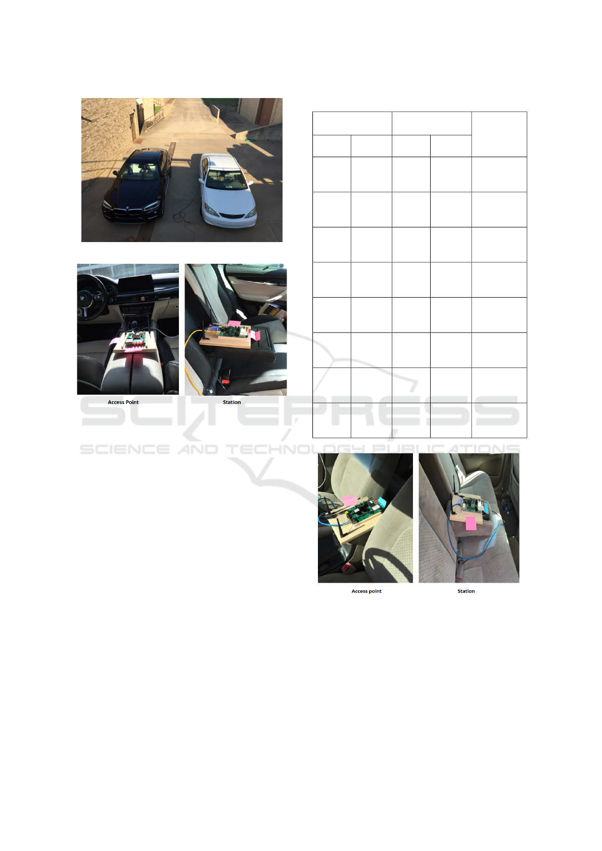
Figure 3: The test setup with the two cars.
Figure 4: Board positions in the BMW, the AP is on middle
console.
vations reported in Table 3. For the MIMO case, a
slight reduction in throughput was achieved for low
power levels. For the footwell position, a slight re-
duction (e.g., 5-10 Mbps) in throughput compared to
middle console position is visible for all power levels,
especially in MIMO case.
A National Instruments (NI) PXIe-1075 chassis
equipped with a PXIe-5663 vector signal analyzer
(VSA) was used to collect power levels. The device
was mounted in several positions inside the cars. Data
were collected using LabView software developed at
the University of Oklahoma (Balid et al., 2016). The
VSA was configured to sweep the entire band (i.e.,
2.4-2.483 GHz) with a resolution bandwidth (e.g., the
fast-Fourier transform (FFT) bin size) of 100 KHz.
Spectrum sweep ran for ten seconds at each mea-
surement point, and then data were post-processed in
MATLAB to calculate probability distribution func-
tion (PDF) of the received power for different cases.
PDFs were used to draw insights from the results.
Notably, results could vary given an alternative
hardware implementation scheme and car model than
the ones used in our setup. However, our results
should be regarded as representative of available com-
mercial devices and cars.
Table 3: Measurement results in anechoic chamber.
Network 1 Network 2
Description
Antenna
Mode
Throughput Antenna
Mode
Throughput
1x1 62.8 N/A N/A
only net-
work 1 is
active
2x2 121 N/A N/A
only net-
work 1 is
active
N/A N/A 1x1 62.8
only net-
work 2 is
active
N/A N/A 2x2 116.8
only net-
work 2 is
active
1x1 30.5 1x1 29.5
both net-
works are
active
2x2 57.5 2x2 55.9
both net-
works are
active
1x1 33.1 2x2 55.9
both net-
works are
active
2x2 60.1 1x1 30.5
both net-
works are
active
Figure 5: Boards position in the Toyota, the AP is on middle
console.
4 MEASUREMENTS RESULTS
In this section, throughput measurements for various
scenarios are presented; results are explained and an-
alyzed using power measurements. In order get rid
of small variations in throughput, sixty seconds av-
erage is used for each power level. Measurements
IEEE 802.11 Systems in the Automotive Domain: Challenges and Solutions
45
−140 −130 −120 −110 −100 −90 −80 −70 −60 −50 −40
0
0.01
0.02
0.03
0.04
0.05
0.06
0.07
0.08
0.09
Power [dBm]
PDF
In Toyota
In BMW
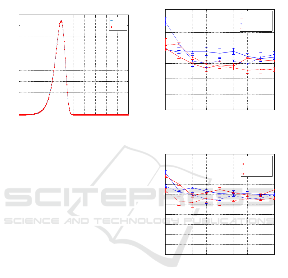
Figure 6: Background noise in both cars.
were repeated four times, which was enough to get
low standard deviation around the mean (< 5Mbps).
Average values, in addition to the standard deviation
around the means, are presented in the figures. Mea-
surements were taken in a location where no active
WLANs or other systems are performing in the same
band. This is verified by spectrum sweep prior to the
test. Fig. 6 shows the PDF of received power in both
cars when all the networks are inactive, noise mean is
approximately
-102 dBm and the VSA is positioned on the middle
console. Fig. 7 and Fig. 8 show the achieved through-
put for a transmission power ranging from 0 dBm to
16 dBm with 2 dB step size in both cars for SISO and
MIMO cases, respectively. Continuous lines repre-
sent middle console position, while dashed lines rep-
resent footwell position.
4.1 AP on Middle Console
In the SISO case and for power levels above 4 dBm,
the sum of throughputs in both cars is slightly lower
than the maximum achieved when only one network
is active. These results are similar to when both net-
works operate in the chamber and demonstrate that
when transmission power is relatively high, through-
put is divided between the cars as a result of sharing
the medium. This means that when multiple cars with
WLANs operating on the same channel are located
near each other (e.g., during a traffic jam) through-
put will be divided between them, resulting in a dra-
matic reduction. Notably, a power level of 16 dBm
is not the maximum-allowed transmission power, as
limits depend on local regulations (e.g., in Germany
19 dBm is the maximum allowed by regulation of-
0 2 4 6 8 10 12 14 16
0
10
20
30
40
50
60
Power [dBm]
Throughput [Mbps]
In Toyota (Middle console)
In Bmw (Middle console)
In Toyota (Footwell)
In BMW (Footwell)
Figure 7: Throughput as a function of power for both AP
positions, SISO in both cars.
0 2 4 6 8 10 12 14 16
0
10
20
30
40
50
60
70
80
90
100
Power [dBm]
Throughput [Mbps]
In Toyota (Middle console)
In BMW (Middle console)
In Toyota (Footwell)
In BMW (Footwell)
Figure 8: Throughput as a function of power for both AP
positions, MIMO in both cars.
fices). For power levels below 4 dBm, throughput
in both cars rises, meaning that both networks can
transmit more often at the same time. When decreas-
ing power, probability of sensing an idle medium in-
creases and leads to an increase in throughput. No-
tably, maximum throughput is not achieved even for a
power level of 0 dBm. This result could be due to of
low SINR values, which leads to erroneous transmis-
sions when both networks transmit simultaneously.
Trends similar to those found in the SISO case are
found in MIMO, see Fig. 8. Nevertheless, for low
power levels, throughput in both cars tends to increase
slightly, primarily due to low power. Probability of
bad link quality for two streams increases; therefore,
VEHITS 2017 - 3rd International Conference on Vehicle Technology and Intelligent Transport Systems
46
more errors are likely to occur.
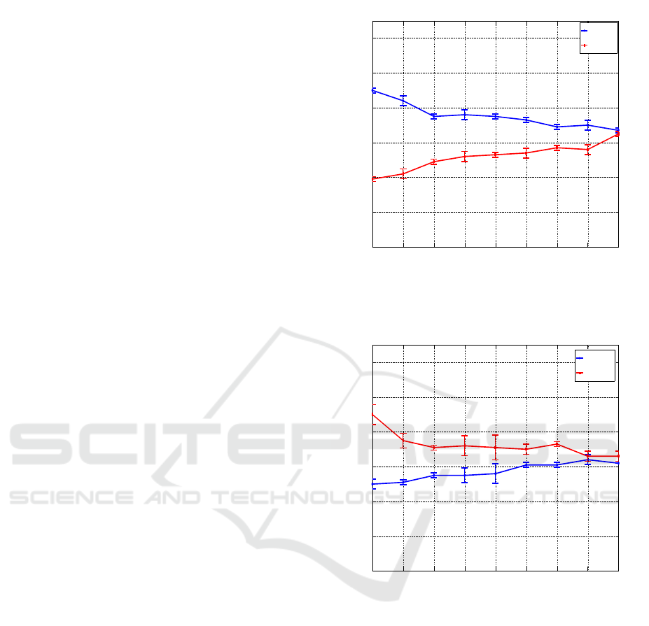
Fig. 9 and Fig. 10 illustrate results when power is
high in one car (i.e., set to 16 dBm) relative to differ-
ent power levels in the second car. The same trend is
visible in both figures. As power decreases through-
put in the car with lower power decreases, as well.
This can be explained by the fact that a car with the
higher power has more chance to transmit by sensing
the idle medium when compared to a car with lower
power. For a power level of 0 dBm, throughput is re-
duced to approximately 20 Mbps in the car with lower
power. This demonstrates unfairness in sharing the
medium when various power levels are used by dif-
ferent car manufacturers. The same behavior is also
observed in the MIMO case. (Figures are not included
in an effort to avoid repeated information.)
Fig. 11 presents results when MIMO is used in
one car (i.e., Toyota) and SISO in another car (i.e.,
BMW), which could be the case in different car mod-
els. The two networks share the medium evenly in a
way similar to that described in previous cases. For
example, at a power level of 16 dBm, the MIMO net-
work achieves 63 Mbps (i.e., almost half the maxi-
mum achieved without interference); the SISO net-
work achieves 30 Mbps (i.e., almost half the maxi-
mum without interference). Increases in throughput
are similar for power levels below 4 dBm.
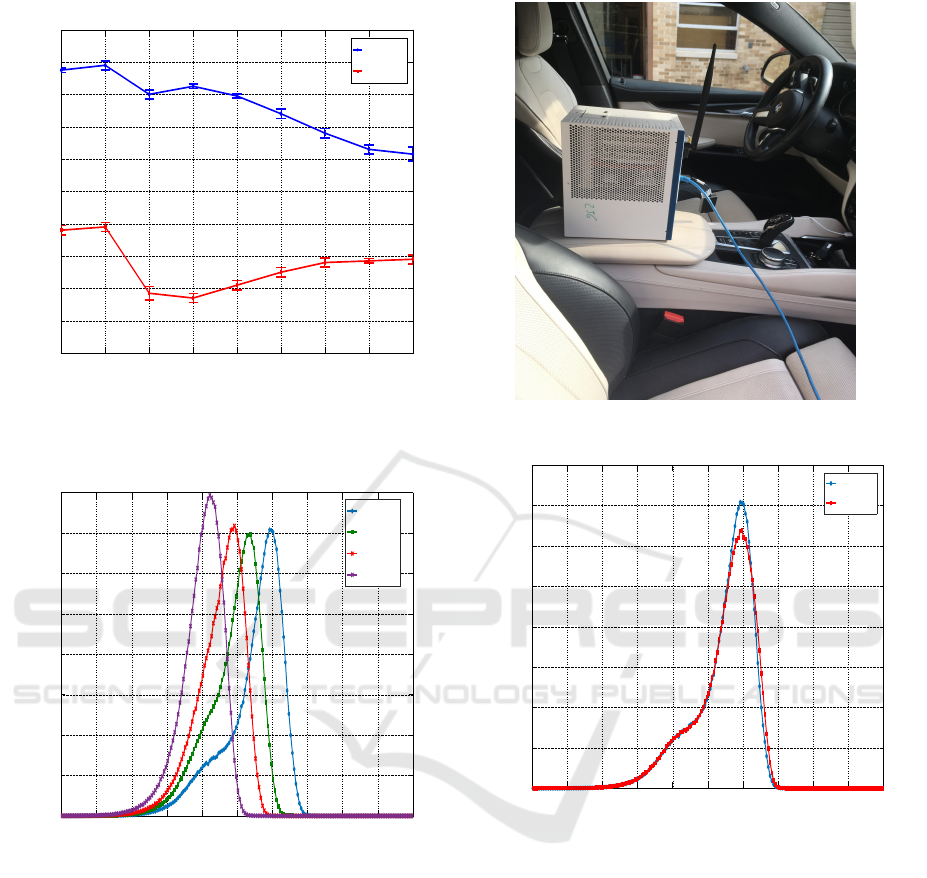
Fig. 12 shows the PDF of received power in the
BMW vehicle when only the network in Toyota is
active with different transmission power. VSA was
positioned on the middle console (similar to AP posi-
tion) as seen in Fig. 13. For a transmission power
of 5 dBm, all packets were received with a power
lower than -82 dBm. This phenomenon explains why
throughput starts to rise in both cars at around (4-5
dBm). Given 0 dBm transmission power, networks
should not sense each other and, therefore, through-
put should rise to high value. However, low SINR
could still lead to erroneous transmissions. As afore-
mentioned, power PDFs are used only for compari-
son. Received power by the boards could be different
due to various RF front-ends. In addition, PD thresh-
old could vary depending on chip manufacturer, even
when a threshold of -82 dBm is defined in the stan-
dard.
Fig. 14 compares the PDF of total power in both
cars when the network in each is active independently
and transmission power is set to 16 dBm. Clearly, the
channel is quite symmetric. Received power in the
BMW is slightly higher than that in Toyota, which
could be the reason for higher throughput in Toyota,
especially in the SISO case.
0 2 4 6 8 10 12 14 16
0
10
20
30
40
50
60
Power in BMW [dBm]
Throughput [Mbps]
In Toyota
In BMW
Figure 9: Throughput as a function of power in BMW,
power in Toyota is fixed to 16 dBm, SISO in both cars.
0 2 4 6 8 10 12 14 16
0
10
20
30
40
50
60
Power in Toyota [dBm]
Throughput [Mbps]
In Toyota
In BMW
Figure 10: Throughput as a function of power in Toyota,
power in BMW is fixed to 16 dBm, SISO in both cars.
4.2 AP in Footwell
In both cars, the access point was positioned in the
driver’s footwell, as shown in Fig. 15. No LOS
between AP and the station led to a minor reduc-
tion of throughput without interference, especially for
MIMO. Fig. 7 illustrates that the trend in throughput
is similar to that of the middle console. However, it
is clear that at the higher power level (e.g., approxi-
mately 6 dBm) throughput starts to rise for both net-
works when compared to middle console. This phe-
nomenon can be interpreted by higher path loss be-
tween the two access points (and stations) in the two
cars. In the first position, the majority of the signals
IEEE 802.11 Systems in the Automotive Domain: Challenges and Solutions
47
0 2 4 6 8 10 12 14 16
0
10
20
30
40
50
60
70
80
90
100
Power [dBm]
Throughput [Mbps]
In Toyota
In BMW
Figure 11: Throughput as a function of power, MIMO in
Toyota, SISO in BMW.
−140 −130 −120 −110 −100 −90 −80 −70 −60 −50 −40
0
0.01
0.02
0.03
0.04
0.05
0.06
0.07
0.08
Power [dBm]
PDF
16 [dBm]
10 [dBm]
5 [dBm]
0 [dBm]
Figure 12: PDF of received power in BMW for four trans-
mission power levels in Toyota, AP and VSA are on middle
console.
are propagating through windows, which have low at-
tenuation at this frequency.
In the second position, there are numerous re-
flections inside the car, so the signals reach the other
car with lower power levels. At power level 0 dBm,
throughput reached 43 Mbps in the BMW and around
57 Mbps in the Toyota. For MIMO (2x2), throughput
in both networks was lower than the middle console
position. This result is related to the absence of LOS
and the multi-path propagation inside the car.
The VSA was positioned separately in the
footwell of both cars to record power values, as seen
Figure 13: VSA position on middle console in BMW.
−140 −130 −120 −110 −100 −90 −80 −70 −60 −50 −40
0
0.01
0.02
0.03
0.04
0.05
0.06
0.07
0.08
Power [dBm]
PDF
In Toyota
In BMW
Figure 14: Received power in both cars for middle console
position, the transmission power is set to 16 dBm.
in Fig. 16. Fig. 17 shows the PDF of total power
for footwell position in both cars. In this position,
the channel is asymmetric and the probability of
receiving higher power level in the BMW is higher
than that of the Toyota. Therein lies the explanation
for higher throughput in the Toyota.
Finally, Fig. 18 demonstrates the PDFs of total
power in the BMW for middle console and footwell
positions. Transmission power for the network in
Toyota in both cases is set to 16 dBm. It is clear
from the figures that regarding the middle console
case, received power from the network in Toyota is
much higher than that of the footwell case. This ex-
plains why throughput rises at a lower power level for
VEHITS 2017 - 3rd International Conference on Vehicle Technology and Intelligent Transport Systems
48
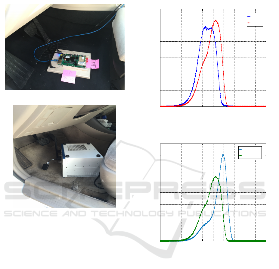
Figure 15: AP position in the driver’s footwell.
Figure 16: VSA position in the driver’s footwell in Toyota.
footwell. Most packets in the middle console case are
received at power levels between -90 and -70 dBm;
footwell position reception is at power levels between
-78 and -100 dBm. It is clear that PDF is much wider
for Footwell due to the richer multi-path environment,
which makes packets arrive with wider power levels.
5 DISCUSSION
Consumer demand is cause for increased interest in
Wi-Fi for both car manufacturers and big technology
companies. In addition relying on Bluetooth for all
intra-car applications is not possible due to low sup-
ported data rates. The main purpose of this work is to
attract interest to this new Wi-Fi usage domain. Con-
sumers have come to expect the same connectivity
services in their cars as they enjoy in their homes and
offices –especially due to the wide use of social media
applications. Improvement in infotainment systems
decreases the use of cellular phones while driving,
hopefully reducing the number of accidents caused by
−140 −130 −120 −110 −100 −90 −80 −70 −60 −50 −40
0
0.01
0.02
0.03
0.04
0.05
0.06
Power [dBm]
PDF
InToyota
In BMW
Figure 17: PDF of received power in both cars for footwell
position, the transmission power is set to 16 dBm.
−140 −130 −120 −110 −100 −90 −80 −70 −60 −50 −40
0
0.01
0.02
0.03
0.04
0.05
0.06
0.07
0.08
Power [dBm]
PDF
Middle console
Footwell
Figure 18: Power received in BMW in two different posi-
tions, the transmission power is 16 dBm in Toyota.
cell phone use.
The automobile Wi-Fi domain is different than
other domains, thus previous research performed in
building environments cannot be easily extended to
the automobile domain. One major difference is the
large number of devices assembled in a restricted
space. For example, some car manufacturers will
have more than three access points in a single car for
different applications. Furthermore necessary coordi-
nation among the applications is not an easy task due
to the complexity of automobile design. Also, the ef-
fect of mobility requires detailed investigation.
In the proposed test setup, two cars were parked
parallel to one other with 1.5 m separation. In order to
study more practical scenarios, similar measurements
IEEE 802.11 Systems in the Automotive Domain: Challenges and Solutions
49

were performed with a 5.2 m distance between the
cars. This separation emulates a free spot between
them. Another investigated scenario was when the
cars are parked in a line with 2.5 m distance. Simi-
lar results were achieved for all tests. Power distribu-
tion shows only a small decrease in power value (e.g.,
approximately 5-10 dB) when comparing tests.
The presented measurements show that given
most vehicles are equipped with WLANs in the near
future, millions of new mobile Hotspots will be trav-
eling our roadways. Unlike networks in building envi-
ronments, these Hotspots will radiate extremely high
energy to surrounding cars. There is concern about
the performance of surrounding Hotspots. One im-
portant example is hospitals, which were studied in
(Al Kalaa et al., 2016). Hospitals utilize sensitive de-
vices with BLE and ZigBee systems that operate in
the 2.4 ISM band. In the event that hundreds of cars
are parked in hospital parking, access points will most
likely affect the wireless systems inside the hospitals.
Two solutions under the standard 802.11n um-
brella are discussed in this paper, namely MIMO and
power control. In (Herbert et al., 2014), a wireless
channel inside the car was studied. Results demon-
strated that the spatial correlation is well defined; thus
deployment of MIMO antenna arrays should be ef-
fective in vehicles. The spatial multiplexing tech-
nique defined in the standard was used in the measure-
ments. Although two data streams were transmitted
simultaneously, a second antenna and RF front-end
is needed, which increase the cost. To date, not all
cellular phones support MIMO, due to limited space
and increased cost. Limiting transmission power is
essential for reducing interference to the surrounding
networks. However, power should not be so low as to
affect link quality inside the car, especially given that
passenger devices can be located anywhere in the car.
It is important to mention that this procedure should
be standard in all cars. Not doing so leads to unfair-
ness in sharing the medium, as measurements demon-
strate above. National and international regulatory of-
fices should take action to this end.
Two positions of AP are discussed, namely mid-
dle console and footwell. Given footwell position, at-
tenuation between the cars is higher. Different AP
positions were discussed in (Blesinger et al., 2012)
and footwell position was proposed to reduce the in-
terference to the surrounding cars. Directive antennas
could be beneficial for this purpose as well. However,
in this study, only the downlink is considered. User
devices can be located anywhere in the car, thus not
controlled by car manufacturers.
One possible solution for this problem is to offload
sensitive application traffic, like video streaming to
the 5 GHz ISM band. Regardless, the 5 GHz band
has some challenges. The car environment is consid-
ered outdoors, and most available channels cannot be
used without radar detection and dynamic frequency
selection. Both of these are difficult to implement
in a moving vehicle. In addition, coexistence with
LTE in the unlicensed band (LTE-U) or license as-
sisted access (LAA) could affect WLAN performance
in the ISM band. Coexistence between WLAN and
LTE-U/LAA remains an ongoing discussion among
the IEEE 802 and 3GPP communities.
6 CONCLUSION AND FUTURE
WORK
Future cars are projected to be equipped with ad-
vanced infotainments systems with options and capa-
bilities similar to those currently available in homes
and offices. Autonomous cars will allow passengers
to efficiently use their in-car time for working or en-
tertaining. Seamless integration of passengers’ con-
sumer electronic devices is a key. 802.11 systems are
the most promising systems to achieve this integra-
tion, providing relatively high data rates in the unli-
censed ISM frequency bands.
This work highlights the coexistence problem in
the automotive domain, focusing on 802.11 systems
used for infotainment applications. Performed mea-
sures show that interference between networks in cars
will be very high compared to building environments.
MIMO techniques could be used to boost the achieved
data rates by spatial multiplexing; in addition MIMO
could also be used to improve robustness by means
of spatial diversity. On the other hand optimal tuning
of transmission power is essential to guarantee good
coverage inside the car and to reduce the interference
with surrounding networks.
The effect of vehicle mobility is a work in
progress, as it is quite important to understand the
difference to other indoor/outdoor scenarios. Coex-
istence of Bluetooth and Wi-Fi in this domain is quite
interesting and could lead to future work. It has yet to
be determined whether or not hands-free calling us-
ing Bluetooth will work when several WLAN signals
with relatively high power level are present. In addi-
tion, analyzing applications used in infotainment sys-
tems is necessary to determine necessary data rates
for each application. Answers offer a better idea of
the severity of throughput reduction due to interfer-
ence.
VEHITS 2017 - 3rd International Conference on Vehicle Technology and Intelligent Transport Systems
50

REFERENCES
Al Kalaa, M. O., Balid, W., Refai, H. H., LaSorte, N. J.,
Seidman, S. J., Bassen, H. I., Silberberg, J. L., and
Witters, D. (2016). Characterizing the 2.4 GHz Spec-
trum in a Hospital Environment: Modeling and Ap-
plicability to Coexistence Testing of Medical Devices.
IEEE Transactions on Electromagnetic Compatibility,
59(1):1–9.
Balid, W., Al Kalaa, M. O., Rajab, S., Tafish, H., and Re-
fai, H. H. (2016). Development of measurement tech-
niques and tools for coexistence testing of wireless
medical devices. In 2016 IEEE Wireless Communi-
cations and Networking Conference Workshops (WC-
NCW), pages 449–454, Doha, Qatar. IEEE.
Blesinger, M., Gehrsitz, T., Fertl, P., Biebl, E., Eerspacher,
J., Klemp, O., and Kellermann, H. (2012). Angle-
Dependent Path Loss Measurements Impacted by Car
Body Attenuation in 2.45 Ghz ISM Band. In 2012
IEEE 75th Vehicular Technology Conference (VTC
Spring), pages 1–5, Yokohama, Japan. IEEE.
Blesinger, M., Kellermann, H., and Biebl, E. (2013). Car
body attenuation impacting angle-dependent path loss
simulations in 2.4 GHz ISM band. In CEM’13 Com-
putational Electromagnetics International Workshop,
pages 38–39, Izmir, Turkey. IEEE.
Heddebaut, M., Deniau, V., and Adouane, K. (2004).
In-Vehicle WLAN Radio-Frequency Communication
Characterization. IEEE Transactions on Intelligent
Transportation Systems, 5(2):114–121.
Herbert, S., Loh, T.-H., Wassell, I., and Rigelsford, J.
(2014). On the Analogy Between Vehicle and
Vehicle-Like Cavities With Reverberation Chambers.
IEEE Transactions on Antennas and Propagation,
62(12):6236–6245.
Kleer (2007). Wireless Digital Audio Quality for Portable
Audio Application, KLEER KLR0000-WP1-1.4,
2007. Retrieved September 02, 2016, from :
http://ww1.microchip.com/downloads/en/DeviceDoc/
Kleer AudioQu- ality.pdf.
Kukolev, P., Chandra, A., Mikul
´
a
ˇ
sek, T., Proke
ˇ
s, A., Ze-
men, T., and Mecklenbr
¨
auker, C. F. (2015). In-vehicle
channel sounding in the 5.8-GHz band. EURASIP
Journal on Wireless Communications and Network-
ing, 2015(1):57.
Lin, J. R., Talty, T., and Tonguz, O. K. (2013). An em-
pirical performance study of Intra-vehicular Wireless
Sensor Networks under WiFi and Bluetooth interfer-
ence. In GLOBECOM - IEEE Global Telecommunica-
tions Conference, pages 581–586, Atlanta, GA. IEEE.
Mourad, A., Heigl, F., and Hoeher, P. A. (2016). Perfor-
mance Evaluation of Concurrent IEEE 802.11 Sys-
tems in the Automotive Domain. In IEELCN, Dubai.
IEEE.
National Safety Council (2013). Annual Esti-
mate of Cell Phone Crashes 2011, 2013.
Retrieved September 02, 2016, from :
http://www.nsc.org/DistractedDrivingDocuments/CPK
/Attributable-Risk-Summary.pdf.
Pfeiffer, F., Napholz, B., Mansour, R., and Biebl, E. M.
(2014). Mutual Influence of Concurrent IEEE 802.11
Networks in an Automotive Environment. In Wireless
Congress 2014, M
¨
unchen.
Rajab, S. A., Balid, W., and Refai, H. H. (2015). Compre-
hensive study of spectrum occupancy for 802.11b/g/n
homogeneous networks. In Conference Record - IEEE
Instrumentation and Measurement Technology Con-
ference, volume 2015-July, pages 1741–1746, Pisa,
Italy. IEEE.
Sbd (2012). 2025 Every Car Connected : Fore-
casting the Growth and Opportunity, 2012.
Retrieved September 02, 2015, from :
http://www.gsma.com/connectedliving/wp-
content/uploads/2012/03/gsma2025everycarconnected.pdf.
Stacey, R. (2015). Specification Framework for
TGax, 2016. Retrieved September 02, 2015, from
: https://mentor.ieee.org/802.11/dcn/15/11-15-0132-
17-00ax-spec-framework.docx.
IEEE 802.11 Systems in the Automotive Domain: Challenges and Solutions
51
