Validation and Control Strategy to Reduce Fuel Consumption
for RE-EV
Wonbin Lee, Wonseok Choi, Hyunjong Ha, Jiho Yoo, Junbeom Wi, Jaewon Jung
and Hyunsoo Kim
School of Mechanical Engineering, Sungkyunkwan University, Suwon, Korea
Keywords: Range Extended Electric Vehicle (RE-EV), Equivalent Fuel Consumption, Optimal Operation Line.
Abstract: In this study, a control strategy of the target RE-EV was analysed using BMW i3 test data from Downloadable
Dynamometer Database (D
3
) at Argonne National Laboratory. In addition, vehicle model was developed
based on AVL Cruise and MATLAB/Simulink and validation of the developed model was carried out. Using
the simulation and test data, a control strategy which operates the engine on the optimal operation line was
proposed to reduce the fuel consumption. The performance of the engine control strategy was evaluated for
the city and highway driving cycle.
1 INTRODUCTION
As the regulations against CO
2
emission has been
strengthened, the demand of eco-vehicle has been
increasing. Electric vehicle (EV) exhausts no
emission, but its relatively short travel distance has
been pointed out as a major drawback (Pavlat, 1993).
Range extended-electric vehicle (RE-EV) is
considered to be a solution to overcome the short
travel distance of EV (Chih-Ming, 2013). RE-EV is a
series type plug-in hybrid vehicle (PHEV) in which
the internal combustion engine and generator are
added in EV (Wu, 2015). In series type, the engine is
used only to charge the battery through the generator
and the motor propels the vehicle using the battery
energy (Tate, 2008). Since the engine is the only
means to charge the battery when RE-EV drives, the
engine turned on/off timing (Pi, 2016), and how to
control the engine are the essential elements to
improve the fuel economy (Min, 2013).
In this study, the engine operation was
investigated for BMW i3 RE-EV using the
experimental data from Downloadable Dynamometer
Database(D
3
) at Argonne National Laboratory
(Anl.gov, 2015). In addition, dynamic model of the
RE-EV was obtained and a performance simulator
was developed based on AVL Cruise and
MATLAB/Simulink. The RE-EV model was
validated by comparing the test results for various
driving cycles. Using the simulation and experimental
results, an engine control algorithm was proposed to
improve the fuel economy.
2 MODELING AND VALIDATION
OF TARGET RE-EV
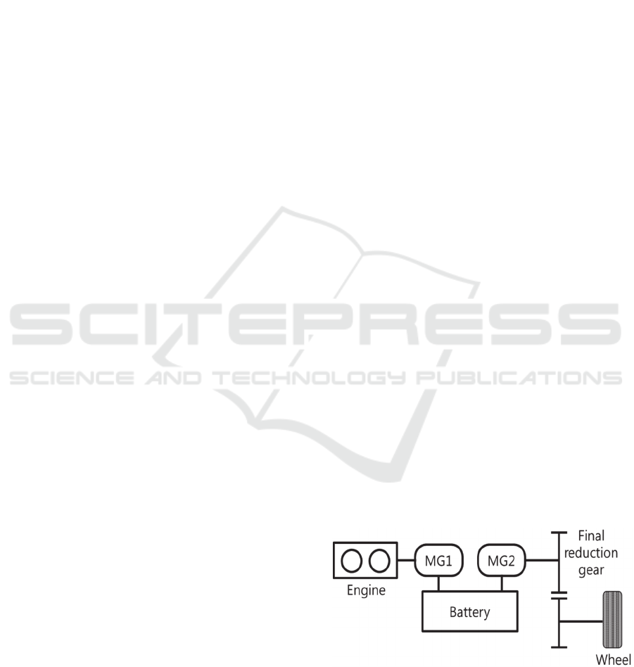
In Figure 1, the target RE-EV, BMW i3 is shown. The
target RE-EV consists of one engine, two
motor/generator, battery and reduction gear.
The target RE-EV utilizes charge depleting (CD)
mode and charge sustaining (CS) mode. In CD mode,
the vehicle is propelled by MG2 using the electric
power. In CS mode, the engine is turned on to operate
MG1 and the electric power of MG1 is charged in the
battery.
Figure 1: Vehicle configuration for RE-EV.
In Table 1, the vehicle specifications are shown.
52
Lee, W., Choi, W., Ha, H., Yoo, J., Wi, J., Jung, J. and Kim, H.
Validation and Control Strategy to Reduce Fuel Consumption for RE-EV.
DOI: 10.5220/0006232900520057
In Proceedings of the 3rd International Conference on Vehicle Technology and Intelligent Transport Systems (VEHITS 2017), pages 52-57
ISBN: 978-989-758-242-4
Copyright © 2017 by SCITEPRESS – Science and Technology Publications, Lda. All rights reserved
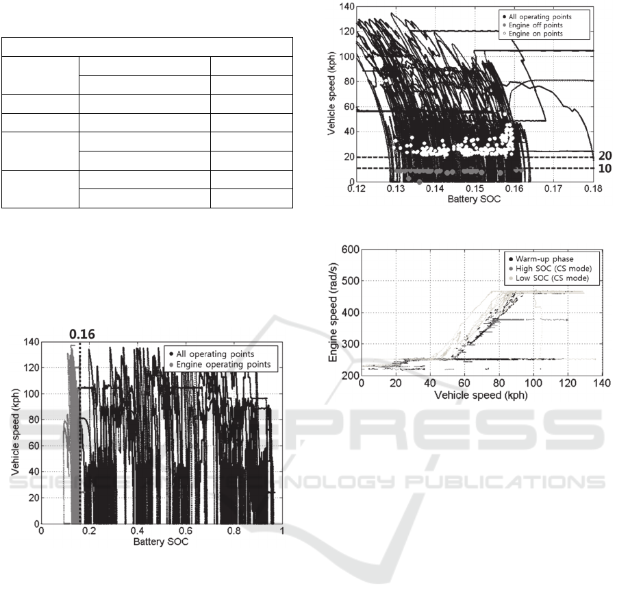
Table 1: Vehicle specifications for RE-EV (Insideevs.com,
2013).
Vehicle specifications
Engine
Max power(kW) 25
Max torque(Nm) 55
MG2 Max power(kW) 125
MG1 Max power(kW) 26.6
Battery
Battery energy (kWh) 22
Capacity(Ah) 60
Vehicle
Mass(kg) 1315
Tire radius(m) 0.33
2.1 Analysis of Test Data
In Figure 2, vehicle operating points and engine
operating points are shown. As shown in Figure 2,
When SOC is below 0.16, CD mode is changed to CS
mode that operates engine.
Figure 2: Vehicle and engine operating points.
In Figure 3, test data of the engine on/off for the
vehicle speed vs. battery SOC are shown (data from
ANL).
In CD mode, the engine is always off since only
the electric energy is used to propel the vehicle. It is
seen from Figure 3 that the engine on/off is
determined by the vehicle speed and battery SOC.
The engine is turned on when the battery SOC drops
below SOC=0.16. In CS mode, the engine is turned
on when the vehicle speed becomes higher than
20kph and turned off when vehicle speed is lower
than 10kph.
Figure 4 shows the engine speed vs. vehicle speed
for various battery SOC in CS mode. It is seen from
Figure 4 that the engine speed increases with the
vehicle speed. When the SOC is low, the engine is
operated at higher speed meanwhile the engine is
Figure 3: Points of engine turned on/off.
Figure 4: Engine speed vs. vehicle speed.
operated at lower speed for high SOC. It is noted that
the engine speed is maintained low when the engine
begins to operate at high SOC. This low engine speed
is considered to warm up the engine and catalyst
converter.
2.2 Modeling and Validation
The target RE-EV was modelled using Cruise. In
Figure 5, Cruise model is shown. Each module in
Figure 5 represents the dynamic model of the RE-EV
component based on mathematical equations
describing its characteristics. For the vehicle control,
MATLAB/Simulink based controller was developed
using test data. Co-simulation was performed using
the Cruise vehicle model and MATLAB/Simulink
controller.
In Figure 6 and Figure 7, simulation results are
compared with the test results for UDDS cycle (city
driving) and HWFET cycle (highway driving). As
shown in Figure 6 and Figure 7, the simulation results
of the vehicle speed, battery SOC, motor torque and
speed, engine speed and the fuel consumption are in
good accordance with the test results, which
demonstrates the validity of the Cruise simulation
model.
Validation and Control Strategy to Reduce Fuel Consumption for RE-EV
53
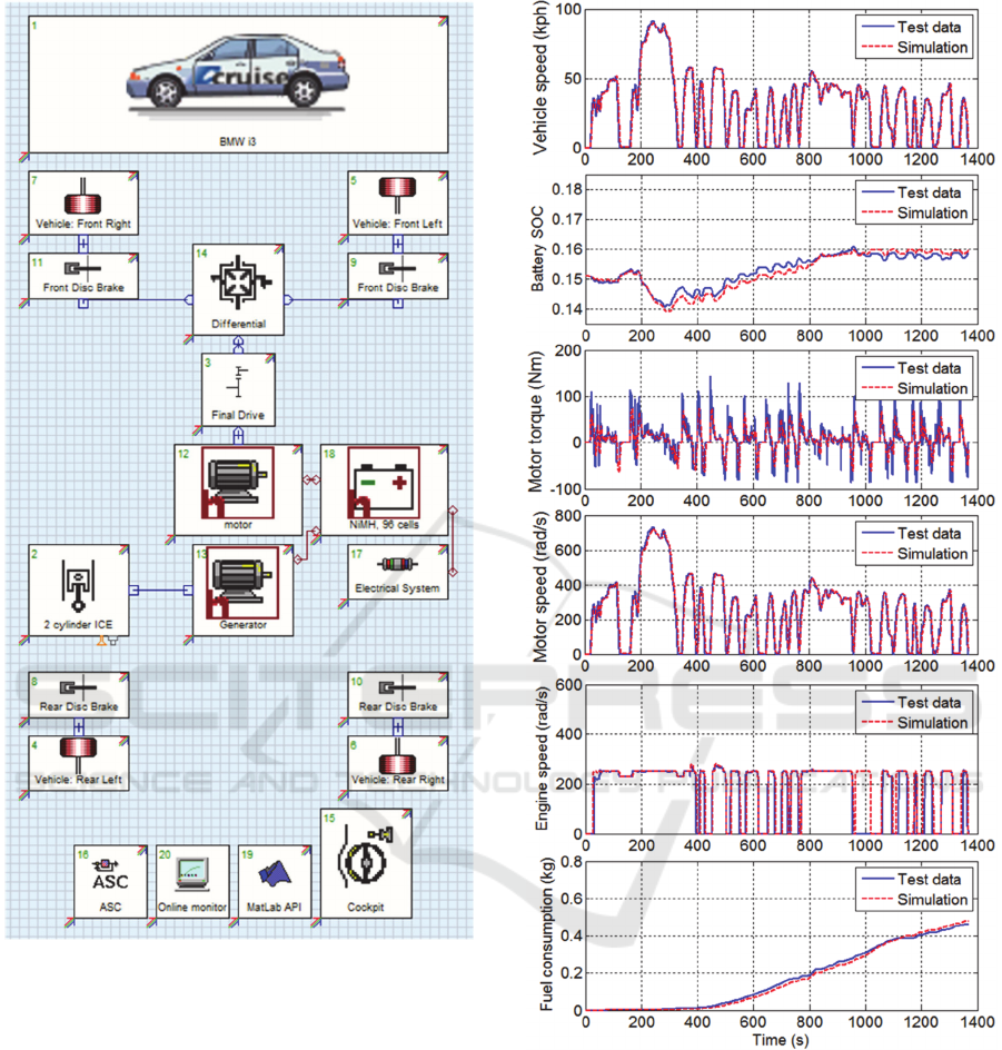
Figure 5: Cruise model of the target RE-EV.
3 CONTROL STRATEGY OF
ENGINE OPTIMAL
OPERATION
3.1 Optimal Operation Line (OOL)
Control
As shown in the test results (Figure 2 ~ Figure 4), the
engine operation of the target RE-EV was performed
according to the vehicle speed and battery SOC
without consideration of the engine thermal
efficiency. Since the target RE-EV is the series type,
Figure 6: CS mode validation results for UDDS cycle.
it is possible to operate the engine independent of the
vehicle speed.
In this study, a control algorithm was proposed to
operate the engine on the optimal operating line
(OOL) that provides the best thermal efficiency. As
shown in Figure 8, the OOL was obtained by
connecting the points which provide the minimum
VEHITS 2017 - 3rd International Conference on Vehicle Technology and Intelligent Transport Systems
54
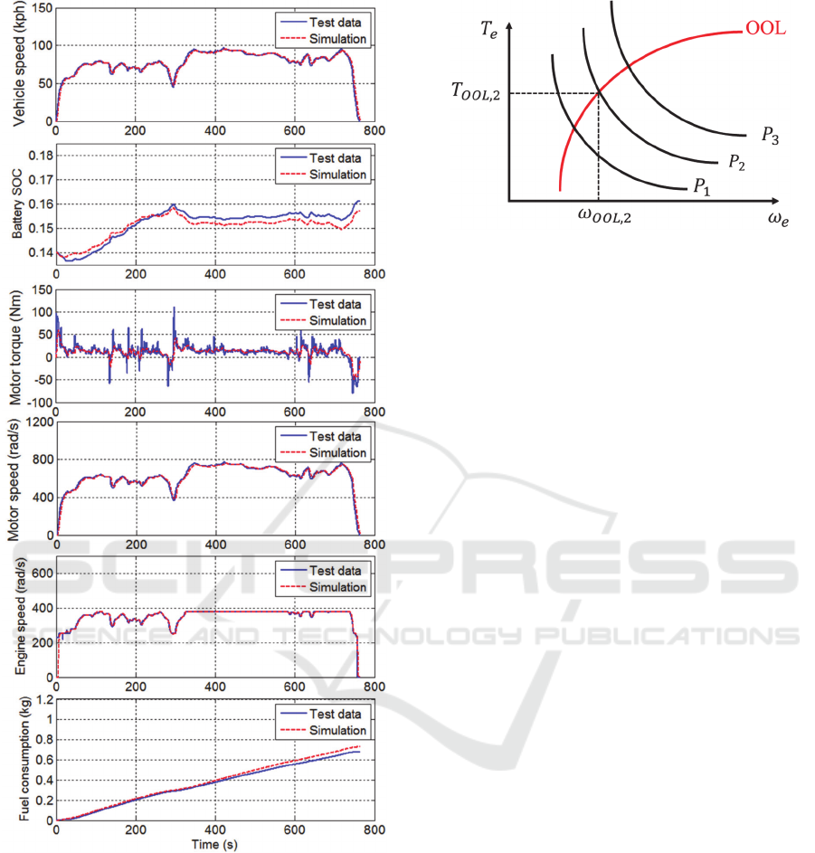
Figure 7: CS mode validation results for HWFET cycle.
fuel consumption for the demanded engine power
(Ma, 2012).
The demanded engine power was obtained by the
motor input power and weight factor considering the
battery SOC balancing in CS mode. The battery
balancing was performed using the weight factor. The
weight factor was designed as a PI controller using
the difference between the target SOC and present
SOC as follows:
Figure 8: Determination of engine operating point in OOL
control.
SOC
(1)
where
SOC
is the weight factor,
,
is the P, I
gain of PI control, respectively.
The demanded engine power was obtained as
_
∙
(2)
where
_
is the engine demand power,
is
the motor input power.
For the demanded engine power, the engine
operating point (torque and speed) is determined from
the OOL. MG1 controls the engine to operate on the
OOL.
The mode change timing and engine on/off timing
were used from the existing control based on the
vehicle speed and battery SOC.
3.2 Results and Discussion
Simulations were carried out to evaluate the
performance of the engine OOL control algorithm. In
simulation, the initial battery SOC and target SOC
were set as 0.18 and 0.16 respectively.
In Figure 9, simulation results are compared for
the OOL control and existing control when the
vehicle drives UDDS cycle. It is seen from Figure 9
that both control follow the driving cycle closely. The
engine speed and torque by the OOL control show
higher value than those of the existing control when
the vehicle speed is high
In Figure 10, simulation results for HWFET cycle
are compared. It is seen that the engine speed
remained around the OOL (250rad/s), which is lower
than that of the existing control, but the engine torque
showed higher value.
Validation and Control Strategy to Reduce Fuel Consumption for RE-EV
55
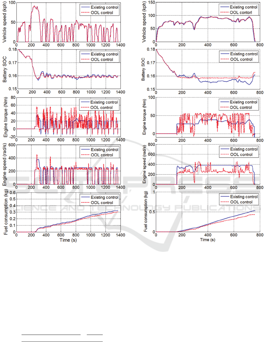
Figure 9: Simulation results for UDDS cycle.
The engine speed by the existing control varied
according to the vehicle speed and battery SOC
(Figure 4). The engine speed by the OOL control
shows relatively lower values than the existing
control. The engine speed and torque were
determined from the OOL using the battery SOC,
motor power and engine power.
To compare the fuel economy, the equivalent fuel
consumption was calculated as follows:
∆
(3)
where D is the distance of cycle,
is the equivalent
gasoline energy of electric energy, is the battery
Figure 10: Simulation results for HWFET cycle.
capacity, ∆
is the fuel consumption,
is the
fuel density.
In Table 2, the equivalent fuel consumptions are
compared for the OOL control and existing control.
It is seen from Table 2 that the equivalent fuel
consumption by the OOL control is lower than that of
the existing control for both UDDS and HWFET
cycle. It is noted that the improvement rate of the
highway cycle (HWFET) is much higher than that of
the city cycle (UDDS). This because the engine
operating points by the OOL control are almost close
to the operation points of the existing control when
the vehicle speed and demanded power are low in the
city driving. However, when the vehicle speed and
demanded power are high in highway driving, the
engine operation by the existing control is performed
VEHITS 2017 - 3rd International Conference on Vehicle Technology and Intelligent Transport Systems
56

Table 2: Comparison of control strategy for UDDS and
HWFET cycle.
Final
SOC
Fuel
consumption
(kg)
Equivalent
fuel
consumption
(l/km)
Im-
prove-
ment
U
D
D
S
Existing
control
0.1599 0.3277 0.0474 -
OOL
control
0.1597 0.3037 0.0449 5.3%
H
W
F
E
T
Existing
control
0.1608 0.5258 0.0500
-
OOL
control
0.1628 0.4303 0.0415 17%
at low torque region when the thermal efficiency is
relatively low meanwhile the engine operation by the
OOL control is carried out at high torque region with
high efficiency.
4 CONCLUSIONS
In this study, the target vehicle is modelled and
validated with test data, and an engine optimal
operation line (OOL) control strategy was proposed
for a range extended electric vehicle (RE-EV) to
reduce the fuel consumption.
The engine control strategy was derived by
analysing the test data from Argonne National
Laboratory. The mode and engine on/off timing are
determined by battery SOC and vehicle speed. The
engine speed is determined by vehicle speed. Using
the engine control strategy, dynamic model of the
target RE-EV which was developed based on Cruise
was validated. It was found that the simulation results
are in good accordance with the test results. Based on
the simulation results, an engine control strategy was
suggested, which operates the engine on the OOL for
the demanded engine power. The demanded was
determined by introducing the weight factor which
balances the battery SOC. From the simulation results,
it was found that the equivalent fuel consumption by
the OOL control is reduced as much as 5.3% for
UDDS and 17% for HWFET compared with that of
the existing control.
REFERENCES
Pavlat, J. and Diller, R. (1993). An Energy Management
System to Improve Electric Vehicle Range and
Performance. IEEE Aerospace and Electronic Systems
Magazine, 8(6), pp. 3-5.
Chih-Ming, C. and Kuang-Shine, Y. (2013). System
Integration and Power Flow Management for the
Engine-Generator Operation of a Range-extended
Electric Vehicle. Electric Vehicle Symposium and
Exhibition (EVS27), 2013 World, pp. 1-10.
Wu, G., Zhang, X. and Dong, Z. (2015). Powertrain
architectures of electrified vehicles: Review,
classification and comparison. Journal of the Franklin
Institute, 352(2), pp. 425-448.
Tate, E., Harpster, M. and Savagian, P. (2008). The
Electrification of the Automobile: From Conventional
Hybrid, to Plug-in Hybrids, to Extended-Range Electric
Vehicles. SAE International Journal of Passenger Cars
- Electronic and Electrical Systems, 1(1), pp. 156-166.
Pi, J., Bak, Y., You, Y., Park, D. and Kim, H. (2016).
Development of Route Information based Driving
Control Algorithm for a Range-extended Electric
Vehicle. International Journal of Automotive
Technology, 17(6), pp. 1101-1111.
Min, H., Ye, D. and Yu, Y. (2013). Optimization of an
Extended-Range Electric Vehicle. Proceedings of the
FISITA 2012 World Automotive Congress, pp. 275-285.
Anl.gov, (2015). Energy Systems / Argonne National
Laboratory. [online] Available at:
https://www.anl.gov/energy-systems [Accessed 10 Sep.
2016]
BMW i3 Range Extender to Offer Up to 87 More Miles,
Decreases Performance | Inside EVs. (2013). [online]
Insideevs.com. Available at:
http://insideevs.com/bmw-i3-range-extender-to-offer-
up-to-87-more-miles-decreases-performance/
[Accessed 10 Sep. 2016].
Ma, C., Kang, J., Choi, W., Song, M., Ji, J. and Kim, H.
(2012). A Comparative Study on the Power
Characteristics and Control Strategies for Plug-in
Hybrid Electric Vehicles. International Journal of
Automotive Technology, 13(3), pp. 505-516.
Validation and Control Strategy to Reduce Fuel Consumption for RE-EV
57
