
Perspectively Correct Construction of Virtual Views
Christian Fuchs and Dietrich Paulus
Active Vision Group, University of Koblenz-Landau, Universit¨atsstraße 1, 56070, Koblenz, Germany
{fuchsc, paulus}@uni-koblenz.de
Keywords:
Virtual Views, Homography Deshadowing, Correct Perspective.
Abstract:
The computation of virtual camera views is a common requirement in the development of computer vision
appliances. We present a method for the perspectively correct computation of configurable virtual cameras
using depth data gained from stereo correspondences. It avoids unnatural warping of 3-D objects as caused by
homography-based approaches. Our method is tested using different stereo datasets.
1 INTRODUCTION
The installation position and orientation of optical
sensors is a crucial issue when planning a computer
vision application. A lot of different requirements
have to be taken into account in order to identify ap-
propriate views of the captured scene for the particu-
lar scenarios. Yet, it is not always possible to mount
a camera in the desired position, e.g. due to geomet-
ric limitations. Therefore, it is not possible to capture
the desired view directly. Common applications are
in top view systems on vehicles of any kind, for ex-
ample, which utilize cameras installed on the vehicle
to compute virtual bird’s views of the surroundings.
Conventional approaches use the images from sin-
gle cameras for the transformation into a virtual cam-
era view. As single camera setups of course do not
provide depth information for the captured scene, the
transformation to a virtual view is a difficult issue.
Most conventional approaches (Section 2) use a flat
world assumption which has several drawbacks in the
resulting virtual camera’s view. Main drawbacks are
the imperfect perspective transformation and the un-
natural warping of 3-D objects.
We address this matter and introduce a method for
creating virtual camera views using depth informa-
tion extracted from stereo images. The goal is to cre-
ate perspectively correct virtual camera views while
avoiding unwanted warping due to violated assump-
tions. Relevant related work is discussed in section 2.
The main drawback of state-of-the-art techniques for
virtual camera view computation is depicted in sec-
tion 3. Sections 4 & 5 introduce the geometric setup
and the mathematic techniques used. Test results are
shown and concluded in sections 6 & 7.
2 RELATED WORK
Several research topics have to be taken into account
when creating virtual camera views. Yet, the follow-
ing paragraphs can only give a short introduction into
the relevant aspects.
2.1 Perspective 2-D Warping
A commonly used approach for the computation of
virtual camera views is the utilization of perspec-
tive transformations as described by Vincent and La-
ganiere (Vincent and Lagani`ere, 2001) and Hartley
and Zisserman (Hartley and Zisserman, 2003): Given
a camera C
1
and a camera C
2
. Camera C
1
captures an
image which shall be converted to the view described
by cameraC
2
. AssumingC
1
looks at a plane on which
all objects on the image are located, the plane in 3-
D space can be described using a minimum of four
image points Q
C
1
=
q
i
∈ IR
2
i ∈ IN
+
, |Q
C
1
| ≥ 4
on the image plane. The image plane of C
1
(re-
spectively C
2
) is thereby interpreted as a projective
plane. Given corresponding image points Q
C
2
=
q
i
∈ IR
2
i ∈ IN
+
with |Q
C
2
| = |Q
C
1
| in image co-
ordinates of C
2
, a transformation from camera C
1
to
camera C
2
can be formulated using a homography
matrix H
C
1
→C
2
∈ IP
2×2
.
Assuming that the cameras to have fixed lenses
and a rigid affine transformation between their poses,
matrix H
C
1
→C
2
can be considered constant.
2.2 Camera Geometry
In order to describe a camera’s imaging properties
properly, camera models for the particular camera
626
Fuchs, C. and Paulus, D.
Perspectively Correct Construction of Virtual Views.
DOI: 10.5220/0006233106260632
In Proceedings of the 6th International Conference on Pattern Recognition Applications and Methods (ICPRAM 2017), pages 626-632
ISBN: 978-989-758-222-6
Copyright
c
2017 by SCITEPRESS – Science and Technology Publications, Lda. All rights reserved

types are needed. Tsai (Tsai, 1987) and Tsai and
Lenz (Lenz and Tsai, 1988) have published funda-
mental work on camera calibration techniques espe-
cially for the pinhole camera model. Their methods
can be used to estimate camera parameters. Based
upon their work, Zhang (Zhang, 2000) has released
an extended approach for camera calibration. Zhang’s
algorithm is widely used in computer vision. Of
course, cameras following another camera model,
need adapted calibration techniques. Geyer and Dani-
ilidis (Geyer and Daniilidis, 2001) published a fun-
damental discussion of the geometry of catadioptric
cameras. Scaramuzza (Scaramuzza, 2008) presents
a solution for proper calibration of omnidirectional
cameras. This method is suitable for catadioptric and
fisheye cameras. The camera parameters estimated
using the methods mentioned are prerequisite for the
connection of camera images to the 3-D world.
2.3 Virtual Camera and Bird’s View
Computation
Various publications address the issue of computing a
virtual camera’s or a bird’s eye view from cameras at
different locations. A common approach for the com-
putation of virtual camera views is the utilization of
homographies (Section 2.1) for the warping process,
which is a reasonable assumption e. g. for vehicles,
as the street can be assumed to be a plane. Consider-
able artifacts are created, e.g. for pedestrians on the
street. Liu, Kin and Chen (Liu et al., 2008) use single
cameras mounted around a car and transform the im-
ages using homography matrices, interpolate and fi-
nally stich the images to a top view image. Addition-
ally, they propose a virtual fisheye view as a bird’s eye
view. Thomas et al. (Thomas et al., 2011) stitch top
view images on a cost-efficient computation system.
Sato et al. (Sato et al., 2013) use fish-eye cameras
and homographies on spatio-temporal data, whereas
Li and Hai (Li and Hai, 2011) focus on the calibra-
tion of a multi-view bird’s eye view. However, the
approaches incorporate heavy distortions for objects
which violate the flat world assumption.
Virtual camera views are discussed in the field of
image-based rendering also. Shum and Kang (Shum
and Kang, 2000) givea survey of different approaches
towards view interpolation. Laveau and Faugeras
(Laveau and Faugeras, 1994) propose view prediction
based on the fundamental matrix using two captured
images. Zinger, Do and De With (Zinger et al., 2010)
discuss a depth based rendering for 3-D-TV applica-
tions based on disparity maps. Vogt et al. (Vogt et al.,
2004) use light-fields to improve image quality in im-
age sequences. However, these publications discuss
the rendering of virtual camera views from camera
poses nearby the original camera’s views, e. g. light
positions shift and/or light rotation.
Up to the best of the author’s knowledge, no ap-
proach towards perspectively correct virtual cameras
with extensively shifted views was published, yet.
2.4 Stereo Vision
Using a multiple camera setup, it is possible to com-
pute depth information from images using multiple
view geometry. Hartley and Zisserman (Hartley and
Zisserman, 2003) summarize the principle behind this
approach. The basic idea behind it is to make use of
known geometric relations between calibrated cam-
eras and to match the image frames taken at a time.
By solving the point correspondence problem, key-
points in corresponding frames can be used together
with the camera calibration data in order to estimate
the 3-D position of an object relative to the cameras.
The precision of the depth estimates is primarily de-
pendent on the cameras, the baseline of the stereo
setup and the matching algorithms.
Concerning the matching of the image content,
two major approaches exist: On the one hand,
the matching of keypoints, computed using algo-
rithms like Scale-Invariant Feature Transform (SIFT)
(Lowe, 2004), Speeded Up Robust Features (SURF)
(Bay et al., 2006) or Oriented FAST and Rotated
BRIEF (ORB) (Rublee et al., 2011), is a possibility.
In general, image features of any kind can be used
as long as an assignment among the image views can
be established. An example for a feature based ap-
proach towards stereo correspondences was presented
by Grimson (Grimson, 1985). Horaud and Skordas
(Horaud and Skordas, 1989) group features in order
to find correspondences.
Approaches using features resp. keypoints for
stereo matching usually result in sparse 3-D data with
high precision matching.
On the other hand, an approach incorporating
block matching constitutes the second main category.
Various algorithms and improvement have been de-
veloped and published so far. Results show dense 3-
D data. The semiglobal matching (SGM) approach by
Hirschm¨uller et al. (Hirschm¨uller, 2008) is based on
mutual information and uses pixel-wise matching. It
shows promising precision properties. The algorithm
has become popular and has already been adapted to
particular scenarios, for example for in-vehicle ap-
plications (Scharwachter et al., 2014; Hermann and
Klette, 2013). An optimized version of the SGM
was presented by Pantilie and Nedevschi (Pantilie and
Nedevschi, 2012). Einecke and Eggert (Einecke and
Perspectively Correct Construction of Virtual Views
627

Eggert, 2015) follow a local correspondenceapproach
in order to significantly reduce execution time while
maintaining correspondence quality. A lot of publi-
cations concerning stereo reconstruction have already
been presented. Therefore, this work does not fo-
cus on this issue. Several datasets for the evaluation
of stereo reconstruction datasets have been published
with an appropriate ground truth.
The KITTI Stereo Benchmark (Geiger et al., 2012)
provides stereo datasets from road scenes for exam-
ple. It is commonly for benchmarks for benchmark-
ing stereo correspondence algorithm. Pfeiffer, Gehrig
and Schneider (Pfeiffer et al., 2013) published the
Ground Truth Stixel Dataset, which contains anno-
tated stereo sequence datasets of road scenes.
The Middlebury Stereo Datasets
1
provide a col-
lection of stereo scenes. We use stereo images from
the newly released 2014 datasets which have been
presented by Scharstein et al. (Scharstein et al., 2014).
The datasets contain high resolution stereo images to-
gether with camera calibration files and ground truth
disparity maps.
3 HOMOGRAPHY SHADOWING
A commonly used approach for the computation of
virtual camera views is the utilization of perspective
transformations as described in section 2.1.
As introduced in section 1, the perspective
transformation using homographies underlies several
drawbacks, because the assumption of a flat world is
mostly violated in real world scenarios. When defin-
ing a virtual camera V, the corresponding point set
has to be computed. A reasonable approach is to use
a calibration pattern with known geometry here. This
way, the points can be calculated for the desired view.
Of course, the resulting homography matrix H
C
1
→V
will rely on the flat world assumption for the defined
plane, which is usually confronted with 3-D objects
visible in the image.
The main effect of the violated flat world assump-
tion is an unnaturally warped image which suffers
from an effect we denote as the Homography Shad-
owing Effect: The shape of the unnaturally warped
object is caused by the violated plane assumption.
The homography transformation incorporates the as-
sumption, that all pixels are on the same plane in 3-D
space. The resulting effect on the image projection is
an effect similar to a shadow effect that occurs when a
point light source is installed at the camera’s position.
The shape of the warped object matches the shape of
1
http://vision.middlebury.edu/stereo/data/
C
1
E
V
Figure 1: Homography Shadowing Effect when using the
yellow plane as the homography plane.
the resulting shadow that would be caused by the light
source at the virtual camera’s position.
The effect is illustrated in Figure 1: Camera C
1
captures the image as depicted on its image plane us-
ing a pinhole camera model. The yellow plane E
is the homography plane for the flat world assump-
tion which is used in the conventional approach. The
viewing rays of C
1
(blue) of course end at the object.
As no depth information is available, the object will
be mapped onto plane E (flat world assumption) when
applying the transformation. The view of virtual cam-
era V is computed using a homography transforma-
tion. Therefore, V will see the object in shape of its
homography shadow (gray). An example for this ef-
fect is shown in Figure 4.c.
4 VIRTUAL CAMERA
GEOMETRY
In order to create virtual camera views, a definition
of the virtual camera is needed. The two approaches
followed are perspective and orthographic projection.
For both projections we assume the z-axis of the
Cartesian coordinate system to be the look direction
of the cameras. However, our method can be easily
extended to other camera projection models.
The perspectiveprojection model follows the prin-
ciples of a pinhole camera. It assumes all rays to pass
through an infinitesimal hole at the camera’s optical
center. A camera’s geometry and lenses form a field
of view
characterized by an intrinsic camera matrix K ∈
IP
2×2
(Hartley and Zisserman, 2003; Lenz and Tsai,
1988; Zhang, 2000; Scaramuzza, 2008):
K =
k
x
0 c
x
0 k
y
c
y
0 0 1
(1)
ICPRAM 2017 - 6th International Conference on Pattern Recognition Applications and Methods
628

with (k
x
, k
y
)
T
∈ IR
2
the camera constants in both x and
y direction of the pixel grid and (c
x
, c
y
)
T
∈ IR
2
the
camera’s principal point. Matrix K is used to describe
the projection of 3-D points to the image plane (2-
D). In case of a virtual camera, the imaging properties
for the cameras have to be defined adequately using a
camera configuration space. Figure 2 shows the geo-
metric properties of a pinhole camera. The definition
contains five parameters, which are u, b, l, r, d ∈ IR. It
is reasonable to assume the camera’s view frustum to
be symmetric (l = r and u = b). This assumption is
incorporated in many camera calibration techniques
as well (e. g. (Tsai, 1987; Lenz and Tsai, 1988)). The
trigonometric relations for the camera opening angles
α (horizontal) and β (vertical) are:
α = 2· atan
r· d
−1
β = 2 · atan
u· d
−1
(2)
In combination with the virtual camera’s target
image resolution (w
V
, h
V
)
T
∈ IN
2
, the imaging pro-
cess of the virtual camera can be described. The as-
pect ratio of a pixel is assumed to be 1 : 1 (quadratic)
in the following paragraphs.
The ratio between w
V
and h
V
is dependent of the
ratio between α and β. Therefore, the configuration
space can be narrowed down to:
conf
p
(V) = (w
V
, h
V
, α)
T
(3)
Using this camera definition, a perspective projec-
tion matrix F
V
∈ IP
2×2
can be formulated with F
V
=
F(conf
p
(V)) as a diagonal matrix:
F
V
=
(tan(0.5α))
−1
0 0
0 w
V
(h
V
tan(0.5α))
−1
0
0 0 1
(4)
This matrix is used for the perspective projection
of the 3-D points into the virtual camera’s image. An
orthographic projection follows a simple idea of pro-
jection. The 3-D points are transformed onto the im-
age plane using orthogonal projection (no perspec-
tive). The principle behind an orthographic projec-
tion is shown in Figure 3. In general, four parameters
are needed for the definition of the camera Figure 2:
u, b, l, r ∈ IR. The same assumptions concerning the
symmetric properties as above can be made. Assum-
d
l
r
u
b
α
β
Figure 2: Parametrization of a pinhole camera.
d
l
r
u
b
Figure 3: Parametrization of an orthographic camera.
ing a target pixel aspect ratio of 1 (square), the camera
is dependent on a scalar factor s ∈ IR. As no perspec-
tive parameter is included in an orthographic projec-
tion, the configuration is:
conf
o
(V) = (w
V
, h
V
, s)
T
(5)
The corresponding matrix for orthographic projection
O
V
∈ IP
2×2
can be defined using O
V
= O(conf
o
(V)):
O
V
=
2(sw
V
)
−1
0 0
0 2(sh
V
)
−1
0
0 0 1
(6)
5 VIRTUAL CAMERA
TRANSFORMATION
The position and orientation of an object in a 3-D
space defined by a Cartesian coordinate system can
be described using a translation and a rotation rela-
tive to the orthonormal bases of the coordinate sys-
tem. The components can be combined to a so called
pose a ∈ IR× H , a = (t, φ), with t ∈ IR
3
, t = (t
x
, t
y
, t
x
)
T
the translation and φ ∈ H, φ = φ
w
+ i·φ
x
+ j·φ
y
+ k· φ
z
the rotation as a unit quaternion. The pose definition
is used to describe a rigid body transform between
two cameras C
1
and C
2
.
Given a vector b ∈ IR
n
, the vector transformed to
homogenous coordinates is represented by
˜
b ∈ IP
n
.
For readability reasons, we use this notation in the
following paragraphs and perform some implicit con-
versions between vectors and their homogenous rep-
resentation.
Now let C
1
be a calibrated camera with dispari-
ties available. These disparities are used for the re-
projection to 3-D space. The goal is to create a per-
spectively correct view of virtual camera V: Given
a set of points P
C
1
=
p
C
1
p
C
1
∈ IR
3
in the coor-
dinate system of C
1
. The transition to the coordi-
nate system of a virtual camera V, whereby pose a
is the transition from C
1
to V, is defined as a function
ϒ
a
:
IR
3
→
IR
3
:
P
V
= ϒ
a
(P
C
1
) ϒ
a
(P) = {υ
a
(p)|∀p ∈ P} (7)
Perspectively Correct Construction of Virtual Views
629

with υ
a
(p) : IR
3
→ IR
3
the transformation of a single
vector from C
1
to V. Let θ : IR
3
× H → IP
3×3
com-
pute the transformation matrix according to pose a.
Function υ
a
(p) is defined as:
υ
a
(p) = θ(a) · ˜p (8)
The projection onto the image plane of camera V
is described by function Γ
V
:
IR
3
→
IR
2
:
Q
V
= Γ
V
(P
V
) Γ
V
(P
V
) = {γ
V
(p)|∀p ∈ P
V
}
(9)
with γ
V
: IR
3
→ IR
2
the projection function for camera
V for a single point p and Q
V
=
q
V
q
V
∈ IR
2
a set
of points on the image plane of V. Let λ
V
describe
the projection matrix for C, which is dependent on
the desired projection:
γ
V
(p) = λ
V
· p (10)
λ
V
= Z
V
·
(
F
V
perspective projection
O
V
orthographic projection
(11)
with Z
V
∈ IP
2×2
the transformation matrix to pixel co-
ordinates with respect to the image resolution of V:
Z
V
=
0.5w
V
0 0.5w
V
0 0.5h
V
0.5h
V
0 0 1
(12)
In case of a perspective projection, K
V
= Z
V
· F
V
holds. The resulting transform from the 3-D points
P
C
1
to the view of V is:
Q
V
= Γ
V
◦ ϒ
a
(P
C
1
) (13)
The steps above perform the transformation from one
camera into the view of a virtual camera. However, it
might be desirable to transform multiple source cam-
eras to one virtual view. Our approach can be ex-
tended to work with multiple source cameras: Given a
set of cameras {C
1
, ..., C
n
} with n∈ IN
+
and the corre-
sponding set of poses {a
1
, ..., a
n
}, the view of virtual
camera V is defined as:
Q
V
= Γ
V
n
[
i=1
ϒ
a
i
(P
C
i
)
!
(14)
Using the transformations described, the view of a
virtual camera can be computed out of one or more
cameras, when depth/disparity data is available.
6 TEST RESULTS
The virtual camera transformation method
proposed was tested using public available
datasets from the Middlebury Stereo Datasets
(a) original image
(Scharstein et al., 2014)
(b) orthographic virtual
view
(c) homography top view
(Hartley and Zisserman,
2003)
(d) orthographic virtual
top view
Figure 4: Result for the dataset “playtable”.
Scharstein et al. (Scharstein et al., 2014). We show
raw results which were computed using the method
we propose. This means that no interpolation for
missing parts of the virtual image is performed, as
we regard this a post-processing matter which would
interfere with the projection quality. In a first test
step, the goal is to just alter the projection model of
the images. An orthographic projection matrix was
configured while the relative pose a was set to the
zero-pose (identity). Figure 4.b shows an example
for the orthographic projection. In the second run, a
virtual view is computed. As the datasets unfortu-
nately do not contain the cameras’ world positions,
pose a had to be manually estimated. Nevertheless,
the projection properties are shown adequately.
The virtual top views use an orthographic projec-
tion and show the transformation to a bird’s view per-
spective. Of course, both perspective and orthogonal
projections were investigated. An example result for
an orthographic top view is giventogether with a clas-
sically computed homography top view in Figure 4.
The configured virtual camera pose is shifted and ro-
tated by 60
◦
which of course leads to a sparse pixel
density in the areas hidden in the original view. In
comparison to the heavily distorted homography top
view, we consider the transformation as proposed in
this publication to be superior. More results computed
using differentdatasets – including shifted and rotated
virtual perspective views – are shown in Figure 5.
7 CONCLUSION
We present a solution for the computation of virtual
camera views using stereo data. Using depth data
ICPRAM 2017 - 6th International Conference on Pattern Recognition Applications and Methods
630
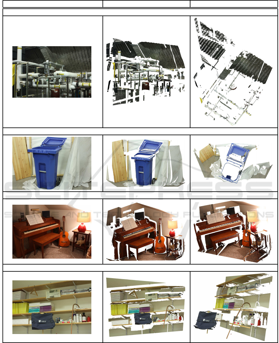
original image (Scharstein et al., 2014) orthographic projection virtual camera view
dataset “pipes” – right: orthographic top view
dataset “recycle” – right: orthographic top view
dataset “piano” – right: perspective projection from different camera pose
dataset “shelves” – right: perspective view from different camera pose
Figure 5: Example transformation results for datasets form the Middlebury Stereo Datasets.
gained from stereo correspondences, it is possible to
create perspectively correct images from other cam-
era poses and configurations. The resulting images
can be used in various appliances. The density of the
pixels in the computed images is dependent of pose
a, so that virtual cameras close to the original camera
Perspectively Correct Construction of Virtual Views
631

will lead to (optical) better results. The incorporation
of adequate interpolation technologies, such as image
inpainting, can improve the quality of the images. As
stated in section 6, this is not the current goal of our
method, but subject of our current research.
REFERENCES
Bay, H., Tuytelaars, T., and Gool, L. V. (2006). SURF :
Speeded Up Robust Features. In European Confer-
ence on Computer Vision, pages 404–417.
Einecke, N. and Eggert, J. (2015). A Multi-Block-Matching
Approach for Stereo. In Intelligent Vehicles Sympo-
sium, pages 585–592.
Geiger, A., Lenz, P., and Urtasun, R. (2012). Are we ready
for Autonomous Driving? The KITTI Vision Bench-
mark Suite. In Computer Vision and Pattern Recogni-
tion, pages 3354–3361.
Geyer, C. and Daniilidis, K. (2001). Catadioptric projective
geometry. International Journal of Computer Vision,
45(3):223–243.
Grimson, W. E. (1985). Computational experiments with a
feature based stereo algorithm. Transactions on Pat-
tern Analysis and Machine Intelligence, 7(1):17–34.
Hartley, R. and Zisserman, A. (2003). Multiple View Geom-
etry in Computer Vision. Cambridge University Press,
New York, NY, USA, 2 edition.
Hermann, S. and Klette, R. (2013). Iterative semi-global
matching for robust driver assistance systems. In
Asian Conference on Computer Vision, pages 465–
478.
Hirschm¨uller, H. (2008). Stereo processing by semiglobal
matching and mutual information. Transactions
on Pattern Analysis and Machine Intelligence,
30(2):328–341.
Horaud, R. and Skordas, T. (1989). Stereo correspondence
through feature grouping and maximal cliques. Trans-
actions on Pattern Analysis and Machine Intelligence,
11(11):1168–1180.
Laveau, S. and Faugeras, O. (1994). 3-D scene representa-
tion as a collection of images. International Confer-
ence on Pattern Recognition, 1.
Lenz, R. K. and Tsai, R. Y. (1988). Techniques for cali-
bration of the scale factor and image center for high
accuracy 3-D machine vision metrology. Transac-
tions on Pattern Analysis and Machine Intelligence,
10(5):713–720.
Li, S. and Hai, Y. (2011). Easy calibration of a blind-spot-
free fisheye camera system using a scene of a parking
space. Transactions on Intelligent Transportation Sys-
tems, 12(1):232–242.
Liu, Y. C., Lin, K. Y., and Chen, Y. S. (2008). Bird’s-eye
view vision system for vehicle surrounding monitor-
ing. LNCS, 4931:207–218.
Lowe, D. G. (2004). Distinctive image features from scale-
invariant keypoints. International Journal of Com-
puter Vision, 60(2):91–110.
Pantilie, C. D. and Nedevschi, S. (2012). SORT-SGM: Sub-
pixel Optimized Real-Time Semiglobal Matching for
Intelligent Vehicles. Transactions on Vehicular Tech-
nology, 61(3):1032–1042.
Pfeiffer, D., Gehrig, S., and Schneider, N. (2013). Exploit-
ing the power of stereo confidences. Computer Vision
and Pattern Recognition, pages 297–304.
Rublee, E., Rabaud, V., Konolige, K., and Bradski, G.
(2011). ORB - an efficient alternative to SIFT or
SURF. In International Conference on Computer Vi-
sion, pages 2564–2571.
Sato, T., Moro, A., Sugahara, A., Tasaki, T., Yamashita,
A., and Asama, H. (2013). Spatio-temporal bird’s-eye
view images using multiple fish-eye cameras. Interna-
tional Symposium on System Integration, pages 753–
758.
Scaramuzza, D. (2008). Ominidirectional vision: from cal-
ibration to robot estimation. PhD thesis, Citeseer.
Scharstein, D., Hirschm¨uller, H., Kitajima, Y., Krath-
wohl, G., Neˇsi´c, N., Wang, X., and Westling,
P. (2014). High-Resolution Stereo Datasets with
Subpixel-Accurate Ground Truth. German Confer-
ence on Pattern Recognition, 1(2):31–42.
Scharwachter, T., Schuler, M., and Franke, U. (2014). Vi-
sual guard rail detection for advanced highway assis-
tance systems. Intelligent Vehicles Symposium, pages
900–905.
Shum, H.-Y. and Kang, S. B. (2000). A review of image-
based rendering techniques. Proc. SPIE Visual Com-
munications and Image Processing, pages 2–13.
Thomas, B., Chithambaran, R., Picard, Y., and Cougnard,
C. (2011). Development of a cost effective bird’s eye
view parking assistance system. Recent Advances in
Intelligent Computational Systems, pages 461–466.
Tsai, R. Y. (1987). A Versatile Camera Calibration Tech-
nique for High-Accuracy 3D Machine Vision Metrol-
ogy Using Off-the-Shelf TV Cameras and Lenses.
Journal on Robotics and Automation, 3(4):323–344.
Vincent, E. and Lagani`ere, R. (2001). Detecting planar ho-
mographies in an image pair. International Sympo-
sium on Image and Signal Processing and Analysis,
0(2):182–187.
Vogt, F., Kr¨uger, S., Schmidt, J., Paulus, D., Niemann, H.,
Hohenberger, W., and Schick, C. H. (2004). Light
fields for minimal invasive surgery using an endo-
scope positioning robot. Methods of information in
medicine, 43(4):403–408.
Zhang, Z. (2000). A flexible new technique for camera cal-
ibration. Transactions on Pattern Analysis and Ma-
chine Intelligence, 22(11):1330–1334.
Zinger, S., Do, L., and De With, P. H. N. (2010). Free-
viewpoint depth image based rendering. Journal of Vi-
sual Communication and Image Representation, 21(5-
6):533–541.
ICPRAM 2017 - 6th International Conference on Pattern Recognition Applications and Methods
632
