Real-time Vision-based UAV Navigation in Fruit Orchards
Dries Hulens, Maarten Vandersteegen and Toon Goedem´e
EAVISE, KU Leuven, Jan de Nayerlaan 5, Sint-Katelijne-Waver, Belgium
{dries.hulens, maarten.vandersteegen, toon.goedeme}@kuleuven.be
Keywords:
Unmanned Aerial Vehicle, Agriculture, Orchard, Vision-based Navigation.
Abstract:
Unmanned Aerial Vehicles (UAV) enable numerous agricultural applications such as terrain mapping, monitor
crop growth, detecting areas with diseases and so on. For these applications a UAV flies above the terrain and
has a global view of the plants. When the individual fruits or plants have to be examined, an oblique view
is better, e.g. via an inspection-camera mounted on expensive all-terrain wheeled robots that drive through
the orchard. However, in this paper we aim to autonomously navigate through the orchard with a low-cost
UAV and cheap sensors (e.g. a webcam). Evidently, this is challenging since every orchard or even every
corridor looks different. For this we developed a vision-based system that detects the center and end of the
corridor to autonomously navigate the UAV towards the end of the orchard without colliding with the trees.
Furthermore extensive experiments were performed to prove that our algorithm is able to navigate through the
orchard with high accuracy and in real-time, even on embedded hardware. A connection with a ground station
is thus unnecessary which makes the UAV fully autonomous.
1 INTRODUCTION
Nowadays drones are used in many applications such
as search and rescue, inspection of buildings, per-
forming 3D reconstructions and so. A fairly new ap-
plication is fruit growth estimation in orchards. By
regularly inspecting the fruit orchard, diseases can
be detected in an early state. This avoids the need
to fully spray the entire orchard and only the in-
fected trees can be treated. Obviously this is a time-
consuming task for the farmer and therefore not fea-
sible. In this paper we propose a vision-based tech-
nique to steer a UAV (Unmanned Aerial Vehicle) au-
tonomously through an orchard. Techniques to count
fruit in an orchard (Puttemans et al., 2016) or to de-
tect diseases on fruit are already wildly discussed
in literature (Garcia-Ruiz et al., 2013; Spadaro and
Gullino, 2004) and therefore we focus on the naviga-
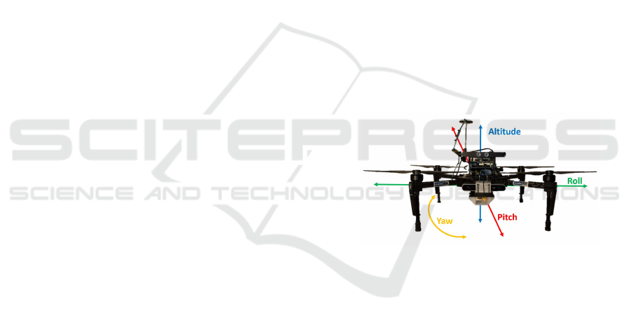
tion part. A UAV has four DOF (Degrees Of Free-
dom) as shown in figure 1. The pitch causes the UAV
to go forward or backward, the roll is used to go to the
left or right, the yaw rotates the UAV around its verti-
cal axis and the trust is used to control the altitude.
To fly autonomously through an orchard the UAV
is equipped with a frontal looking camera and on-
board processing. The camera captures images of the
corridor and passes these to the on-board processing
board which processes the images and controls the
Figure 1: Matrice M100 from DJI with a Logitech C310
webcam and Barebone Brix mini computer.
UAV accordingly. To fly through the orchard without
colliding with the trees the UAV should always fly in
the middle of two tree lines, facing the end of the cor-
ridor. Accordingly, the middle and end of the corridor
is detected by our algorithm which is used to control
the roll (to stay in the center of the corridor) and the
yaw (to face the UAV to the end of the corridor).
When the end of the corridor is reached, one of the
possibilities is to use GPS to fly to the next corridor,
but this is not covered in this paper. The UAV that
we are using is a Matrice M100 (see figure 1) from
DJI equipped with a Brix mini computer containing
an Intel i7 processor and 8GB RAM. The flight con-
troller that we use is the N1 also from DJI. We also ran
our algorithm on two smaller Odroid processing plat-
forms containing a Samsung Exynos4412 and a Sam-
sung Exynos5422processor with 2GB of RAM which
only weigh approximately 52 and 70 grams. These
Hulens D., Vandersteegen M. and GoedemÃl’ T.
Real-time Vision-based UAV Navigation in Fruit Orchards.
DOI: 10.5220/0006242906170622
In Proceedings of the 12th International Joint Conference on Computer Vision, Imaging and Computer Graphics Theory and Applications (VISIGRAPP 2017), pages 617-622
ISBN: 978-989-758-225-7
Copyright
c
2017 by SCITEPRESS – Science and Technology Publications, Lda. All rights reserved
617
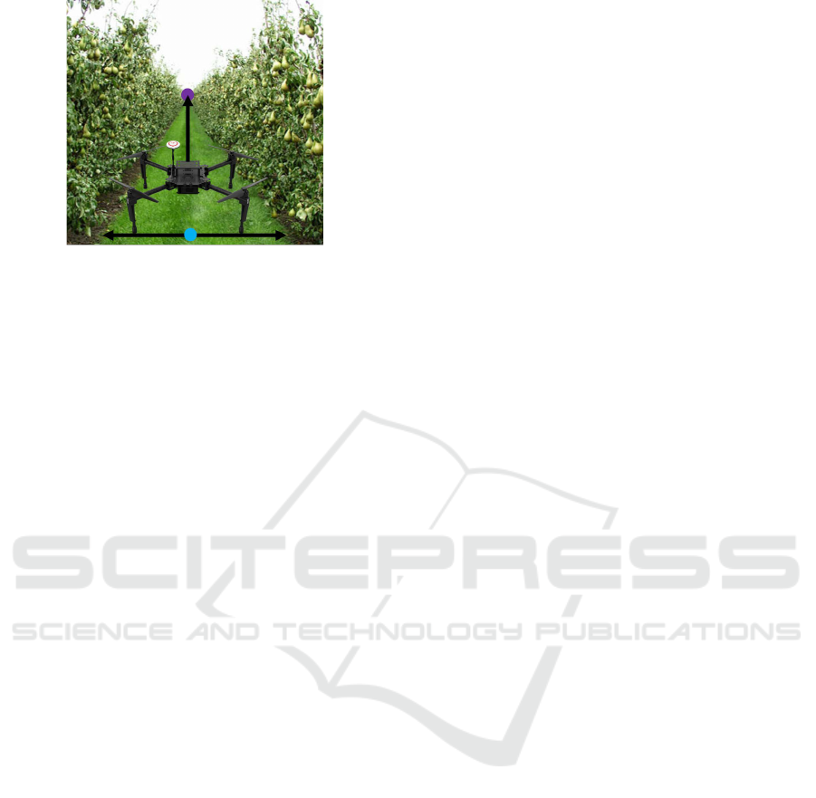
Figure 2: An example of an orchard. Blue point is the CP
of corridor and purple point is the VP of the corridor.
platforms can be mounted on even smaller UAVs.
The remainder of this paper is structured as fol-
lows; in Section 2 we relate our method with the cur-
rent literature. In Section 3 we explain how we detect
the vanishing point and center point of the corridor to
correct the yaw and roll of the UAV during flight. In
Section 4 our results are discussed and in Section 5
conclusions are drawn and future work is discussed.
2 RELATED WORK
As discussed in (Pajares, 2015) UAVs are used in a
lot of applications and carrying different sensors to
extract information out of their environment.
UAVs are more and more used to fly over fields in
open space for constructing a (3D)map for precision
agriculture as in (Zarco-Tejada et al., 2014) where
they monitor plant growth. Also diseases can be de-
tected in an early state by a UAV flying over the ter-
rain as in (Garcia-Ruiz et al., 2013) where a hyper-
spectral camera is mounted on the UAV to find ab-
normalities in citrus trees. In (Colomina and Molina,
2014) an overviewis given of different photogramme-
try and remote sensing techniques.
In (Puttemans et al., 2016) software was devel-
oped to detect and count fruit from images taken
from a camera mounted on a wheeled robot for early
harvest estimation. When a more accurate view of
the fruit is needed generally wheeled robots are used
that can drive trough the orchard like in (Christiansen
et al., 2011; Barawid et al., 2007; Andersen et al.,
2010; Hiremath et al., 2014) where they use a LI-
DAR combined with other sensors like GPS to drive
through the orchard. Or in (Rovira-M´as et al., 2008)
where stereo vision is used to make a 3D map of the
orchard with a wheeled robot. The disadvantage of
these robots is that they are all carrying a heavy and
expensive laser scanner. In (Xue et al., 2012) vision-
based techniques are used to find the path between the
trees. Here a simple color segmentation is used to dis-
tinguish the path from the corn plants. Of course, still
a very expensivewheeled robot is needed that requires
frequent maintenance.
Navigating through an orchard with a UAV instead
of a wheeled vehicle has multiple advantages. The
slope and condition of the path is not that important
as when using a wheeled robot. Furthermore, a UAV
flies much faster and the cost of a UAV and its main-
tenance is much lower than with a wheeled robot.
Initial experiments with UAVs flying through an
orchard were already performed by (Verbeke et al.,
2014) where they designed a UAV-frame specifically
to fly in fruit orchards, which can be equipped with a
small computer and cameras. In (Stefas et al., 2016),
they experimented with a monocular and binocular
camera to retrieve the path between the tree rows. Un-
fortunately, their algorithm is based on a traffic lane
detection algorithm and results in a poor classification
of the tree rows.
We developed a new approach to navigate through
an orchard using a cheap webcam and on-board pro-
cessing. Our approach has a high accuracy both in
finding the center and the end of the corridor. No ex-
pensive laser scanner or robot is needed and our sys-
tem can be used in multiple types of orchards.
3 APPROACH
When a human is walking through an orchard he fol-
lows the path to avoid collisions with the trees. Two
actions are taking place; 1. The human tries to stay in
the middle of the path, 2. The human looks to the end
of the corridor to walk in a straight line. The same is
true for a UAV, the roll should be controlled to stay
in the center of the path and the yaw to keep the nose
of the UAV pointing towards the end of the corridor.
Evidently, the pitch is steered at a fixed speed to go
forward and the altitude is maintained stable.
To control these two DOF, the roll and yaw, we de-
veloped an algorithm that estimates the center of the
corridor (CP, center point) and the end of the corri-
dor (VP, vanishing point). The algorithm is designed
to estimate these two points in a computational low-
cost-manner so they are able to run in real-time on
embedded hardware, mounted on the UAV. Figure 3
shows the overall system where the CP and the VP
are found. In section 3.1 we first show how we esti-
mate the CP and in section 3.2 we explain how the VP
is found.
VISAPP 2017 - International Conference on Computer Vision Theory and Applications
618
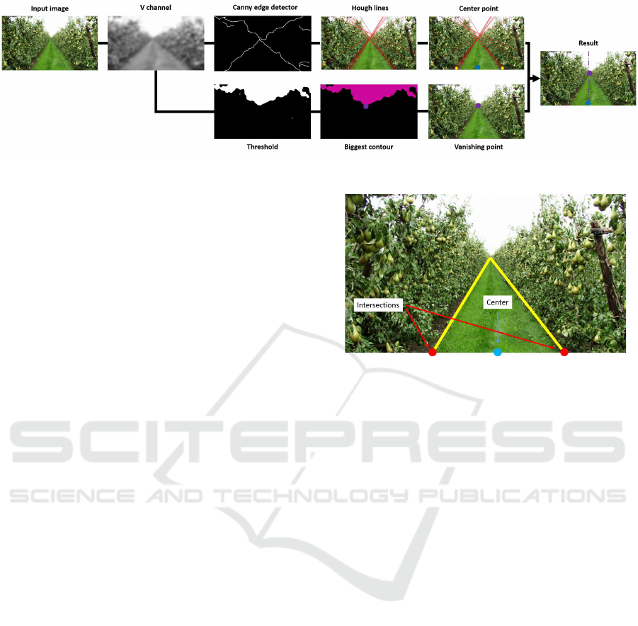
Figure 3: Overall system. Upper part: center point detection. Lower part: vanishing point detection.
3.1 Center Point Estimation
As seen in figure 4 the center of the corridor (blue)
is found between the intersections (red) of the bound-
aries of the grass path (yellow) and the horizontal axis
on the bottom of the input image. At first sight the
color transition between the path and trees could be
used to detect these intersections but experiments in
multiple types of orchards show that the color of the
path and trees differs a lot. Therefore we used the
difference in brightness between trees and path which
will always be visible regardless the type of orchard.
The brightness is found by converting the input image
from RGB to HSV. The V channel (value) represents
the brightness of the image as seen in figure 3 where
the grass, trees and sky are easily distinguishable.
Next, a Canny edge detector is used to detect the
changes in brightness (borders between trees and path
and trees and sky). On this result a Hough line de-
tector is used to detect straight lines which results in
figure 3 (Hough lines).
Finally the intersections between the Hough lines
and the bottom horizontal axis are calculated and an
average is found for the left and right intersection as
in figure 3 (Center point - yellow dots). The center
point is now found in between the two intersections.
As seen, Hough lines are also found between the trees
and sky because of the difference in brightness. How-
ever they do not affect the result since they don’t in-
tersect with the bottom horizontal axis.
To correct the position of the UAV to the center of
the corridor, the error between the center of the image
and the center of the corridor is used.
3.2 Vanishing Point Detection
To fly through an orchard the nose of the UAV has to
point towards the end of the corridor. Therefore the
yaw of the UAV should be automatically controlled
to point that way. We could use the intersections of
the previouslyfound Hough lines which intersect with
each other more or less at the end of the corridor to
Figure 4: Yellow: Borders of the grass path. Red: Inter-
section of the borders with the horizontal axis of the frame.
Blue: The center of the intersections and also the center of
the path called the center point (CP).
estimate the VP. However,in cases where a lot of lines
are found in the trees (which have little effect on the
CP) the VP is not estimated correctly as illustrated
in figure 5. Here the VP is the mean of all Hough
line intersections and is indicated in blue where the
real VP is indicated in green. To estimate the VP in
a more accurate way we make use of the fact that the
sky is always brighter than the trees and grass.
We dynamically threshold the V channel of the in-
put image (see figure 3) to separate the sky from the
rest of the image. Due to the light shining through
the leafs some bright spots occur besides the sky. To
neglect these bright spots a biggest contour finding al-
gorithm is used to only keep the sky in the image as
in figure 3. Due to the shape of a corridor, the sky
always looks like a triangle pointing down where the
tip of the triangle (lowest point of the contour) repre-
sents the end of the corridor and thereby corresponds
to the VP. Here the error between the VP and the cen-
ter of the frame is used to correct the yaw of the UAV.
The assumption of the triangular shape of the sky is
no longer true at the end of the corridor, which is not
an issue in our case since here GPS is used to navigate
to the beginning of the next corridor.
To ensure a smooth flight the position of the VP
and the CP are filtered with a Kalman filter (Kalman,
1960). When a frame occurs where the VP or the CP
cannot be found, the Kalman filters’ prediction is used
Real-time Vision-based UAV Navigation in Fruit Orchards
619
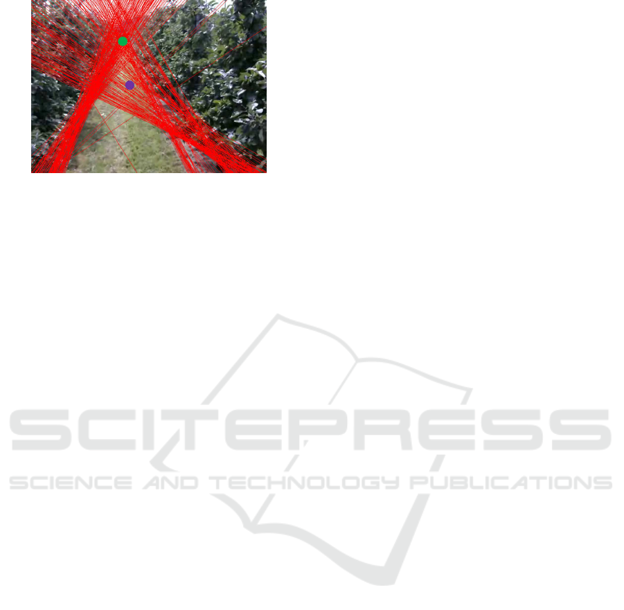
Figure 5: Red: Lines found by Hough Lines algorithm. Pur-
ple: Mean of all intersections of the Hough lines. Green:
Real vanishing point (VP).
instead.
There is no need for calibrating the camera w.r.t.
the UAV before each flight, although the camera
should be mounted looking as straight ahead as possi-
ble. Small misalignments of the camera can cause the
UAV to not position itself exactly in the center of the
corridor or not looking perfectly to the VP.
4 EXPERIMENTS AND RESULTS
We performed extensive experiments on 10 different
video sequences captured by a UAV flying (manually)
through an orchard, adding up to a dataset of 6026
frames in total. In each video sequence 60 frames
were randomly selected, yielding 600 frames to eval-
uate. In each frame the CP and the VP was annotated
and compared with the results of our algorithm. Fig-
ure 6 shows qualitative results of the output of our
algorithm.
4.1 Center Point Experiments
In our experimentswe measured the error between the
annotated CP and the estimated CP (without Kalman
filtering). This error is measured in pixels on the hori-
zontal axis. The maximum allowed error that the UAV
can fly to the left or right before colliding with the
trees is the half of the width of the path (0.75m). The
width of the path in the image (expressed in pixels)
is changing according to the altitude of the UAV. The
lower the UAV flies the larger the width of the path
is in the image. Consequently we took the worst case
scenario where the UAV flies at 2m height and the
path is approximately 200 pixels wide. This means
that the maximal error is 100 pixels (or 0.75m) in both
directions. In figure 7 the cumulative error is plotted
with respect to the percentage of samples (frames).
As seen the average error is 0.17m (green dot) and
almost 60% of the samples has a lower error. The
average error is considerable smaller than the maxi-
mal error of 0.75m which means that our algorithms
succeeds successfully in finding the center of the cor-
ridor.
4.2 Vanishing Point Experiments
We conducted the same experiment to evaluate the
correctness of the estimated vanishing point. The dif-
ference here is that it is difficult to state a maximum
allowed error. When the error is more than 320 pixels
(half of the frame width) the VP is no longer visible
and retrievable. The Field of view of the camera is
60°which corresponds to 640 pixels yielding a maxi-
mal yaw error of 30°.
In figure 8 the cumulative error is plotted w.r.t. the
amount of frames. As seen the average error (green
dot) is only 0.75°and almost 70% of the samples have
an even lower error. Without correcting for this error ,
the maximal distance that the UAV still can fly, is cal-
culated as seen in figure 9. The maximal distance the
UAV can fly before it collides with the trees is 57.7m.
Normally this is impossible since in every frame a
new vanishing point is estimated and corrected.
This is an excellentresult and provesthat our algo-
rithm is capable of detecting the vanishing point with
very high accuracy.
4.3 Speed Test on Embedded Hardware
We developed a vision-based algorithm to detect the
end and center of a corridor in a fruit orchard. This
algorithm yields a frame-rate of more than 30fps on
a Brix mini computer (Intel i7, 8GB RAM) mounted
on our UAV. This UAV is preprogrammed to fly at
a maximal speed of 1m/s through the orchard. This
means that every 3.3cm the VP and the CP is de-
tected and the UAV its yaw angle and roll is cor-
rected. Evidentlywe want the algorithm to run in real-
time on even smaller embedded computers that can be
mounted on small UAVs. We did experiments with
two such embedded computers; an Odroid U3 (Sam-
sung Exynos4412, 2GB RAM) and a Odroid XU3
(Samsung Exynos 5422, 2GB RAM) computer. On
the Odroid U3 the algorithm runs at 8fps and on the
Odroid XU3 at 12fps. This implies that every 12.5cm
(U3) and 8.3cm (XU3) the course of the UAV will be
corrected. The speed of the algorithm can be further
increased (for faster flying UAVs) by using the predic-
tion of the Kalman filter between detections results.
VISAPP 2017 - International Conference on Computer Vision Theory and Applications
620
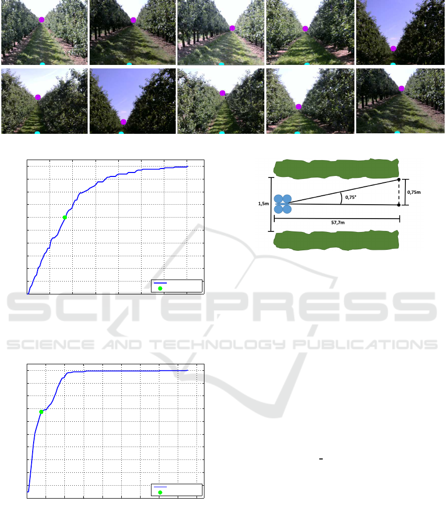
Figure 6: Qualitative results of the output of our algorithm. Blue: the CP, Purple: the VP.
0 10 20 30 40 50 60 70
0
10
20
30
40
50
60
70
80
90
100
% samples
Error (centimeter)
Cumulative error
Average error
Figure 7: Center point cumulative error. For each error
value the percentage of all frames with equal or lower error
rate is given. The average error is displayed with a green
dot. The maximal allowed error is 0.75m.
0 1 2 3 4 5 6 7 8 9
0
10
20
30
40
50
60
70
80
90
100
% samples
Error (degrees)
Cumulative error
Average error
Figure 8: Vanishing point cumulative error. For each error
value the percentage of all frames with equal or lower error
rate is given. The average error is displayed with a green
dot. The maximal allowed error is 30°.
5 CONCLUSIONS AND FUTURE
WORK
We developed a lightweight (in terms of processing
power) vision-based algorithm to navigate a UAV au-
Figure 9: When the average yaw error is 0.75°and the half
of the width of the path is 0.75m, the maximum distance the
UAV can fly, before colliding with trees, is 57.7m. This is
in worst case when in every frame the same average error
should be present.
tonomously through a fruit orchard. The center of
the corridor is successfully estimated to position the
UAV between the trees as well as the vanishing point
to align the nose of the UAV with the end of the cor-
ridor. Furthermore extensive experiments were per-
formed to evaluate the accuracy of both the center
point detection and vanishing point detection algo-
rithms. These experiments prove that our algorithm is
capable of guiding the UAV through the orchard with
high precision using only a camera and a small pro-
cessing board. In addition speed tests were performed
to evaluatethe real-time character of our algorithm. In
https://youtu.be/t5gw
WlUkr4 real-life experiments
were performed with an older UAV. In the first part of
the video the overall system is shown, in the second
and third part the roll and yaw control loops are in-
dividually tested. In the future additional outdoor ex-
periments will be performed with the Matrice M100
and a second camera will be added to inspect the fruit.
ACKNOWLEDGEMENTS
This work is supported by KU Leuven via the
CAMETRON project.
Real-time Vision-based UAV Navigation in Fruit Orchards
621

REFERENCES
Andersen, J. C., Ravn, O., and Andersen, N. A. (2010).
Autonomous rule-based robot navigation in orchards.
IFAC Proceedings Volumes, 43(16):43–48.
Barawid, O. C., Mizushima, A., Ishii, K., and Noguchi,
N. (2007). Development of an autonomous naviga-
tion system using a two-dimensional laser scanner
in an orchard application. Biosystems Engineering,
96(2):139–149.
Christiansen, M. P., Jensen, K., Ellekilde, L.-P., and
Jørgensen, R. N. (2011). Localization in orchards us-
ing extended Kalman filter for sensor-fusion-a frobo-
mind component.
Colomina, I. and Molina, P. (2014). Unmanned aerial sys-
tems for photogrammetry and remote sensing: A re-
view. ISPRS Journal of Photogrammetry and Remote
Sensing, 92:79–97.
Garcia-Ruiz, F., Sankaran, S., Maja, J. M., Lee, W. S.,
Rasmussen, J., and Ehsani, R. (2013). Comparison
of two aerial imaging platforms for identification of
huanglongbing-infected citrus trees. Computers and
Electronics in Agriculture, 91:106–115.
Hiremath, S. A., Van Der Heijden, G. W., Van Evert, F. K.,
Stein, A., and Ter Braak, C. J. (2014). Laser range
finder model for autonomous navigation of a robot in
a maize field using a particle filter. Computers and
Electronics in Agriculture, 100:41–50.
Kalman, R. E. (1960). A new approach to linear filtering
and prediction problems. Journal of basic Engineer-
ing, 82(1):35–45.
Pajares, G. (2015). Overview and current status of remote
sensing applications based on unmanned aerial vehi-
cles (uavs). Photogrammetric Engineering & Remote
Sensing, 81(4):281–329.
Puttemans, S., Vanbrabant, Y., Tits, L., and Goedem´e, T.
(2016). Automated visual fruit detection for har-
vest estimation and robotic harvesting. In IPTA2016.
IEEE.
Rovira-M´as, F., Zhang, Q., and Reid, J. F. (2008). Stereo vi-
sion three-dimensional terrain maps for precision agri-
culture. Computers and Electronics in Agriculture,
60(2):133–143.
Spadaro, D. and Gullino, M. L. (2004). State of the art and
future prospects of the biological control of posthar-
vest fruit diseases. International journal of food mi-
crobiology, 91(2):185–194.
Stefas, N., Bayram, H., and Isler, V. (2016). Vision-based
UAV navigation in orchards. IFAC-PapersOnLine,
49(16):10–15.
Verbeke, J., Hulens, D., Ramon, H., Goedem´e, T., and
De Schutter, J. (2014). The design and construction
of a high endurance hexacopter suited for narrow cor-
ridors. In Unmanned Aircraft Systems (ICUAS), 2014
International Conference on, pages 543–551. IEEE.
Xue, J., Zhang, L., and Grift, T. E. (2012). Variable field-of-
view machine vision based row guidance of an agri-
cultural robot. Computers and Electronics in Agricul-
ture, 84:85–91.
Zarco-Tejada, P. J., Diaz-Varela, R., Angileri, V., and
Loudjani, P. (2014). Tree height quantification us-
ing very high resolution imagery acquired from an un-
manned aerial vehicle (UAV) and automatic 3D photo-
reconstruction methods. European journal of agron-
omy, 55:89–99.
VISAPP 2017 - International Conference on Computer Vision Theory and Applications
622
