
Enabling Interactive Process Analysis
with Process Mining and Visual Analytics
P. M. Dixit
1,2
, H. S. Garcia Caballero
1,2
, A. Corv
`
o
1,2
, B. F. A. Hompes
1,2
,
J. C. A. M. Buijs
1
and W. M. P. van der Aalst
1
1
Department of Mathematics and Computer Science, Eindhoven University of Technology, Eindhoven, The Netherlands
2
Philips Research, Eindhoven, The Netherlands
Keywords:
Process Mining, Visual Analytics, Compliance Analysis, Performance Analysis, Classification.
Abstract:
In a typical healthcare setting, specific clinical care pathways can be defined by the hospitals. Process mining
provides a way of analyzing the care pathways by analyzing the event data extracted from the hospital infor-
mation systems. Process mining can be used to optimize the overall care pathway, and gain interesting insights
into the actual execution of the process, as well as to compare the expectations versus the reality. In this paper,
a generic novel tool called InterPretA, is introduced which builds upon pre-existing process mining and visual
analytics techniques to enable the user to perform such process oriented analysis. InterPretA contains a set of
options to provide high level conformance analysis of a process from different perspectives. Furthermore, In-
terPretA enables detailed investigative analysis by letting the user interactively analyze, visualize and explore
the execution of the processes from the data perspective.
1 INTRODUCTION
Business process management systems and other
“process aware” information systems (CRM, ERP,
etc.) are gaining popularity across many domains,
also in the healthcare sector (Dwivedi et al., 2001). In
a healthcare setting, the processes, generally referred
to as care pathways, are used to map the flow of pa-
tients in order to enable efficient operations in a hospi-
tal along with standardizing the treatment plan across
patients (Sutherland and van den Heuvel, 2006; Weigl
et al., 2012). However, patients in a hospital may have
different profiles and hence, different care pathways.
Furthermore, the scope of care pathway can cover a
broad spectrum from medical guidelines to patient lo-
gistics. Thereby, the notion of processes is highly so-
phisticated and flexible in a healthcare setting. In or-
der to standerdize the overall process, make the steps
evident for all the members of the treatment plan, and
to improve the overall efficiency, there is a strong em-
phasis to model and make the steps of the processes
explicit and better managed. Alternatively, these steps
may be inherently known by the participants of the
process, and may not be formally documented any-
where. In such cases only the primary users may be
aware of the important steps in the process. Due to the
lack of documentation, the standerdization and op-
timization of the process could become challenging.
Moreover, if the resources, e.g. nurses, get replaced,
then the new resources may be unaware of the logical
flow of the process. The Hospital Information Sys-
tems (HIS) are designed to record all the information,
such as treatment plan, the interactions with patients
and medical staff, exams and treatment procedures,
logistics, medical decisions etc., that takes place in a
hospital (Graeber, 1997). This information could be
effectively used to analyze the process performance
and gain insights into the process with the intention
of optimizing the care pathways.
Process mining acts as a key enabler for analy-
sis of process based systems using event logs (Aalst,
2016). Event logs can be extracted from the HIS of
the hospital. On a broad level, process mining can be
categorized into process discovery and conformance
analysis. As the name suggests, process discovery
techniques aim at discovering process models auto-
matically using the information from the event log
gathered from the HIS. Conformance techniques, use
a pre-defined process model and map it to the corre-
sponding event log, to determine how well the process
is described according to the event log.
If the event logs extracted from the HIS are con-
sidered to be accurate depiction of the reality, and
if the process model defines the ideal process flow,
M. Dixit P., S. Garcia Caballero H., CorvÚ A., F. A. Hompes B., C. A. M. Buijs J. and M. P. van der Aalst W.
Enabling Interactive Process Analysis with Process Mining and Visual Analytics.
DOI: 10.5220/0006272605730584
Copyright
c
2017 by SCITEPRESS – Science and Technology Publications, Lda. All rights reserved

Figure 1: Conformance analysis view of a real world process model (used in the case study). The sheer size of the process
model makes it difficult to draw inferences by merely looking at the whole process in a holistic manner, generating the need
for smart interactive analysis. Figure used for illustrative purposes only, to represent the scale and nature of a large healthcare
process.
then the analysis performed by the conformance tech-
niques can provide valuable insights about what went
right and what went wrong in the process. Confor-
mance analysis can be used to gain insights about the
compliance aspect of the process, such as understand-
ing where the deviations occur in a process (Adri-
ansyah et al., 2011; Munoz-Gama et al., 2014). As
there is a time notion associated with every step in a
process, the conformance analysis could also be used
in order to investigate the performance aspect of the
process, for example, understanding where the bottle-
necks occur in a process. Root cause analysis could be
performed using traditional classification techniques
to understand the reasons behind the deviations and
bottlenecks in a process.
Although conformance results enable compliance
and performance analysis, there are still some open
challenges which could make the analysis difficult.
This is specifically true for healthcare processes,
which are extremely flexible and dependent on mul-
tiple factors thereby making them very complex. A
process discovery on an event log from HIS usually
results in complicated and/or huge process model as
shown in Figure 1. Most of the current visualiza-
tions display the conformance results in their entirety.
From a user perspective, displaying the conformance
results on a big and complicated process model with
many nodes, may turn out be too daunting. More-
over, most of the current techniques are standalone
techniques and do not support effective combinations
of intra-disciplinary analysis. Furthermore, investi-
gation of the satisfaction of specific protocols and/or
KPIs in the process is usually only possible through
data specific analysis. That is, it is not possible to
interactively perform various compliance and perfor-
mance analysis directly on a process model.
In order to address the issues discussed above, we
propose a tool - InterPretA (Interactive Process An-
alytics) which serves as a one stop solution for per-
forming process-centric analytics using pre-existing
conformance analysis techniques. InterPretA has
been implemented using Process Analytics
1
plug-in
available in the nightly builds of the Process Mining
1
http://svn.win.tue.nl/repos/prom/Packages/
ProcessAnalytics
framework - ProM
2
(Dongen et al., 2005). As op-
posed to traditional approaches, which usually pro-
vide metrics represented by some numbers which may
be difficult for the user to comprehend, in our ap-
proach the user can interactively explore the perfor-
mance and compliance specific issues guided by vi-
sual analytic techniques. Firstly, InterPretA enables
the user to get different helicopter views on the pro-
cess. That is, the results from conformance analysis
could be visualized from different perspectives on the
complete process. Next, InterPretA lets the user inter-
actively explore the results from conformance analy-
sis for certain fragments/paths in the process. This
is especially useful for large process models, wherein
the user may want to focus on analyzing only a part
of the process. Finally, InterPretA also supports per-
forming the root cause analysis, explaining why the
deviations or bottlenecks occur in the process. At all
times, the user can also visualize and quantify the in-
formation with the help of some graphs, which could
be used for exploratory purposes or to answer some
questions or for making reports.
2 BACKGROUND
The applicability of visual analytics in process min-
ing has been explored in (Kriglstein et al., 2016; Aalst
et al., 2011; Mannhardt et al., 2015). However, it is
still in its nascent stages and most of the techniques
focus on a broad perspective. The process model
(along with the results from conformance analysis) is
central to the analysis in InterPretA. In this section,
we introduce the background of the elements which
constitute to the backbone of InterPretA.
2.1 Event Log
The HIS, such as electronic health records systems,
could be used in order to extract the event logs. Events
form the basic building blocks of an event log. Ev-
ery event is associated with a particular case, which
is identified by a case ID. An event represents occur-
rence of an activity in a particular case. Events have a
2
http://www.promtools.org

Figure 2: A simple carepathway process, modeled using
Petri net. After Admission, Diagnosis is performed, fol-
lowing which Treatment1 is performed in parallel with ei-
ther Treatment2 or Treatment3. Finally the patient exits the
carepathway as denoted by Release activity.
transaction type, such that for every activity instance,
there may be a schedule event, a start event, a sus-
pend event, a resume event and finally, a complete
event. Each event has a time-stamp associated with
it, which denotes the time of occurrence of a par-
ticular event. Furthermore, each event may contain
additional event specific data attributes, for example
the resource which performed the particular activity
represented by the event. Similarly, each case may
have case level data attributes, such as the gender of
the patient, age of the patient, etc. The event log is
thus a collection of a sequence of events (so-called
traces) that represent the individual cases. Event logs
extracted from the HIS can be used in a process min-
ing context for performing process discovery; or con-
formance analysis on a pre-existing or a discovered
process model.
2.2 Petri Nets
Multiple notations exist to represent process models,
for example, BPMN, UML diagrams, EPCs, Petri
nets. InterPretA uses Petri nets as a way to repre-
sent process models. The selection of Petri nets was
inspired by the virtue of the properties supported by
Petri nets which enable detailed conformance and per-
formance analysis. Petri nets support modeling of the
traditional business process concepts, such as concur-
rency, choices and sequences (Aalst, 2016). Figure 2
shows an example of a Petri net model, where places
(circles) are used for modeling logic (i.e. sequence,
choice, concurrency, loops etc.) and the rectangles
represent the activities (tasks) of the process.
2.3 Alignments
In our approach, we use alignments-based confor-
mance analysis as proposed in (Adriansyah et al.,
2011) for guiding the compliance and performance
analysis in the context of processes. As discussed
above, conformance analysis helps in determining
how well a process model fits the reality represented
by the event log. This information can be beneficial
Table 1: Example of conformance alignment moves using
Figure 2. Step 1,2,3 and 5 are synchronous moves. Step 4
and step 6 are move on model and move on log respectively.
Trace in event log a b c d e >>
Possible run of model a b c >> e f
Steps 1 2 3 4 5 6
when determining any compliance issues related to ei-
ther the complete process or some fragments of the
process. Furthermore, this information could also be
used in order to determine any performance related
problems and analysis. In this sub-section, we briefly
discuss the idea behind the alignment strategy that is
used for determining the conformance of a model and
event log as proposed in (Adriansyah et al., 2011).
Often times, the event log may contain noisy and/or
incomplete data. Alignments provide a handy way to
deal with such data. Hence, instead of relying com-
pletely on the event log, we use the information from
alignment based conformance analysis as the ground
truth. As alignments relate events in the event log
to model elements, they are ideal for the process-
oriented analysis approach supported in InterPretA.
Aligning events belonging to a trace with a process
model can result in three types of so called moves -
synchronous move, move on model and move on log.
An example alignment is shown in Table 1.
• Synchronous move: Occurrence of an event be-
longing to a trace can be mapped to occurrence of
an enabled activity in the process model.
• Move on model: Occurrence of an enabled activ-
ity in the process model cannot be mapped to the
current event in the trace sequence.
• Move on log: Occurrence of an event in the trace
cannot be mapped to any enabled activity in the
process model.
Optimal alignments provide a means to match a trace
in an event log with a corresponding model run. If
for a trace, all the moves are synchronous or invisi-
ble model moves, then that trace can be perfectly re-
played by the model.
2.4 Classification
In literature, classification techniques (Goedertier
et al., 2007; Buffett and Geng, 2010; Poggi et al.,
2013) have been applied in the field of process min-
ing, in order to address multiple problems. (Leoni
et al., 2015) provide a framework for applying classi-
fication and correlation analysis techniques in process
mining, by using the results from conformance anal-
ysis. Traditionally, classification techniques in pro-
cess mining context are used to perform tasks such as
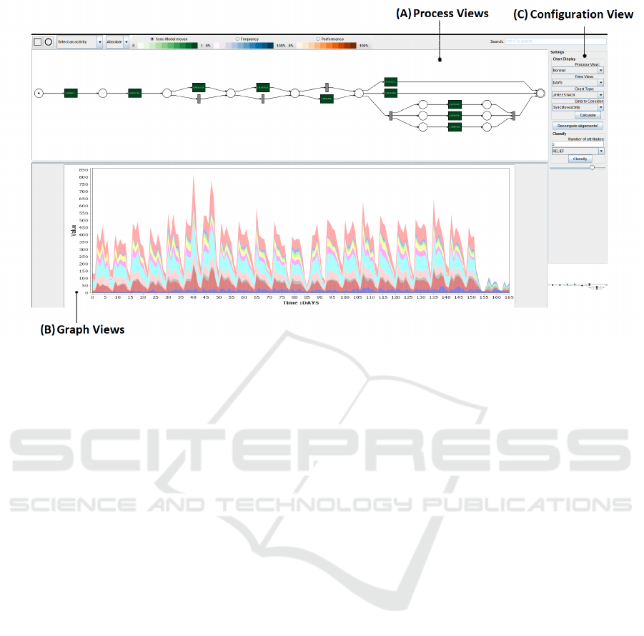
Figure 3: A snapshot of our interface. Section (A) is dedicated to the process views. The user can directly interact with the
process model. The visualizations, in Section (B), are triggered by this user interaction and by the configuration settings in
Section (C).
abstracting event logs, identifying bottlenecks, under-
standing and modeling guards in data-aware process
models, annotating and clustering cohorts by split-
ting event logs into sub logs etc. However, many of
the applications of classification techniques in process
mining focus entirely on the data perspective. As dis-
cussed above, in InterPretA, a process model is cen-
tral to everything. Hence, the classification task is
also driven from a process perspective, enabled by the
results of the conformance analysis, visualized on the
process model.
We use the traditional classification techniques in
order to perform root cause analysis, for example, to
find which resource caused a delay in the process or
what caused a deviation in a process. More particu-
larly, we support the use of pre-existing feature selec-
tion techniques, which use data attribute values (either
case level attributes or event level attributes) in order
to classify based on the desired output, for example,
values above or below a certain threshold for perfor-
mance. Furthermore, well-known ranking techniques
are used to determine the rank of each attribute based
on the ability of an attribute to classify based on the
desired output.
Besides using traditional classification and rank-
ing techniques, we use the context-aware process per-
formance analysis framework recently proposed in
(Hompes et al., 2016) to classify the event data using
functions that take the process context into account.
For example, prefixes of activities in their trace and
structural properties of the model can be used to clas-
sify activities and cases. Additionally, this technique
can help rank attributes and attribute values by means
of statistical analysis, as described in sub-section 2.5.
For example, cases that lead to statistically signifi-
cantly different conformance results can be classified
together, and features that lead to those classifications
can be ranked.
In our approach, the user interactively selects the
interesting fragments in the process model and con-
figures the classification parameters. Based on user
selection, the alignments are either recomputed, or
pre-existing alignments are used, for the classifica-
tion task. For performing the traditional classification
tasks we use Weka, which inherently supports an ar-
ray of classification algorithms (Hall et al., 2009).
2.5 Statistical Performance Analysis
Statistical analysis can be performed after classifica-
tion in order to discover whether observed differences
between different classes are statistically significant.
For example, different resources that execute an ac-
tivity might lead to significantly different execution
times, cases for patients of a specific age group might
take significantly longer than those for other patients,
waiting times might be shorter when an activity is pre-
ceded by a certain other activity, etc. When different
classes do not lead to statistically significant differ-
ent values for the chosen performance metric, classes

can be grouped in order to reduce the selection di-
mensionality for the user. Well-known statistical tests
such as analysis of variance are used here.
3 PROCESS ANALYTICS
In this section, we discuss the main application anal-
ysis enabled by InterPretA. As mentioned above, we
focus primarily on the analysis from a process per-
spective, as compared to analyzing the data from a
data perspective only. That is, a process model is cen-
tral to the analysis enabled by our technique, and the
results from conformance and performance analysis
are the primary enablers of the data analysis.
Firstly, we discuss the general analysis that can be
performed from a process perspective. Traditionally,
process based analysis can be used to identify what
is functioning correctly in the process and to analyze
where the potential problems lie in the executions of
process in reality. Process oriented analysis can be
broadly categorized into:
• Compliance analysis: The focus of compliance
analysis is to investigate questions pertaining to
auditing, adherence to business rules or protocols
etc. It should be noted that InterPretA provides
easy support for detecting generic compliance is-
sues that might exist in the process. For more so-
phisticated compliance analysis, we refer to spe-
cific techniques by (Ramezani Taghiabadi et al.,
2013; Knuplesch et al., 2013).
• Performance analysis: Performance analysis is
used to analyze the performance aspect of the
process execution. Particularly, the performance
based analysis are used to explore issues such as
identifying any bottlenecks in the process and the
steps needed to optimize the process. The need
for optimization of process is discussed in, and
motivated from (Mahaffey, 2004).
InterPretA enables both compliance oriented and
performance oriented analysis of the process. Ev-
idently, the conformance and performance analysis
are rather closely tied; and not actually independent
from each other. Firstly, InterPretA supports heli-
copter views on the process, which provide a high
level overview of the behavior of the process based on
the conformance analysis. Secondly and more impor-
tantly, InterPretA allows the user to interactively ex-
plore and perform detailed analysis of the process. In
the subsections to follow, we discuss the types of anal-
ysis enabled by InterPretA’s interface, and the config-
uration options available that correspond to each type
of analysis. We begin with the so-called views, fol-
lowed by the interactive analysis component of the
tool.
3.1 Graph Views
The event data are visualized in terms of stacked
area charts and stacked bar charts. This view is
represented in Figure 3B. We chose this representa-
tion because it makes comparisons more natural for
the user and allows rapid discovery of outliers. For
non-classification based analysis, the X-axis (domain
axis) describes the time distribution and the Y-axis de-
scribes the frequency of occurrence. The X-axis can
be sorted and configured primarily based on two view
types: absolute time and relative time. The absolute
time view shows the actual occurrence time of a par-
ticular activity, based on the conformance analysis re-
sults. Furthermore, it is possible to abstract the abso-
lute timescale into categories such as: the day of the
week when the event occurred, or the month of the
year when the event occurred etc. Alternatively, the
user can choose to view the X-axis as a relative time
axis. That is, the graph can be plotted corresponding
to the occurrence of event relative to something. For
example, the user can choose to view the distribution
of events compared to the start of the case (Figure 4),
to which the event belongs, or relative time compared
to the execution of another event in the case (Figure
5).
The X-axis of the graph view represents the con-
figurable absolute or relative timescales for the user.
The Y-axis, i.e. the frequency axis is also config-
urable. The user can choose from plotting only syn-
chronous moves, only log moves, or both the syn-
chronous and log moves in the alignment. Viewing
both synchronous and log moves essentially shows
the information from the complete event log. Figures
4 and 5 provide examples of such configuration set-
tings.
The different views on graphs lead to interesting
analysis aspects from the data. For example, one pop-
ular type of analysis enabled by our approach is con-
cept drift analysis. Concept drift analysis allows the
user to identify how a process changes over a period
of time. Considering the absolute timescale, the user
can analyze the changes in event patterns over time.
3.2 Process Views
We support three types of process views that can be
used for interactive analysis by the user (see Fig-
ure 3A). These are explained in the following sub-
sections.
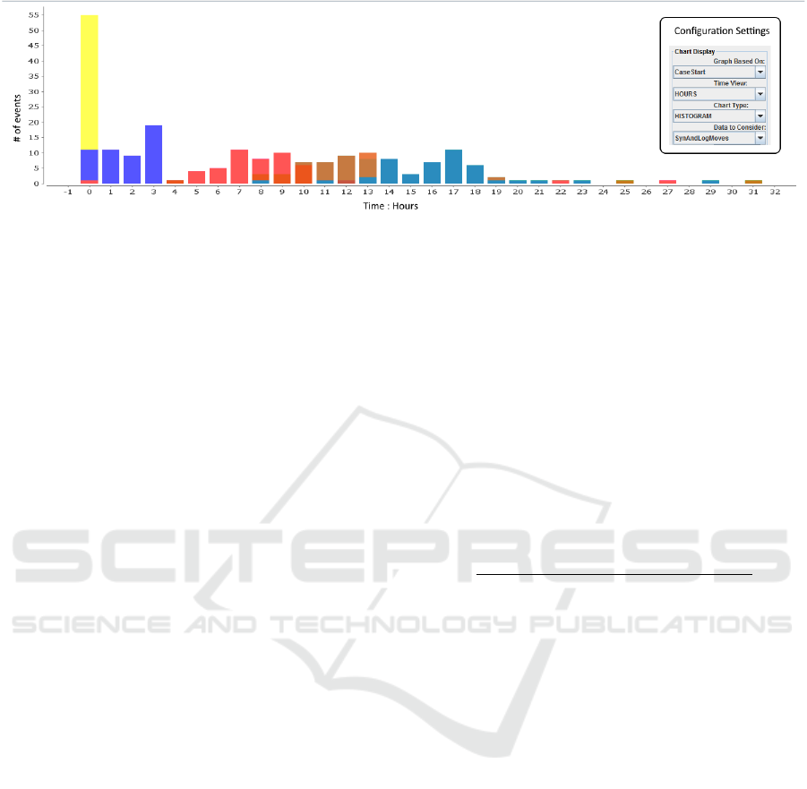
Figure 4: Graph view to show the disribution of selected activities from the process model (not shown here), since the start
of the case. Both the synchrnous and log moves are considered here, as evident from the configuration settings. The color of
each bar in histogram corresponds to every selected activity from the process.
3.2.1 Frequency View
The frequency view allows the user to get an overview
of the actual occurrence frequencies of the overall
process (e.g. Figure 6). The frequencies of occur-
rence of an activity are obtained from the alignments
projected on the process model. The frequency view
encodes the frequency of occurrence of activities in
the shades of blue, as projected on the synchronous
moves in the alignments. Darker blue and lighter
blue colors represent extremely frequent activities and
infrequent activities respectively. The user can eas-
ily identify the common and uncommon activities or
fragments in the process, based on the background
color of the activities in the process model. The fol-
lowing options are available to configure the view on
frequencies:
• Absolute View: Calculates the frequencies, based
on the absolute numbers. For example, the color
of an activity is determined by the absolute num-
ber of synchronous moves. The activity with
most number of synchronous moves is colored the
darkest. This view is similar to the default view of
the inductive visual miner (Leemans et al., 2014).
• Average Occurrence per Case View: Calculates
the frequencies, based on the average occurrences
per case. The color of the activity is determined
by the number of times the activity has a syn-
chronous move in a case, normalized over the log.
Hence, in case of a loop, if the activity has many
synchronous moves within a trace, for many cases
in the event log, then this activity would be col-
ored the darkest. Similarly, if an activity has no
synchronous moves (i.e. no corresponding event
in the event log), then it would be colored the
lightest.
• Number of Cases: Calculates the frequencies,
based on the number of cases for which the syn-
chronous move occurred. The color of an activity
is determined by the ratio of the number of cases
for which synchronous moves occurred over the
total number of cases in the event log.
3.2.2 Fitness of Model and Log View
The fitness of model and log view is derived based on
the synchronous and model moves, along with the log
moves in the process model. This view represents the
fitness of event log and process model. The activities
are colored in the shades of green. The actual color
of an activity is dependent on the ratio of:
#Synchronous moves
#Model Moves + #Synchronous moves
(1)
Hence, darker shade of green for an activity in a
model imply that the particular activity had more syn-
chronous moves than model moves, i.e. it is described
very well according to the model. As with the fre-
quency view, fitness of model and log is configurable
to obtain different views. That is, the activities can
be colored based on the ratio of absolute occurrences
of synchronous and model moves, or the ratio of av-
erage occurrences of synchronous and model moves
per case, or the ratio of number of cases for which
synchronous and model move occurred.
3.2.3 Performance View
The frequency and fitness views enable the user to
easily investigate the common and uncommon paths
and deviations in the process. However, the perfor-
mance view allows the user to investigate the stages of
the process where bottlenecks occur, or where there is
room for improvement. In the performance view, the
activities are labeled in the shades of red. The shade
depends on the execution time between the immedi-
ate previous synchronous activity and the current syn-
chronous activity for every case. The darker shades
of red imply that the synchronous versions were ex-
ecuted after a long delay since the completion of the
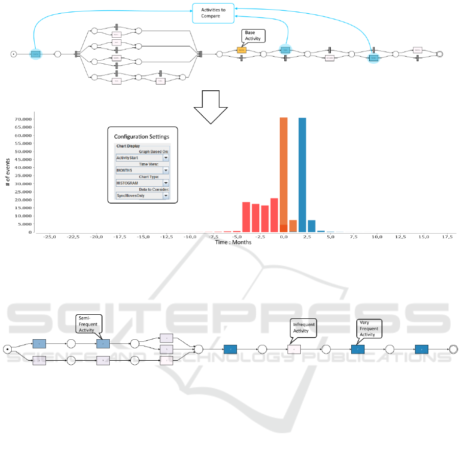
Figure 5: Graph view to compare the distribution of activities with respect to a selected activity. A single activity from the
process view is chosen by the user as the base activity, followed by a number of activities which should be compared with the
base activity. The histogram shows the time distribution and the number of times the selected activities to be compared occur,
before or after the base activity. The color of each bar in histogram corresponds to each selected activity from the process. It
should be noted that the base activity always occurs at time 0 and is not shown in the histogram view.
Figure 6: An example of frequency view of the process model. The more frequent activities/paths could be easily visualized
in the model. The user can use this information to interactively explore the specific details pertaining to the frequent tasks.
previous synchronous activities. As with the fitness of
model and log, the user can configure different views
(absolute, average occurrence per case or number of
cases) on the performance dimension.
It should be noted that the transactional informa-
tion of an activity (e.g. events representing lifecycle
an activity) can also be used for performance anal-
ysis. That is, the lifecycle information of an activ-
ity is useful in detecting the actual performance time
of an activity. However, we do not show this infor-
mation on the helicopter performance view as often
event logs only contain complete events, i.e. only one
event per activity instance. When lifecycle informa-
tion is present, additional performance statistics are
calculated and can be shown.
3.3 Interactive Analysis
The graph views and process views enable analysis
of the process from a high level. In a typical process
analytic setting, the user is also interested in perform-
ing a detailed root cause analysis. In this section,
we describe how InterPretA supports the user in
performing such detailed analysis starting from the
high-level views. Five high-level tasks (Schulz et al.,
2013) have been identified to perform the interactive
analysis.
Task 1: Deviation Analysis. The fitness of model and
log view provides a good overview of how well the
data and model fit, and where the possible deviations
are located in the process. The next step would be to
investigate what causes the deviations in the process.
For example, suppose that the conformance analysis
indicates that a particular task is sometimes skipped
(move on model) in the process. This could be ex-
plained by the attributes associated with the case, for
example the resources performing the task.
In order to investigate what or who causes
deviations in the process, classification analysis
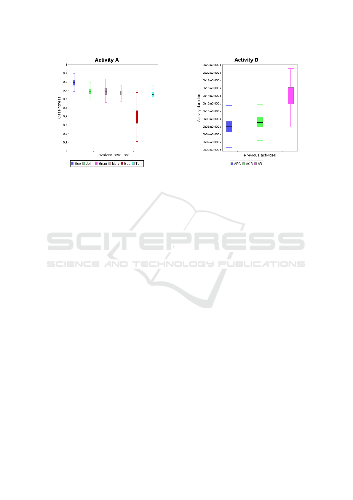
Figure 7: Compliance analysis for resources involved in ac-
tivities. When resource ‘Bob’ is involved in activity ‘A’, the
case fitness to the model is significantly lower.
is used. The user can select the desired activity
from the activity drop down list, and configure the
desired classification settings, to classify what or
who causes the synchronous, log and model moves
for the particular activity. Here, we make use of
the context-aware performance analysis framework
proposed in (Hompes et al., 2016) to provide and
rank the statistically significant attributes (i.e. the
process context). Many combinations of classifi-
cation and performance/conformance functions are
automatically generated from a collection of contexts.
Then, statistical testing is automatically performed
to verify whether different classes (contexts) lead
to statistically significantly different results, e.g. in
Figure 7, we see that Bob has a high variability in
activity A. For those combinations where this is
the case, the specific classification is returned to
the user as it might lead to interesting insights. For
example, Figure 7 shows an example plot of the
fitness of a model, split by the different resources
that can perform activity ‘A’ in the process. From
this example, we might deduce that the fitness of a
case to the model depends highly on which resource
executes activity ‘A’. The statistical analysis tells
us which resource(s) lead to significantly different
results.
Task 2: Bottleneck Analysis. The performance view
provides an overview of the time spent between the
activities. For example, it may be the case that a
particular path in a process is much slower than the
other paths. The user might be interested in finding
out, how a particular path with delays is different
from other paths in the process. In order to find this
out, the user can select the activities from the process
Figure 8: Bottleneck analysis for activities preceding a bot-
tleneck activity ‘D’. When activity ‘C’ is not performed be-
fore activity ‘D’, the duration is significantly longer.
model which correspond to the path with delays.
Next, the user can perform classification analysis,
with the output of classification set to be fitting ver-
sus non-fitting cases. The fitting cases in the output
would be the ones which have the synchronous moves
for all the selected activities. Alternatively, the user
might be interested in finding out all the cases in the
process (or a path in the process) which are executed
within a certain time frame. For such analysis, the
output for classification could be a threshold for time
taken, such that the attributes which better define
the performance (e.g. above or below the threshold
for time taken) would be identified by the classifi-
cation techniques. Alternatively, we automatically
verify whether different contexts lead to significant
differences in performance. For example, Figure 8
shows an example where the duration of an activity
is significantly different for different prefixes in the
trace. From this example, we might conclude that
activity ‘C’ should be made mandatory.
Task 3: Frequency-oriented Compliance Analysis.
The frequency view on process model gives a good
overview of the frequency distribution of activities in
the overall process. This view is already useful for an-
swering some compliance questions such as whether
or not an activity occurs at least once for every
case. However, the user might also be interested in
interactively investigating some non-trivial KPIs such
as the occurrence of a particular activity triggering
the occurrence of another activity. In order to enable
such analysis, the user can select a set of activities,
and select the appropriate configuration settings,
to check the co-occurrences and the frequencies of
co-occurrence for selected activities. Additionally,
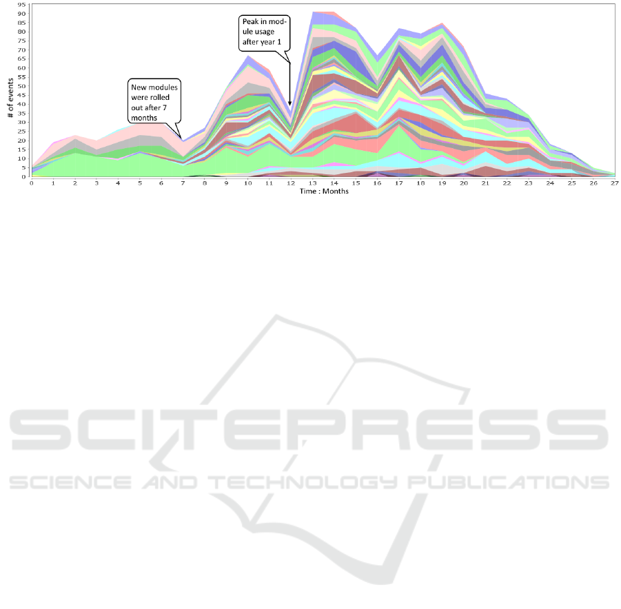
Figure 9: Graph showing the concept drift and changes among different modules in the LUMC dataset. The colors in the
graph correspond to an activity belonging to a particular module. For first 7 months, all the activities belonged to one module
type. There is a steep fall in the module usage towards year end and a peak in the module usage in year 2.
the user can view differences in performance for
different classes.
Task 4: Performance-oriented Compliance Anal-
ysis. The performance view allows the user to easily
investigate the overall time between activities and/or
where the bottlenecks may be in the process. How-
ever, there could be some time-critical KPI analysis
that the user might be interested in. For example,
a certain activity ‘B’ should be performed within
x-hours after executing an activity ‘A’. The user can
select the activity ‘A’, and activity ‘B’ (among others
if needed), to visualize the time span of occurrence
distributions of ‘B’ with respect to ‘A’. Different
contexts can be tested for their impact significance on
the time between the two activities.
Task 5: Process Fragmentation. The user might
also be interested in exploring certain fragments of
a process. That is, instead of considering the align-
ments on the complete process model, the user might
only be interested in investigating how the process
behaves, corresponding to only a few activities. In
order to achieve this, the user can select the interest-
ing activities, and re-compute the alignments only for
such activities. The re-computed alignment would
consider the moves only for the selected activities,
and all the other moves would either be ignored or
considered model moves with zero cost. Based on
the fragmented process view, and the alignments
based on filtered model, all the previous analysis
could be repeated. An example of such task can
be derived from Figure 5, wherein the user selects
some activities (marked blue). The user may then
re-compute alignments only for the selected activities.
4 CASE STUDY
As a part of evaluating our approach, we perform
analysis on a real-life dataset from a diabetes treat-
ment care process, provided by a Dutch hospital -
Leiden University Medical Center (LUMC). In or-
der to cope with unstructured processes as discussed
in (Fernandez-Llatas et al., 2015), LUMC has pro-
posed and rolled out six specialized modules as a part
of its diabetes treatment plan process. Each module
can be viewed as a separate process, each consisting
of a series of appointments, some of which may be
skipped and some of which may occur in any order.
The HIS used by LUMC records all the relevant infor-
mation about the appointments in each of these mod-
ules. The event log created from the HIS logs spans
over more than 2.5 years, and involves almost 300
cases (patients). The data was anonymized by using
pseudonymised patient ids. Using this information,
we perform both exploratory analysis, and also an-
swer some compliance and performance related ques-
tions. Rather than splitting the log into sub-logs cor-
responding to each module type, we use the complete
event log and use the inductive miner infrequent pro-
cess discovery algorithm (Leemans and Aalst, 2014)
to discover a process model, containing all the mod-
ules together.
4.1 Analyzing Change of Modules
By plotting the data for all the events, of all the mod-
ules, its easy to visualize the patterns of changes in
the types of module over time. The domain axis was
sorted to contain the absolute time span from low-
est to highest, represented in terms of months. From
Figure 9, it can easily be concluded that for the first
few months (approximately until 7 months), only one
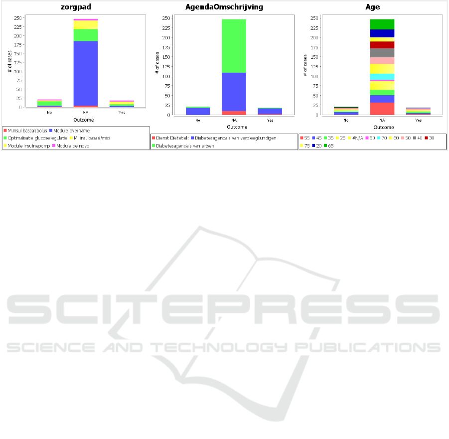
Figure 10: The top three ranked attribute classifiers for the classification analysis based on the answers to the question Were
the personal goals met?. The top ranked attribute classifier based on the ranking algorithm was zorgpad (i.e. module type).
module existed, as all the activities within this time
span belong to the same module type. From Figure 9
it can also be seen that this module still persisted over
time, but was gradually replaced by the other mod-
ules. One more interesting pattern that could be ob-
served from Figure 9, is the decrease in the number
of events towards the end of the timeline. A logical
explanation for this pattern is that since the appoint-
ments (events) for modules are usually scheduled in
the future, a more distant future has fewer number of
appointments.
4.2 Classification Analysis
At the end of each module, the patients are asked to
fill in a questionnaire, evaluating the patients treat-
ment plan, understanding and satisfaction of the mod-
ule. It is interesting to analyze the outcome of the
treatment, based on the answers in the survey. For one
of such questions, Were the personal goals met?, we
perform classification analysis with the Information
gain classifier, and answers to question (Yes, No or
NA) as output. The top three ranked attributes which
best classify the output are shown in Figure 10. It
is however important to note that module overname
is a basic module (to meet diabetic team members)
and hence majority of the patients from such modules
have not reached their goals yet, thereby having the
corresponding value of NA, as shown in Figure 10.
We select the top ranked attribute classifier, found to
be the module type. For the majority of patients, no
value was recorded for this question (value of NA).
However, for the patients who did fill in the survey,
one prominent outcome, as evident from Figure 11
is that for the module Optimalisatie glucoseregulatie,
almost twice the amount of patients did not meet their
expectations fully. This suggests that another module
might have been more suitable or calls for improve-
ment in the module to better manage the patient ex-
pectation.
4.3 Compliance Analysis - Time
Perspective
Next, we focus on one individual module, to perform
some preliminary compliance analysis. The expecta-
tion is to have every appointment completed within a
certain time-frame. We select a particular appoint-
ment type from the chosen module and plot a his-
togram with domain axis showing the time in weeks,
since the beginning of the case. Ideally, the chosen
activity should be completed within 9-10 weeks since
the start of the case. However, as becomes clear from
Figure 12, in reality this activity is mostly completed
before the expected time duration, thereby meeting
the desired KPI for majority of the patients.
5 CONCLUSION AND FUTURE
WORK
In this paper, we introduced a novel tool for enabling
interactive process-oriented data analysis. The tool
builds upon and brings together existing techniques
from process mining, data mining and visual analyt-
ics field, to enable interactive process analysis. It
supports exploratory analysis through different heli-
copter views on the process. In contrast to existing
approaches, it is highly interactive, which could be
used to perform root cause analysis for any problems
in the process. The application areas of the tool are
broadly categorized, and the tool was utilized to an-
alyze a real-life dataset. The tool relies on the tradi-
tional ways of representing the data (e.g. histograms)
for process analytics.
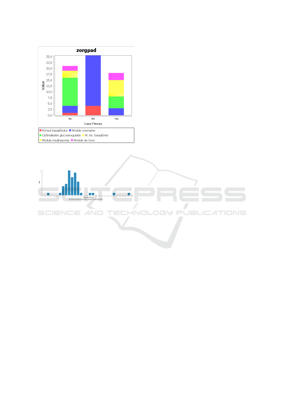
Figure 11: Zoomed in version showing responses for Yes
and No, for the top ranked classifier zorgpad (module type)
based on the answer to the question Were the personal goals
met?.
Figure 12: Compliance analysis for completetion of the ac-
tivity.
In the future, we aim to support more interac-
tive data exploration, for example from the plotted
graphs views. Currently the tool is limited to read-
only data plots in terms of histograms/stacked charts.
Drill down and roll up analysis could be introduced,
to support more data-oriented task analysis. Further-
more, the impact on the current process could be vi-
sualized based on the interaction of the user with the
data from the graph view. This could also lead to un-
derstanding the configurability of the process based
on certain cohorts. Another research direction would
be to introduce more classification and/or correlation
strategies. Currently, we consider only one classifier
attribute at a time. One obvious next step would be
to also consider the combined impact of multiple at-
tributes on the output variable for classification. Here,
statistical analysis would also be a beneficial addition.
ACKNOWLEDGEMENTS
The authors would like to thank LUMC for provid-
ing the problems and the access to the data. The au-
thors especially thank Drs. Marielle Schroijen and
A.J. (Thomas) Schneider, both from LUMC, for their
efforts, thorough help and timely feedback throughout
the analysis. Furthermore, the authors would like to
thank Philips research and Technical University Eind-
hoven for funding this research.
REFERENCES
Aalst, W. M. P. v. d. (2016). Process Mining - Data Science
in Action, Second Edition. Springer.
Aalst, W. M. P. v. d., Leoni, d. M., and ter Hofstede, A. H.
(2011). Process mining and visual analytics: Breath-
ing life into business process models.
Adriansyah, A., Dongen, B. F. v., and Aalst, W. M. P. v. d.
(2011). Towards robust conformance checking. In
Business Process Management Workshops, volume 66
of Lecture Notes in Business Information Processing,
pages 122–133. Springer Berlin Heidelberg.
Buffett, S. and Geng, L. (2010). Using classification meth-
ods to label tasks in process mining. Journal of
Software Maintenance and Evolution: Research and
Practice, 22(6-7):497–517.
Dongen, B. F. v., de Medeiros, A. K. A., Verbeek, H. M. W.,
Weijters, A. J. M. M., and Aalst, W. M. P. v. d. (2005).
The prom framework: A new era in process min-
ing tool support. In International Conference on Ap-
plication and Theory of Petri Nets, pages 444–454.
Springer.
Dwivedi, A., Bali, R., James, A., and Naguib, R. (2001).
Workflow management systems: the healthcare tech-
nology of the future? In Engineering in Medicine and
Biology Society, 2001. Proceedings of the 23rd An-
nual International Conference of the IEEE, volume 4,
pages 3887–3890. IEEE.
Fernandez-Llatas, C., Martinez-Millana, A., Martinez-
Romero, A., Bened, J. M., and Traver, V. (2015). Di-
abetes care related process modelling using process
mining techniques. lessons learned in the application
of interactive pattern recognition: coping with the
spaghetti effect. In 2015 37th Annual International
Conference of the IEEE Engineering in Medicine and
Biology Society (EMBC), pages 2127–2130.
Goedertier, S., Martens, D., Baesens, B., Haesen, R., and
Vanthienen, J. (2007). Process mining as first-order
classification learning on logs with negative events. In
International Conference on Business Process Man-
agement, pages 42–53. Springer.
Graeber, S. (1997). The impact of workflow management
systems on the design of hospital information systems.
In Proceedings of the AMIA Annual Fall Symposium,
page 856. American Medical Informatics Association.
Hall, M., Frank, E., Holmes, G., Pfahringer, B., Reutemann,
P., and Witten, I. H. (2009). The weka data min-
ing software: An update. SIGKDD Explor. Newsl.,
11(1):10–18.

Hompes, B. F. A., Buijs, J. C. A. M., and Aalst, W. M.
P. v. d. (2016). A Generic Framework for Context-
Aware Process Performance Analysis, pages 300–317.
Springer International Publishing, Cham.
Knuplesch, D., Reichert, M., Ly, L. T., Kumar, A., and
Rinderle-Ma, S. (2013). Visual Modeling of Business
Process Compliance Rules with the Support of Multi-
ple Perspectives, pages 106–120. Springer Berlin Hei-
delberg, Berlin, Heidelberg.
Kriglstein, S., Pohl, M., Rinderle-Ma, S., and Stallinger, M.
(2016). Visual Analytics in Process Mining: Classifi-
cation of Process Mining Techniques. In Andrienko,
N. and Sedlmair, M., editors, EuroVis Workshop on
Visual Analytics (EuroVA). The Eurographics Associ-
ation.
Leemans, S. J. J., F. D. and Aalst, W. M. P. v. d. (2014). Dis-
covering block-structured process models from event
logs containing infrequent behaviour. In Business Pro-
cess Management Workshops, pages 66–78. Springer.
Leemans, S., Fahland, D., and Aalst, W. M. P. v. d. (2014).
Process and deviation exploration with inductive vi-
sual miner.
Leoni, M. d., Maggi, F., and Aalst, W. M. P. v. d. (2015). An
alignment-based framework to check the conformance
of declarative process models and to preprocess event-
log data. Information Systems, 47:258 – 277.
Mahaffey, S. (2004). Optimizing patient flow in the enter-
prise. Health management technology, 25(8):34–37.
Mannhardt, F., de Leoni, M., and Reijers, H. (2015). The
multi-perspective process explorer. In Proceedings
of the BPM Demo Session 2015, Co-located with
the 13th International Conference on Business Pro-
cess Management {(BPM} 2015), Innsbruck, Austria,
September 2, 2015, pages 130–134. CEUR Workshop
Proceedings.
Munoz-Gama, J., Carmona, J., and Aalst, W. M. P. v. d.
(2014). Single-entry single-exit decomposed confor-
mance checking. Information Systems, 46.
Poggi, N., Muthusamy, V., Carrera, D., and Khalaf, R.
(2013). Business process mining from e-commerce
web logs. In Business Process Management, pages
65–80. Springer.
Ramezani Taghiabadi, E., Fahland, D., Dongen, B. F. v.,
and Aalst, W. M. P. v. d. (2013). Diagnostic Informa-
tion for Compliance Checking of Temporal Compli-
ance Requirements, pages 304–320. Springer Berlin
Heidelberg, Berlin, Heidelberg.
Schulz, H.-J., Nocke, T., Heitzler, M., and Schumann, H.
(2013). A design space of visualization tasks. IEEE
Transactions on Visualization and Computer Graph-
ics, 19(12):2366–2375.
Sutherland, J. and van den Heuvel, W. (2006). Towards an
intelligent hospital environment: Adaptive workflow
in the or of the future. In Proceedings of the 39th An-
nual Hawaii International Conference on System Sci-
ences (HICSS’06), volume 5, pages 100b–100b.
Weigl, M., M
¨
uller, A., Vincent, C., Angerer, P., and Sev-
dalis, N. (2012). The association of workflow inter-
ruptions and hospital doctors’ workload: a prospective
observational study. BMJ quality & safety, 21(5):399–
407.
