
Complete Code Generation from UML State Machine
Van Cam Pham, Ansgar Radermacher, S
´
ebastien G
´
erard and Shuai Li
CEA, LIST, Laboratory of Model Driven Engineering for Embedded Systems, P.C. 174, Gif-sur-Yvette, 91191, France
Keywords:
UML State Machine, Code Generation, Semantics-conformance, Efficiency, Events, C++.
Abstract:
An event-driven architecture is a useful way to design and implement complex systems. The UML State
Machine and its visualizations are a powerful means to the modeling of the logical behavior of such an archi-
tecture. In Model Driven Engineering, executable code can be automatically generated from state machines.
However, existing generation approaches and tools from UML State Machines are still limited to simple cases,
especially when considering concurrency and pseudo states such as history, junction, and event types. This
paper provides a pattern and tool for complete and efficient code generation approach from UML State Ma-
chine. It extends IF-ELSE-SWITCH constructions of programming languages with concurrency support. The
code generated with our approach has been executed with a set of state-machine examples that are part of a
test-suite described in the recent OMG standard Precise Semantics Of State Machine. The traced execution
results comply with the standard and are a good hint that the execution is semantically correct. The generated
code is also efficient: it supports multi-thread-based concurrency, and the (static and dynamic) efficiency of
generated code is improved compared to considered approaches.
1 INTRODUCTION
The UML State Machine (USM) (Specification and
Bars, 2007) and its visualizations are efficient to
model the behavior of event-driven architecture.
Tools and approaches are proposed to automatically
translate USMs into executable code in the context
of Model-Driven Engineering (MDE) (Mussbacher
et al., 2014).
However, despite many advantages of MDE and
USM, they are not widely adopted as a recent survey
revealed (Whittle et al., 2014). This is partially due
to poor support for code generation (Forward et al.,
2010).
On one hand, the usefulness and semantics of
USM are being empowered by OMG by providing
more concepts and their precise semantics such as
pseudo states and composite state machines. On the
other hand, existing code generation tools and ap-
proaches have some issues regarding completeness,
semantics and efficiency of generated code. Existing
approaches either support a subset of USM modeling
concepts or handle composite state machines by flat-
tening into simple ones with a combinatorial explo-
sion of states, and excessive generated code (Badred-
din et al., 2014a). Specifically, the following lists
some of the current issues:
Completeness: Existing tools and approaches mainly
focus on the sequential aspect while the concurrency
of state machines is limitedly supported. Pseudo
states are not rigorously supported by existing tools
such as Rhapsody (IBM, 2016a). Designers are then
restricted to a subset of USM concepts during design.
Efficiency: Code generated from tools such as
Rhapsody (IBM, 2016b) and FXU (Pilitowski and
Derezi
˜
nska, 2007) depends on the libraries provided
by the tool vendor, which makes the generated code
non portable. Event processing speed and executable
file size of generated code are not optimized (Charfi
et al., 2012).
Semantics: The semantics of UML State Machine
is defined by a recent OMG-standardized: Precise
Semantics of State Machine (PSSM) (OMG, 2016).
This standard is not (yet) taken into account for val-
idating the runtime execution semantics of generated
code.
Given the above issues, the objective of this paper
is to present a novel code generation pattern and its
tooling support. The latter offers efficient code gen-
erated from USMs with full concepts to reduce the
modeling-implementation gap.
The proposed pattern extends IF-ELSE construc-
tions with our support for concurrency. Runtime ex-
ecution of generated code is experimented with the
208
Pham V., Radermacher A., GÃl’rard S. and Li S.
Complete Code Generation from UML State Machine.
DOI: 10.5220/0006274502080219
In Proceedings of the 5th International Conference on Model-Driven Engineering and Software Development (MODELSWARD 2017), pages 208-219
ISBN: 978-989-758-210-3
Copyright
c
2017 by SCITEPRESS – Science and Technology Publications, Lda. All rights reserved

PSSM test suite.
To sum up, the contributions of this paper are: (1)
an approach and tooling support for code generation
from USMs with full features; (2) an empirical study
on the semantic-conformance and efficiency of gen-
erated code; and (3) application of the tool to a case
study.
We assume that readers of this paper have knowl-
edge about UML State Machine and its basic execu-
tion semantics.
The remaining of this paper is organized as fol-
lows: Section 2 describes the modeling of applica-
tions using UML State Machines. Section 3 mentions
the features of our tool. Thread-based concurrency
is designed in Section 4. Based on this design, a code
generation approach is proposed in Section 5. The im-
plementation and empirical evaluation are reported in
Section 6. The application of our tool to a case study
is presented in Section 7. Section 8 discusses related
work. The conclusion and future work are presented
in Section 9.
2 STATE MACHINES AND UML
EVENTS
This section presents overview of using UML State
Machines for modeling and designing reactive soft-
ware applications. A state machine is used for de-
scribing the behavior of either a class in object-
oriented design or a component in component-based
design. In the following, we commonly use the term
class.
The state machine processes external and internal
events. UML defines four event types: CallEvent,
SignalEvent, TimeEvent, ChangeEvent. A call event
is associated with an operation/method and emitted
if the operation is invoked. The processing of call
events is synchronous meaning that it runs within the
thread of the operation caller. The processing of other
events is asynchronous meaning that these events re-
ceived by the class are stored in an event queue which
is maintained by the class at runtime for later process-
ing. A signal event is associated with a UML signal
type containing data. It is emitted if the class receives
an instance of the signal type. From a programming
perspective, we provide an API sendSignal to send
the signal instance from environment code or other
classes to the class and store the event in the queue.
A time event specifies the time of occurrence rela-
tive to a starting time. The latter is defined as the time
when a state with an outgoing transition triggered by
the time event is entered. The time event is emit-
ted if this accepting state remains active longer that
the relative time of occurrence. Once emitted, it trig-
gers the transition. In other words, the state, which is
the source vertex of a transition triggered by a time
event, will remain active for a maximal amount of
time specified by the time event. A change event has
a boolean expression and is fired if the expression’s
value changes from false to true. Note that unlike call
and signal events, time and change events are auto-
matically fired inside the class.
Deferred Events: A state can specify to defer some
events. It means that if an event specified as deferred,
it will be not processed while the state remains ac-
tive. The deference of events is used to postpone the
processing of some low-priority events while the state
machine is in a certain state.
We support all of these events to model event-
driven reactive applications.
3 FEATURES
Our pattern and tool has some features compared to
other tools as followings:
Completeness: Our tool supports all state machine
vertexes and transitions including all pseudo states
and transition kinds such as external, local, and in-
ternal. Hence, the tool improves flexibility of using
UML State Machines to express architecture behav-
ior. For the moment, our tool cannot deal with transi-
tions from an entry point to an exit point. We believe
that these transitions are not used in reality. This is be-
cause the contradictory semantics of entry points and
exit points. In UML, entry points and exit points rep-
resent entering points and exit points of a compoiste
state, respectively. They provide encapsulation of the
insides of the state. The entry points allow users to
customize the way to enter the composite state instead
of the default entering way while the exit points allow
to customize the exiting way. For example, the Enp
entry point in Fig. 1 allows the S5 sub-state of the
S1 composite state to be active instead of S3 by the
default entering way.
Event Support: Our tool promotes four UML event
types and event deference mechanism, which are able
to express synchronous and asynchronous behaviors
and exchange data between components/classes.
UML-conformance: A recent specification formal-
izing the Precise Semantics of UML State Machine
(PSSM) is under standardization of the OMG. It de-
fines a test suite with 66 test cases for validating the
conformance of runtime execution of code generated
from UML State Machines. We have experimented
our tool with the test suite. Traced execution results
Complete Code Generation from UML State Machine
209

of 62/66 test cases comply with the standard and are,
therefore, a good hint that the execution is semanti-
cally correct.
State Machine Configuration: Asynchronous
events such as signal events, change events, and time
events are stored in an event queue. A signal event
can bring data (message). Our tool allows to con-
figure the event queue size and the maximal size of
signals. The configuration is not specified by UML
because the specification wants to be abstract. We al-
low to determine these values through a specific pro-
file. Note that the configuration information might not
be needed in dynamic memory allocation. The latter,
however, is not recommended in embedded systems.
Efficiency: We conducted experiments on some
benchmarks to show that code generated by our tool
is efficient and can be used to develop resource-
constrained embedded software. Specifically, event
processing is fast and the size of executable files com-
piled from generated code is small.
Event API: Generated code in our tool provides APIs
for environment code to invoke operations or send
data signals to reactive classes. The invocations and
sending will automatically fire events for state ma-
chines to process.
Concurrency: Concurrency aspects in state ma-
chines including doActivity of states, orthogonal re-
gions, event detection, and event queue management
are handled by the execution of multiple threads. Cur-
rently, we use POSIX threads for concurrency.
Portability: Currently, our tool generates C++ code.
The generated code can run on POSIX systems such
as Ubuntu without installing any additional libraries
to be able to compile and execute the code. Our code
generation pattern and tool can be extended to gener-
ate code in other programming languages such as Java
which supports threads and mutexes for multi-thread
synchronization.
4 CONCURRENCY
This section describes our design of concurrency as-
pects of state machines in generated code at runtime.
4.1 Thread-based Design
The concurrency of USMs is based on multi-
ple threads including permanent and spontaneous
threads. While permanent threads (PTs) are created
once and live as long as the state machine is alive,
spontaneous threads (STs) are spawned and active for
a while. Each PT is initialized at the state machine
initialization. The design of threads is based on the
thread pool pattern, which initializes all threads at
once, and the paradigm ”wait-execute-wait”. In the
latter, a thread waits for a signal to execute its asso-
ciated method and goes back to the wait point if it
receives a stop signal or its associated method com-
pletes. Each PT is associated with one of the follow-
ing actions:
• doActivity of each state if has any.
• Sleep function associated with a time event which
counts ticks and emits the event once completes.
• Change detect function associated with a change
event which observes a variable or a boolean ex-
pression and pushes an event to the queue if a
change occurs.
• State machine main thread, which reads events
from the event queue, and sends start and stop sig-
nals to other PTs.
STs which are spawned by a parent thread, joined
until and destroyed once the associated methods com-
plete. The STs follow a paradigm in which the spawn-
ing parent must wait until its children complete their
associated methods. These threads are used for the
following cases:
• A thread is created for each effect of transitions
outgoing from a fork or incoming to a join.
• Entering a concurrent state, after the entry action
of the state, a thread is created for each orthogonal
region.
• Exiting a concurrent state, before the exit action
of the state, a thread is created for each region to
exit the corresponding active sub-state.
4.2 Thread Communication
Each PT is associated with a mutex for synchroniza-
tion in the multi-thread-based generated code. The
mutex must be locked before the method associated
with the thread is executed.
Run-to-completion: The event process must follow
the run-to-completion semantics of UML State Ma-
chines. The semantics means that the state machine
completes processing of each event before starting
processing the next event. If all events are asyn-
chronous, the main thread processes events by read-
ing one-by-one from the event queue. However, be-
cause we allow call events to be synchronous, the pro-
cessing of synchronous and asynchronous events can
violate the run-to-completion semantics. To avoid it,
a main mutex is associated with the main thread to
protect the run-to-completion semantics. Each event
processing must lock the main mutex before execut-
ing the actual processing. In generated code, lock and
MODELSWARD 2017 - 5th International Conference on Model-Driven Engineering and Software Development
210
Listing 1: IState interface and function pointers in C++.
1 t y pe d e f s t r u c t I S t a t e {
i n t p r e v i o u s A c t i v e s [ 2 ] ; i n t a c t i v e s [ 2 ] ;
3 } I S t a t e ;
c l a s s C {
5 p r i v a t e :
I S t a t e s t a t e s [STATE MAX ] ;
7 p u b li c :
v o i d e n t r y ( S t a t e I d i d ) {
9 s w i t ch { i d } {
c a s e S0 ID :
11 / / a c t i o n c o d e f o r e ac h s t a t e
break ;
13 / / c od e f o r o t h e r s t a t e a c t i o n s
}
15 }
}
unlock are implemented using signals and conditions
in POSIX (Butenhof, 1997).
5 CODE GENERATION PATTERN
This section describes our code generation pattern for
states, regions, events, and transitions.
5.1 State
A common state type IState is created. The type has
two attributes called actives, to preserve the hierarchy
of composite states, and previousActives referring to
current and previous active sub-states in case of the
presence of history states. Each UML state is trans-
formed into an instance of IState and a state ID is as-
signed (which is a child element of an enumeration).
During initialization, each instance initializes its at-
tributes to a default value meaning inactive state.
In the following sections, we only consider C++
as a specific generated language. The discussion of
other object-oriented languages is much similar since
these share the same concepts.
Listing 1 shows the state type and its instances.
STATE MAX is the number of states. The state actions
such as entry/exit/doActivity are generated to corre-
sponding common methods containing action codes.
For example, entry in the listing implements all of the
state action codes.
State doActivitys, as specified by UML, are run
concurrently. Each doActivity is then run within a
permanent thread and a mutex is created for control-
ling it. Listing 2 shows a code segment for doActivity
threads. The method doActivityThread takes as input
a state id to use and call the appropriate mutex and
doActivity, respectively. The method does nothing
and stays in a waiting point if the state correspond-
ing to the input parameter state identifier is inactive
(line 5). If the state is active, a start signal is sent to
this thread method to start the execution of doActiv-
Listing 2: Example code generated for doActivity.
w h il e ( t r u e ) {
2 p t h r e a d m u t e x l o c k (& mut ex [ s t a t e I d ] ) ;
w h il e ( ! i s S t a r t s [ s t a t e I d ] ) {
4 / / a w a i t s t a r t s i g n a l
p t h r e a d c o n d w a i t (&cond , &mut ex [ s t a t e I d ] ; }
6 d o A c t i v i t y ( s t a t e I d ) ;
i s S t a r t s [ s t a t e I d ] = f a l s e ; / / r e s e t w ai t f l a g
8 p t h r e a d m u t e x u n l o c k (&mutex [ s t a t e I d ] ) ;
i f ( ! i s S t o p s [ s t a t e I d ] ) {
10 i f ( s t a t e I d ==S0 ID | | . . . ) { / / a t o m i c s t a t e s
p u sh Co m pl et i on Ev e nt ( s t a t e I d ) ;
12 }
}
14 }
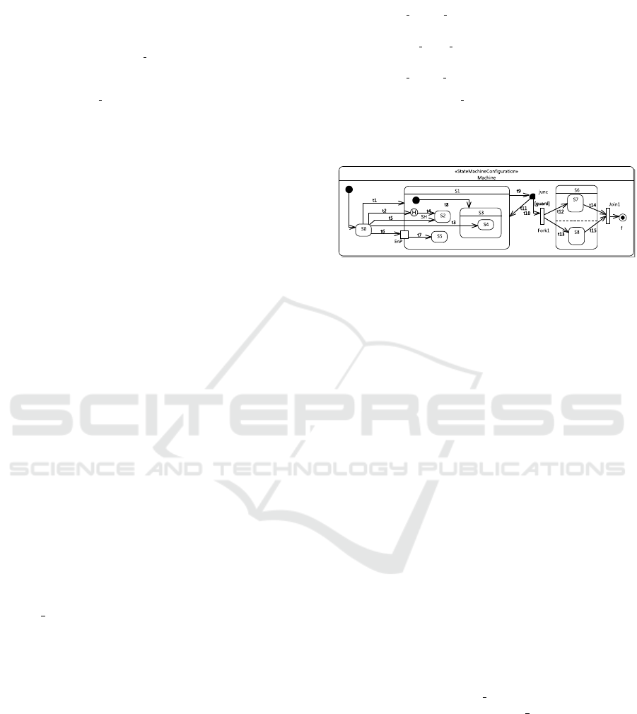
Figure 1: Example illustrating different ways entering a
composite state.
ity. The generated code typically follows the common
paradigm in POSIX threads (Butenhof, 1997).
5.2 Region
Our approach considers regions as elements to be
transformed. Specifically, each region has two meth-
ods: entering and exiting. The entering method con-
trols how a region r is entered from an outside transi-
tion and the exiting method exits completely a region
by executing exit actions of sub-states from innermost
to outermost.
A region can be entered two different ways: (1)
entering by default: the transition ends at the border
of composite states; and (2) cross transition: enter-
ing at a direct or an indirect sub-vertex of composite
states. The two entering ways execute the entry ac-
tion of the containing composite state after the tran-
sition effect. The executions afterwards are different
for each way. To illustrate, we use an example as in
Fig. 1 with S1 as a target composite state. t1 is in the
way (1) while t2, t5, t6 in the way 2.
The entering method associated with the region of
S1 has a parameter enter mode telling how the en-
tering should be executed. enter mode takes values
depending the number of transitions coming to the
composite state. The detail of how these modes are
implemented in specific languages are not discussed
here. Listing 3 shows the generated C++.
By default, the region’s active sub-state is set after
the execution of any effect associated with the initial
transition. Therefore, S3 is set as active sub-state of
S1. Entering at (S2) sets the active sub-state of S1 di-
rectly to S2. In case of an indirect sub-state (S4), the
Complete Code Generation from UML State Machine
211

Listing 3: Example code generated for the region of S1.
v o i d S 1 Re gi on 1 En te r ( i n t e n t e r m o d e ) {
2 i f ( e nt er m od e == DEFAULT) {
s t a t e s [ S1 ID ] . a c t i v e s [ 0 ] = S3 ID ;
4 e n t r y ( S3 ID ) ; s e n d S t a r t S i g n a l ( S3 ID ) ;
S 3 Re g io n 1E n te r (DEFAULT ) ;
6 } e l s e i f ( e nt er m o d e == S2 MODE) {
/ / . .
8 } i f ( e nt er m od e == SH MODE ) {
StateIDEnum h i s ;
10 i f ( s t a t e s [ S1 ID ] . p r e v i o u s A c t i v e s [ 0 ] ! =
STATE MAX ) {
h i s = s t a t e s [ S1 ID ] . p r e v i o u s A c t i v e s [ 0 ] ;
12 } e l s e {
h i s = S 2 ID ;
14 }
s t a t e s [ S1 ID ] . a c t i v e s [ 0 ] = h i s ;
16 e n t r y ( h i s ) ; s e n d S t a r t S i g n a l ( h i s ) ;
i f ( S3 ID == h i s ) {
18 S3 Re gi on 1E n te r ( S3 REGION1 DEFAULT ) ;
}
20 } e l s e i f ( e nt er m o d e == S4 MODE) {
s t a t e s [ S1 ID ] . a c t i v e s [ 0 ] = S3 ID ;
22 e n t r y ( S3 ID ) ; s e n d S t a r t S i g n a l ( S3 ID ) ;
S 3 Re g io n 1E n te r ( S4 MODE) ;
24 } e l s e i f ( e nt er m o d e == ENP MODE) { . . . }
entry action of S3 is executed before S4 is set as the
active-sub state of S3 and the entry execution of S4.
It is worth noting that after the execution of each en-
try action, a start signal is sent to activate the waiting
thread associated with doActivity of the correspond-
ing state.
Transitioning from a vertex to a sub-vertex of the
composite state (transition from S0 to SH is a partic-
ular case) is not as simple as that of two states. This
is detailed in the next section.
The method generated for exiting a region is sim-
pler than that of entering. It basically executes the exit
actions of all the active sub-states from innermost to
outermost.
5.3 Event
Similar to the approach in (Niaz et al., 2004), one
method is generated for each event. An event enu-
meration EventId is created whose children are event
identifiers associated with events. The event list of a
state machine contains explicitly defined events and a
special event called completion event, which is im-
plicitly implemented. A completion event is fired
when either the execution of the doActivity of sim-
ple/atomic state completes or all regions of a com-
posite state have reached final states. For each event
type, the pattern is realized as followings:
CallEvent: When its associated operation is called,
the event processing waits and locks the main mutex
protecting the run-to-completion semantics as previ-
ously mentioned, and executes the event processing
(see 4.2).
SignalEvent: An API sendSignal is created for envi-
ronment code to interact and send an instance of the
signal associated with the event by calling it. When
the API is called, an event is emitted and written into
the event queue.
TimeEvent: A thread associated with the event is cre-
ated and initialized at the initialization. Within the
thread execution, its associated method waits for a
signal, which is sent after the execution of the entry
of an accepting state, to start sleeping for a duration
specified by the event. When the relative time expires,
the event is emitted and written to the event queue if
the state is still active.
ChangeEvent: Similarly to time events, a thread is
initialized and its method waits for a starting signal.
The method checks whether the value of the boolean
expression of the event is updated from false to true.
If so, the event is committed to the event queue. The
expression is expressed by attributes of the class own-
ing the state machine. The starting signal is sent if
one of the expression’s constituents (attributes of the
class) changes. We track the changes of the attributes’
values by using setters of the attributes. For example,
for an expression x + y > 10, x and y are extracted as
constituents. The setters (setX and setY) are automat-
ically generated. They do not only affect the value of
x and y but also send the starting signal to the thread.
As above presented, all asynchronous incoming
events are stored in a runtime priority queue, in which
each event type has a priority. Completion event al-
ways has the highest priority. Others are equal by de-
fault. Event type, priority, identifier, associated state
stateId of completion events, and signal data are spec-
ified in an internal structure. The associated state
is responsible to specify which atomic/simple state
completes its doActivity execution or the composite
state whose sub-states have reached final states.
5.4 Transitions
Each event triggers a list of transitions. We suppose
T
trig
(e) is the transition list triggered by the event e,
and S
trig
(e) is a depth-ordered (from innermost to out-
ermost) set of the source states of the transitions in
T
trig
(e).
Algorithm 1 describes how to generate the body
of an event method. It first finds the innermost ac-
tive states which are able to react e by orderly loop-
ing over S
trig
(e). This is to ensure that, in case
of multiple transitions triggered by the event, the
generated code for the transitions outgoing from in-
nermost states will be executed. For each transi-
tion from an innermost state, code for active states
and deferred events, guard checking, and transi-
tion code segments are generated by GEN CHECK,
GEN GUARD(t) and GEN TRANS, respectively. If
MODELSWARD 2017 - 5th International Conference on Model-Driven Engineering and Software Development
212

Listing 4: Example code generated for completion events
triggering transitions t14 and t15.
i f ( e v e n t . s t a t e I d == S 6 ID | | e v e n t . s t a t e I d == S7 ID ) {
2 i f ( s t a t e s [ S6 ID ] . a c t i v e s [ 0 ] == S7 ID &&
s t a t e s [ S6 ID ] . a c t i v e s [ 1 ] == S8 ID ) {
4 t h r e a d r 1 =FORK( S 6 Re g io n 1 E xi t ) ;
t h r e a d r 2 =FORK( S 6 Re g io n 2 E xi t ) ;
6 JOIN ( t h r e a d r 1 ) ; JOIN ( t h r e a d r 2 ) ;
s e n d S t o p S i g n a l ( S6 ID ) ; e x i t S6 ( ) ;
8 t h r e a d t 1 4 =FORK( e f f e c t ( t 1 4 ) ) ;
t h r e a d t 1 5 =FORK( e f f e c t ( t 1 5 ) ) ;
10 JOIN ( t h r e a d t 1 4 ) ; JOIN ( t h r e a d t 1 5 ) ;
e f f e c t t 1 6 ( ) ;
12 a c t i v e S t a t e I D = STATE MAX ; / / i n a c t i v e
s t a t e
}
14 }
the identifier of e is equal to one of the deferred event
list of the corresponding state (not shown in this pa-
per), GEN CHECK generates code, which checks
whether the event to be deferred and pushes the event
to a deferred event queue managed by the runtime
main thread. The latter also pushes the deferred
events back to the main queue once one of the pending
events is processed and the active state is changed.
Algorithm 1: Code generation for events.
Require: Event e
Ensure: Code generation process for event method
1: procedure EVENTGENPROCESS(e)
2: for ∀ s ∈ S
trig
(e) do
3: T
s
= {t ∈ T
trig
(e)|src(t) = s}
4: for ∀t ∈ T
s
do
5: GEN CHECK(s,t, e)
6: GEN GUARD(t)
7: GEN T RANS(s,t,tgt(t))
For a transition t, GEN CHECK can generate sin-
gle or multiple active state checking code. The latter
occurs if the target of the transition is a pseudo state
join because the transitions incoming to a join are
fired if and only if all of their source states are active.
The detailed discussion on these is not presented due
to space limitation. Listing 4, lines 2-3 show a portion
of the code with multiple checking generated for the
completion event processing method. The transitions
t14 and t15 incoming to Join1 are executed if S6 and
S7 are active. In addition, the code portion checks
the state associated with the current completion event
emitted upon the completion of either S6’s or S7’s
doActivity. In lines 4-6, the code concurrently exits
the sub-states of S6 by using FORK and JOIN, which
are respectively used to spawn and wait for a thread,
for the region methods associated with S6’s orthog-
onal regions, which actually exit S7 and S8. Then,
exit(S6) is executed before the concurrency of transi-
tion effects t14 and t15 is taken into account.
GEN TRANS is able to generate code for transi-
tions between two vertexes. Algorithm 2 shows how
it works. The generated code is contained by the de-
ferral events, active states, and guard checking.
Algorithm 2: Code generation for transition.
Require: A source v
s
, a target vertex v
t
and a transition t
Ensure: Code generation for transition
1: procedure GEN TRANS(v
s
, v
t
, t)
2: Find s
ex
and s
en
as vertexes in the same region and directly or indi-
rectly containing/being v
s
and v
t
, respectively.
3: Generate IF-ELSE statements for junctions
4: if s
ex
is a state then
5: for r ∈ regions of s
ex
do
6: FORK(RegionExit(r)) //create thread for exiting region
7: Generate JOIN for threads created above
8: Generate sendStopSignal to s
ex
9: exit(s
ex
) //exit the state
10: if v
t
is a pseudo state join then
11: for in ∈ incoming transitions of v
t
do
12: FORK(e f f ect(in)) //create thread for transition effect
13: Generate JOIN for threads created above
14: else
15: e f f ect(t) //execute transition effect
16: if s
en
is a state then
17: entry(s
en
) //state entry
18: Generate sendStartSignal to s
en
19: if s
en
is a composite state then
20: for r ∈ regions of s
en
do
21: FORK(RegionEnter(r)) //create thread for entering region
22: Generate JOIN for threads created above
23: else
24: Generate for pseudo states by patterns
Firstly, Algorithm 2 looks for the s
ex
and s
en
ver-
texes contained in the same region and respectively
containing the source and target vertexes of the tran-
sition t. For example, s
ex
and s
en
in case of the t3 tran-
sition are S0 and S1 contained by the top region. If the
transition t is part of a compound transition (we use
the algorithm presented in (Balser et al., 2004; Knapp,
2004) to compute compound transitions), which in-
volves some junctions, IF-ELSE statements for junc-
tions are generated first (as PSSM says junction is
evaluated before any action). The composite state is
exited by calling the associated exiting region meth-
ods (FORK and JOIN for orthogonal regions) in lines
4-9 and followed by the generated code of transition
effects (lines 10-15). If the parent state s
en
of the tar-
get vertex v
t
is a state (composite state), the associated
entry is executed (lines 16-18). Entering region meth-
ods are then called once the above code completes its
execution (lines 19-24). If the target v
t
of the tran-
sition t is a pseudo state, the generation pattern cor-
responding to the pseudo-state types is called. These
patterns are shown in Table 1.
Note that, the procedure in 2 only applies for ex-
ternal transitions. Due to space limitation, the detail
of generating local and internal transitions is not dis-
cussed here but the only difference is that the com-
posite state containing the transitions is not exited.
Complete Code Generation from UML State Machine
213
Listing 5: Example code generated for Fork1 and junc.
i f ( a c t i v e R o o t S t a t e ==S1 ID ) {
2 j u n c = 0 ; / / o u t g o i n g t r a n s i t i o n t 9 o f j u n c
i f ( g u ar d ) { j un c = 1 ; }
4 / / E x i t s u b s t a t e s of S1 and S1
e f f e c t ( t 9 ) ;
6 i f ( j u n c ==0) {
e f f e c t ( t 1 1 ) ;
8 } e l s e {
e f f e c t ( t 1 0 )
10 }
FORK( e f f e c t ( t 1 2 ) ) ; FORK( e f f e c t ( t 3 ) ) ;
12 / / JOIN . . . ==> c o n c u r r e n t e x e c u t i o n
/ / E n t e r s t a t e S6 , S7 an d S8
14 }
Table 1: Pseudo state code generation pattern.
Pseudo
state
Code generation pattern
join Use GEN T RANS for v’s outgoing transition (Listing 4, lines 4-
6).
fork Use FORK and JOIN for each of outgoing transitions of v (see
Listing 5, lines 11-12).
choice For each outgoing, an IF −ELSE is generated for the guard of the
outgoing together with code generated by GEN T RANS.
junction As a static version choice, a junction is transformed into an at-
tribute junc
attr
and evaluated before any action executed in com-
pound transitions (see Listing 5, lines 2-3 and 6-10). The value
of junc
attr
is then used to choose the appropriate transition at the
place of junction.
shallow
history
The identifiers of states to be exited are kept in previousActives of
IState. Restoring the active states using the history is exampled
as in Listing 3. The entering method is executed as default mode
at the first time the composite state is entered (lines 9-19). previ-
ousActives is updated with the active state identifier before exiting
the region containing the history.
deep
history
Saving and restoring active states are done at all state hierarchy
levels from the composite state containing the deep history down
to atomic states. Updating previousActives is committed before
exiting the region, which is directly or indirectly contained by a
parent state, in which a deep history is present.
entry
point
If an entry point has no outgoing transition, the composite state
is entered by default. Otherwise said, GEN T RANS is called to
generate code for each outgoing transition.
exit
point
The code for each transition outgoing from an exit point is gener-
ated by using GEN T RANS. If the exit point has multiple incom-
ing transitions from orthogonal regions, it is generated as a join
to multiple-check the source states of these incomings.
terminate The code executes the exit action of the innermost active state, the
effect of the transition and destroys the state machine object.
6 EMPIRICAL STUDY
The pattern is implemented in Papyrus Designer
(LISE, ), which is an extension of the UML model-
ing tool Papyrus (G
´
erard et al., 2010). Papyrus De-
signer supports component-based modeling and code
generation. The behavior of a component in Papyrus
Designer is described by using UML State Machines.
The tool allows to use some time notions from the
MARTE profile to specify time events. C++ code
is generated and runs within POSIX systems such as
Ubuntu, in which Pthreads are used for implement-
ing threads for concurrency. This section reports our
experiments with Papyrus Designer on the semantic-
conformance and efficiency of generated code.
6.1 Semantic Conformance of Runtime
Execution
This section presents our results found during experi-
ments with our tool to answer the following research
question.
Research Question 1: Is the runtime execution of
code generated from USMs by our tool semantic-
conformant to PSSM?
To evaluate the semantic conformance of runtime
execution of generated code, we use a set of examples
provided by Moka (Papyrus, 2016), which is a model
execution engine offering PSSM (and also part of the
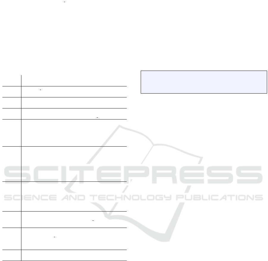
Papyrus modeler). Fig. 2 shows our method. The
latter consists of the following steps:
Step 1. For a State machine from the Moka example
set, we use our code generation tool to generate
code.
Step 2. We simulate the execution of the State ma-
chine by using Moka to extract a sequence Trace
1 of observed traces including executed actions.
Step 3. The sequence (Traces 2) is obtained through
the runtime execution of the code generated in
Step 1.
Step 5. Trace 1 and Trace 2 are compared. The code
is semantic-conformant if Traces 1 and Traces 2
are the same (Blech and Glesner, 2005).
The PSSM test suite consists of 66 test cases for
different state macchine element types. The results
are promising: our tool passes 62/66 tests including:
behavior (5/6), choice (3/3), deferred events (6/6), en-
tering (5/5), exiting (4/5), entry(5/5), exit (3/3), event
(9/9), final state (1/1), fork (2/2), join (2/2), transition
(11/14), terminate (3/3), others (2/2). In fact, our tool
fails with some tests containing transitions (1) from
an entry point to an exit point or (2) from an entry
point/exit point to itself. This is, as our observation,
rarely used in practice because of the contradictory
semantics of entry points and exit points as previously
discussed.
The results of this evaluation are not enough to
prove that our pattern and tooling support preserves
the UML State Machine execution properties but are
a good hint that runtime execution of generated code
is semantically correct (for all but the case identified
above).
MODELSWARD 2017 - 5th International Conference on Model-Driven Engineering and Software Development
214
State machine
Code
Traces 1
Traces 2
Runtime execution
MOKA
Code
generation
1
Trace
comparison
4
Simulation
2
Execution
3
Figure 2: Semantic conformance evaluation methodology.
This evaluation methodology has the limitation
that it is dependent on PSSM. Currently, for event
support, PSSM only specifies signal events. For
pseudo-states, histories are not supported. Thus, our
evaluation result is limited to the current specification
of PSSM.
Threats to Validity: Operation behaviors in PSSM
are defined by activities while our prototype requires
fine-grained behavior as blocks of code embedded
into models. Therefore, an internal threat is that we
manually re-create these tests and convert activities
into programming language code.
6.2 Benchmarks
In this section, we present the results obtained through
the experiments on some efficiency aspects of gener-
ated code to answer the following question.
Research Question 2: Runtime performance and
memory usage are undoubtedly critical in real-time
and embedded systems. Particularly, in event-driven
systems, the performance is measured by event pro-
cessing speed. Are the performance and memory us-
age of code generated by our tool comparable to ex-
isting approaches?
Two state machine examples are obtained by the pre-
ferred benchmark used by the Boost C++ libraries
(Boost Library, 2016a) in (Jusiak, 2016). One simple
example only consists of atomic states and the other
both atomic and composite states.
We compared our tool with tools such as Sinela-
bore (which generates efficient code for Magic Draw
(Magic, 2016), Enterprise Architect (SparxSysems,
2016)), Quantum Modeling (QM) (Quantum Leaps,
2016) (which generates code for event-driven active
object frameworks (Lavender and Schmidt, 1996)),
Boost Statechart (Boost Library, 2016d), Meta State
Machine (MSM) (Boost Library, 2016b), C++ 14
MSM-Lite (Jusiak, 2016), and functional program-
ming like-EUML(Boost Library, 2016c).
We used a Ubuntu virtual machine 64 bit hosted
by a Windows 7 machine. For each tool, we created
two applications corresponding to the two examples,
generated C++ code and compiled it in two modes:
normal (N), by default GCC compiler; and optimal
(O) with GCC optimization options -O2 -s. 11 mil-
lions of events are generated and processed by the
0
100
200
300
400
500
600
700
Min Outlier Max Outlier
Simple benchmark
Composite benchmark
execution time
(ms)
(ms)
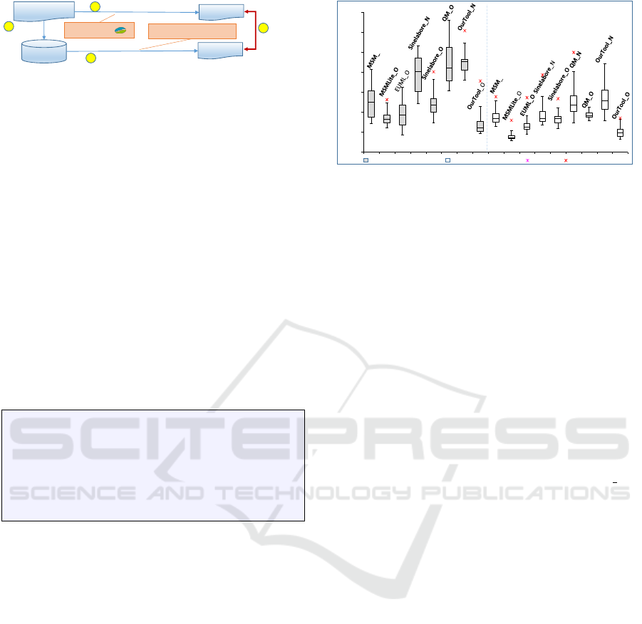
Figure 3: Event processing speed for the benchmarks.
simple example and more than 4 millions for the com-
posite example. Processing time is measured for each
case.
6.2.1 Performance
Fig. 3 shows the event processing performance of
the approaches for the two benchmarks. In the nor-
mal compilation mode ( postfix N), Boost Statechart,
MSM, MSMLite, EUML are quite slow and not dis-
played in the box-plot.
In both of the simple and composite benchmarks,
in optimization mode (postfix O) MSMLite and our
tool run faster than the others in the scope of the ex-
periment. The figure also shows that the optimization
of GCC is significant. In normal mode only the per-
formance of Sinelabore, QM, and our tool is accept-
able. The event processing speed of MSM, MSM Lite
and EUML is too slow without GCC optimizations.
6.2.2 Memory Usage
Table 2 shows the executable size for the exam-
ples compiled in two modes. Without optimiza-
tion, Sinelabore generates the smallest executable size
while our approach takes the second place. In GCC
optimization mode, MSMLite, Sinelabore and our ap-
proach require less static memory than the others.
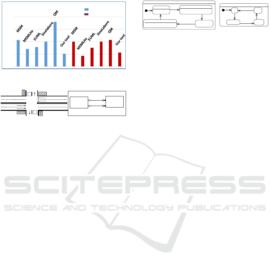
Let’s look closer at the event processing perfor-
mance in optimization mode in terms of time medi-
ans. Fig. 4 shows the figures of the two benchmarks,
relative to the performance of Sinelabore (normalized
to 100%). For the simple (blue) benchmark, our ap-
proach (51.3%) is the fastest. For the composite (red)
benchmark, with the support of C++14, the perfor-
mance in MSMLite (42.7%) is the fastest and ours is
the second.
For runtime memory consumption, we use the
Valgrind Massif profiler (Valgrind, 2016; Nethercote
and Seward, 2007) to measure memory usage. Ta-
ble 3 shows the memory consumption measurements
including stack and heap usage for the composite ex-
ample. Compared to others, code generated by our
Complete Code Generation from UML State Machine
215
106,8
70,7
78,6
100
179,9
51,3
100
42,7
75,5
100
107,1
56,4
0
50
100
150
200
%
Simple benchmark
Composite benchmark
Performance comparison in optimization mode
Figure 4: Event processing performance in optimization
mode.
C
C
Highway
Highway
Farmway
Farmway
Intersection
TrafficLight
+ highway
1
+ farmroad
1
Figure 5: Traffic Light Controller (left) and its class dia-
gram (right).
approach requires a slight overhead with regard to
runtime memory usage (0.35KB). This is predictable
since the major part of the overhead is used for C++
multi-threading using POSIX Threads and resource
control using POSIX Mutex and Condition. However,
the overhead is small and acceptable (0.35KB).
7 TRAFFIC LIGHT
CONTROLLER SIMULATION
In order to assess the usability and practicality of us-
ing UML State Machines and events, we applied our
tool to a simplified Traffic Light Controller (TLC)
system as a case study, which is extracted from (Katz
and Borriello, 2005).
TLC controls an intersection of a busy highway
and a little-used farm-way as in Fig. 5. Detectors
are placed along a farmroad to raise the signal C as
long as a vehicle is waiting to cross the highway. The
highway lights remains green as long as no vehicle
is detected on the farmroad. Otherwise, the highway
lights should change from yellow to red, allowing the
farmroad lights to become green. The farmroad lights
stay green only as long as a vehicle is detected on the
farmroad and never longer than a set interval to allow
the traffic to flow along the highway. If no vehicle
or timeout expired, the farmroad lights change from
green to yellow to red, allowing the highway lights to
return to green. Even if vehicles are waiting to cross
the highway, the highway should remain green for a
set interval.
The object-oriented class diagram follows the de-
sign in Yasmine (Yasmine, 2016), which is a C++11
IntersectionStateMachine
HighwayOpen
SwitchingHighwayToFarmroad
SwitchingFarmroadToHighway
FarmwayOpen
Initial1
TrafficLightStateMachine
Initial1
Red
Red_Yellow
Yellow
Green
OnRed_Yellow
OnGreen
OnYellow
OnRed
Figure 6: State machines for describing the behavior of In-
tersection (left) and TrafficLight (right).
state machine framework, and is shown in Fig. 5
(right). The behavior of each class is described by a
state machine. The state machines of Intersection and
TrafficLight are shown in Fig. 6 (left and right, respec-
tively). All of the states of IntersectionStateMachine,
except FarmwayOpen, are composite. The details of
SwitchingHighwayToFarmroad and SwitchingFarm-
roadToHighway are actually shown on the yasmine
site (Yasmine, 2016).
The conditions for switching from the state High-
wayOpen to SwitchingHighwayToFarmroad are: (1) a
minimum time for the highway open is elapsed; and
(2) the sensors emit a signal.
To show the usability and practicality of UML
events, two alternative designs can be specified by us-
ing time events and change events. Fig. 7 (a) and
(b) show the alternates, respectively. The first design
in 7 (a) uses a time event, which triggers the transi-
tion from WaitingForHighwayMinimum to Minimum-
TimeElapsed, and a signal event deferred by the Wait-
ingForHighwayMinimum state. When HighwayOpen
becomes active, its active sub-state remains Waiting-
ForHighwayMinimum as long as the minimum time.
If a signal C is fired from the detector, a signal event
DetectorOn is sent to the state machine. The event
is, however, not immediately processed but delayed
by until the active sub-state becomes MinimumTimeE-
lapsed in case the time event is fired. The signal event
is then processed to finish the execution of Highway-
Open and activate the farmway.
The other design utilizes a change event instead of
deferred events for switching from WaitForPrecondi-
tions to a final state. Two flags timeFlag and detect-
Flag are used. The WaitForPreconditions state has
two internal transitions. One is triggered by a signal
event associated with the signal C and calls a transi-
tion effect to update detectFlag to true. The other one
triggered by a time event sets timeFlag to true. The
expression associated with the change event updates
from false to true once two flags timeFlag and detect-
Flag are set to true. The periodic evaluation time is
configured as 10ms.
For simulation of TLC, we reuse the detector class
developed in (Yasmine, 2016) to automatically gener-
ate DetectorOn/DetectorOff signals.
The support of UML events (change events and
time events) and deferred events does not only pro-
MODELSWARD 2017 - 5th International Conference on Model-Driven Engineering and Software Development
216
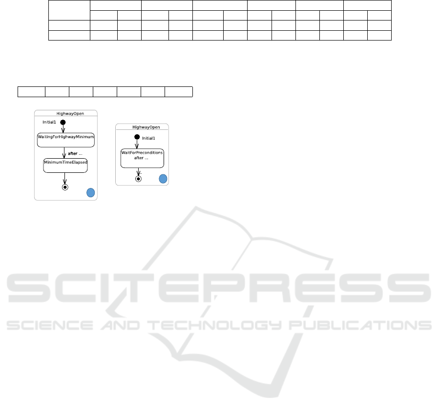
Table 2: Executable size in KB.
Test
MSM MSM-Lite EUML Sinelabore QM Our tool
N O N O N O N O N O N O
Simple 414,6 22,9 107,3 10,6 2339 67,9 16,5 10,6 22,6 16,6 21,5 10,6
Composite 837,4 31,1 159,2 10,9 4304,8 92,5 16,6 10,6 23,4 21,5 21,6 10,6
Table 3: Runtime memory consumption in KB. Columns
from left to right are SC, MSM, MSM-Lite, EUML, Sinela-
bore, QM, and Our tool, respectively.
76.03 75.5 75.8 75.5 75.8 75.7 76.38
DetectorOn
f1
a
DetectorOn
f1
b
Figure 7: Alternative state machine designs for the High-
wayOpen state.
vide designers more options to specify but also sim-
plify system behaviors. It can also reduce the num-
ber of states. For example, the numbers of sub-states
of HighwayOpen with the use of deferred events and
change events are two and one, respectively, while
Yasmine requires three states. However, deferred
events might make the design more difficult to under-
stand because of its specialized semantics.
8 RELATED WORK
Code generation from state machines has received a
lot of attention in automated software development.
This section mentions some existing code genera-
tion patterns and how our approach differs. A sys-
tematic review of several proposals is presented in
(Dom
´
ınguez et al., 2012).
Switch/if is the most intuitive technique for imple-
menting a ”flat” state machine. It either uses a scalar
variable (Booch et al., 1998) and a method for each
event, or using two variables as the active state and
the incoming event used as the discriminators of an
outer switch statement to select between states and
an inner one/if statement, respectively. The state ta-
ble approach (Douglass, 1999) uses one dimension
for representing states and the other one for all possi-
ble events. These approaches require a transformation
from hierarchical to flatten state machines. However,
these approaches are hardly applied to state machines
containing pseudo states such as deep history or join/-
fork.
The object-oriented state pattern (Shalyto and
Shamgunov, 2006; Douglass, 1999) transforms a state
into a class and an event into a method. Events are
processed by delegating from the class containing the
state machine to its sub-state classes. Separation of
states in classes makes the code more readable and
maintainable. Unfortunately, this technique only sup-
ports flat state machines. This pattern is extended in
(Niaz et al., 2004) to support hierarchical state ma-
chines. Recently, a double-dispatch (DD) pattern pre-
sented in (Spinke, 2013) extends (Niaz et al., 2004)
to support maintainability by representing states and
events as classes, and transitions as methods. How-
ever, as the results shown in (Spinke, 2013), these pat-
terns require much memory because of an explosion
of the number of classes and use dynamic memory al-
location, which is not preferred in embedded systems.
It is worth noting that none of these approaches pro-
vides implementation for all of state machine pseudo
states as well as events.
Tools such as (SparxSystems, 2016; IBM, 2016b)
apply different patterns to generate code. However,
as mentioned in Section 1, true concurrency, some
pseudo-states, and UML events are not supported.
FXU (Pilitowski and Derezi
˜
nska, 2007) is the most
complete tool but generated code is heavily dependent
on their own library and C# is generated.
Umple (Badreddin et al., 2014b) is a textual UML
programming language, which supports code gener-
ation for different languages such as C++ and Java
from state machines. However, Umple does not sup-
port pseudo states such as fork, join, junction, and
deep history, and local transitions. Furthermore, only
call events and time events are specified in Umple.
Our approach combines the classical switch/if pat-
tern, to produce small footprint, and the pattern in
(Niaz et al., 2004), to preserve state hierarchy. Fur-
thermore, we define pattern to transform all of USM
concepts including states, pseudo states, transitions,
and events. Therefore, users are flexible to create
there USM conforming to UML without restrictions.
9 CONCLUSION
We presented an approach whose objective is to pro-
vide a complete, efficient, and UML-compliant code
generation from UML State Machines with full fea-
Complete Code Generation from UML State Machine
217

tures. The design for concurrency of generated code
is based on multi-thread of POSIX. The code gener-
ation pattern extends the IF-ELSE/SWITCH patterns
and uses a hierarchical structure to preserve the state
machine hierarchy.
We implemented our pattern as part of the Papyrus
modeling tool. We evaluated our tool by conducting
experiments on the semantic-conformance and effi-
ciency of generated code. The conformance is tested
under PSSM: 62 of 66 tests passed. These results are
a good hint that our tool preserves the UML State
Machine semantics during code generation. For ef-
ficiency, we used the benchmark defined by the Boost
library to compare code generated by our tool to other
approaches. The results showed that our tool pro-
duces efficient code that runs fast in event processing
speed and is small in executable size.
Code produced by our tool, however, consumes
slightly more memory than that of the others at run-
time. In future work, we will fix this issue by mak-
ing multi-thread part of generated code more concise.
Furthermore, we will use the pattern to support Java
code generation from UML State Machines.
REFERENCES
Badreddin, O., Lethbridge, T. C., Forward, A., Elaasar, M.,
Aljamaan, H., and Garzon, M. A. (2014a). Enhanced
code generation from uml composite state machines.
In Model-Driven Engineering and Software Develop-
ment (MODELSWARD), 2014 2nd International Con-
ference on, pages 235–245. IEEE.
Badreddin, O., Lethbridge, T. C., Forward, A., Elasaar, M.,
and Aljamaan, H. (2014b). Enhanced Code Genera-
tion from UML Composite State Machines. Model-
sward 2014, pages 1–11.
Balser, M., B
¨
aumler, S., Knapp, A., Reif, W., and Thums,
A. (2004). Interactive verification of uml state ma-
chines. In International Conference on Formal Engi-
neering Methods, pages 434–448. Springer.
Blech, J. O. and Glesner, S. (2005). Formal verification of
java code generation from uml models. In . . . of the
3rd International Fujaba Days, pages 49–56.
Booch, G., Rumbaugh, J., and Jacobson, I. (1998). The
Unified Modeling Language User Guide, volume 3.
Boost Library (2016a). Boost C++. http://www.boost.org/.
[Online; accessed 04-July-2016].
Boost Library (2016b). Meta State Machine. http://
www.boost.org/doc/libs/1 59 0 b1/libs/msm/doc/
HTML/index.html. [Online; accessed 04-July-2016].
Boost Library (2016c). State Machine Benchmark.
http://www.boost.org/doc/libs/1 61 0/libs/msm/doc/
HTML/ch03s04.html.
Boost Library (2016d). The Boost Statechart Library. [On-
line; accessed 04-July-2016].
Butenhof, D. R. (1997). Programming with POSIX threads.
Addison-Wesley Professional.
Charfi, A., Mraidha, C., and Boulet, P. (2012).
An optimized compilation of uml state machines.
In 2012 IEEE 15th International Symposium on
Object/Component/Service-Oriented Real-Time Dis-
tributed Computing, pages 172–179.
Dom
´
ınguez, E., P
´
erez, B., Rubio, A. L., and Zapata, M. A.
(2012). A systematic review of code generation pro-
posals from state machine specifications.
Douglass, B. P. (1999). Real-time UML : developing effi-
cient objects for embedded systems.
Forward, A., Lethbridge, T. C., and Badreddin, O. (2010).
Perceptions of software modeling: A survey of soft-
ware practitioners. In in 5th Workshop from Code
Centric to Model Centric: Evaluating the Effec-
tiveness of MDD (C2M: EEMDD), 2010. Available:
http://www. esi. es/modelplex/c2m/papers. php. Cite-
seer.
G
´
erard, S., Dumoulin, C., Tessier, P., and Selic, B. (2010).
19 papyrus: A uml2 tool for domain-specific language
modeling. In Model-Based Engineering of Embedded
Real-Time Systems, pages 361–368. Springer.
IBM (2016a). IBM Rhapshody and UML differ-
ences. http://www-01.ibm.com/support/docview.wss?
uid=swg27040251. [Online; accessed 04-July-2016].
IBM (2016b). Ibm Rhapsody. [Online; accessed 04-July-
2016].
Jusiak, K. (2016). State Machine Benchmark. https://
github.com/boost-experimental. [Online; accessed
20-Oct-2016].
Katz, R. H. and Borriello, G. (2005). Contemporary logic
design.
Knapp, A. (2004). Semantics of UML State Machines.
Lavender, R. G. and Schmidt, D. C. (1996). Active Object.
Context, pages 1–12.
LISE. Papyrus Software Designer. https://wiki.eclipse.org/
Papyrus Software Designer.
Magic, N. (2016). Magic Draw. https://
www.nomagic.com/products/magicdraw.html. [On-
line; accessed 14-Mar-2016].
Mussbacher, G., Amyot, D., Breu, R., Bruel, J.-m., Cheng,
B. H. C., Collet, P., Combemale, B., France, R. B.,
Heldal, R., Hill, J., Kienzle, J., and Sch
¨
ottle, M.
(2014). The Relevance of Model-Driven Engineer-
ing Thirty Years from Now. ACM/IEEE 17th Interna-
tional Conference on Model Driven Engineering Lan-
guages and Systems (MODELS), pages 183–200.
Nethercote, N. and Seward, J. (2007). Valgrind: a frame-
work for heavyweight dynamic binary instrumenta-
tion. In ACM Sigplan notices, volume 42, pages 89–
100. ACM.
Niaz, I. A., Tanaka, J., and others (2004). Mapping UML
statecharts to java code. In IASTED Conf. on Software
Engineering, pages 111–116.
OMG (2016). Precise Semantics of UML State Machines
(PSSM) Revised Submission. [Revised Submission,
ad/16-11-01].
Papyrus (2016). Moka Model Execution. https://wiki.
eclipse.org/Papyrus/UserGuide/ModelExecution.
[Online; accessed 01-Nov-2016].
MODELSWARD 2017 - 5th International Conference on Model-Driven Engineering and Software Development
218

Pilitowski, R. and Derezi
˜
nska, A. (2007). Code Genera-
tion and Execution Framework for UML 2.0 Classes
and State Machines, pages 421–427. Springer Nether-
lands, Dordrecht.
Quantum Leaps (2016). Quantum Modeling. http://
www.state-machine.com/qm/. [Online; accessed 14-
May-2016].
Shalyto, A. and Shamgunov, N. (2006). State machine de-
sign pattern. Proc. of the 4th International Conference
on.NET Technologies.
SparxSysems (2016). Enterprise Architect. http://
www.sparxsystems.com/products/ea/. [Online; ac-
cessed 14-Mar-2016].
SparxSystems (2016). Enterprise Architect. http://
www.sparxsystems.eu/start/home/. [Online; accessed
20-Nov-2016].
Specification, O. M. G. A. and Bars, C. (2007). OMG Uni-
fied Modeling Language ( OMG UML ). Language,
(November):1 – 212.
Spinke, V. (2013). An object-oriented implementation of
concurrent and hierarchical state machines. Informa-
tion and Software Technology, 55(10):1726–1740.
Valgrind (2016). Valgrind Massif. http://valgrind.org/docs/
manual/ms-manual.html. [Online; accessed 20-Nov-
2016].
Whittle, J., Hutchinson, J., and Rouncefield, M. (2014).
Model-driven engineering practices in industry: So-
cial, organizational and managerial factors that lead to
success or failure. Science of Computer Programming,
89:144–161.
Yasmine (2016). The classic farmroad example. http://
yasmine.seadex.de/yasmine.html. [Online; accessed
20-Nov-2016].
Complete Code Generation from UML State Machine
219
