
A Technique to Architect Real-time Embedded Systems with SysML and
UML through Multiple Views
Quelita A. D. S. Ribeiro
1
, Fab
´
ıola G. C. Ribeiro
2
and Michel S. Soares
1
1
Department of Computing, Federal University of Sergipe, Sao Cristov
˜
ao, Sergipe, Brazil
2
Federal Institute Goiano, Catal
˜
ao, Brazil
Keywords:
Software Architecture, Automotive Embedded System, Real-time Systems, SysML, UML.
Abstract:
Describing the architecture of real-time systems by means of semi-formal languages has been often considered
in the literature. However, the most common approach is to propose multiple modeling languages in an
orthogonal manner, i.e., the models are used in separate phases, in a totally independent way. This situation is
not always possible, and the assumption in this paper is to propose a technique in which diagrams from two
modeling languages are integrated. In this paper, UML and SysML are used together. Thus, the proposed
technique is capable of modeling both software and system architectural elements, by satisfying the following
modeling criteria: support to model components and connectors, both graphical and textual syntax, modeling
non-functional requirements, design of structural view of software using UML classes, represent hardware
elements in the architecture, and to describe traceability between requirements. A case study on a real-time
automotive embedded system is presented to illustrate the technique.
1 INTRODUCTION
As complexity of electronic systems and embedded
applications increase, there is a continuous need for
more abstract representations of such systems. Mo-
deling the architecture of systems is a challenging
task as these systems are not only huge in magni-
tude but are also significantly diverse (Khan et al.,
2015). Design of complex systems involves archi-
tectural specification of software, including software
structure and organization, synchronization between
tasks and processes, physical distribution of elements,
composition of design elements, selection among de-
sign alternatives and considering quality characteris-
tics such as scalability and performance. Software
architecture is essential during all software develop-
ment phases, given that the architecture description
affects the success of a project and helps stakeholders
to understand the software to be developed (Gardazi
et al., 2009).
Embedded systems are dedicated computational
systems, composed by hardware and software com-
ponents. When the correctness of these systems de-
pends not only on their functional behavior, but also
on their timing behavior, they are classified as real-
time embedded systems (Marques et al., 2014). UML,
mainly through Class, Sequence, and Activity dia-
grams, is the most popular language for software mo-
deling (Reggio et al., 2015). However, UML support
for embedded systems presents many challenges, in-
cluding the lack of standard formal semantics, many
semantic variation points, and the variety of diagrams,
which may contain inconsistencies. UML expressi-
vity is considered not completely satisfactory for this
domain (Jouault and Delatour, 2014).
These restrictions have motivated the investigation
of strategies to successfully support the development
of complex systems. Therefore, the Systems Mo-
deling Language (SysML) offers additional resources
to UML, including requirements and constraints mo-
deling (Marques et al., 2014). SysML also has featu-
res to support the specification of diverse structural,
behavioral and temporal aspects of complex embed-
ded systems (Khan et al., 2015).
This work proposes a technique to use SysML as
a modeling language in a real-time embedded system
combined with UML. A qualitative analysis presents
the advantages of this approach when comparing to
other similar proposals published in the literature.
Ribeiro, Q., Ribeiro, F. and Soares, M.
A Technique to Architect Real-time Embedded Systems with SysML and UML through Multiple Views.
DOI: 10.5220/0006294802870294
In Proceedings of the 19th International Conference on Enterprise Information Systems (ICEIS 2017) - Volume 2, pages 287-294
ISBN: 978-989-758-248-6
Copyright © 2017 by SCITEPRESS – Science and Technology Publications, Lda. All rights reserved
287
2 BASICS ON SysML
SysML was developed by the Object Management
Group (OMG) and International Council on Systems
Engineering (INCOSE) with the objective of develo-
ping a unified general purpose language for modeling
systems (SysML, 2015). SysML diagrams used in
this paper are briefly as follows.
SysML Requirements diagram provides a mo-
deling construct for text-based requirements (SysML,
2015). It models and describes several system requi-
rements such as non-functional requirements, as well
as showing the various types of relationships between
different requirements, and other model elements that
satisfy or verify them (SysML, 2015). SysML Requi-
rements diagram can display requirements, packages,
other classifiers, test cases, rationale and also relati-
onships between requirements and also their relati-
onships to other diagrams (SysML, 2015) (Soares and
Vrancken, ).
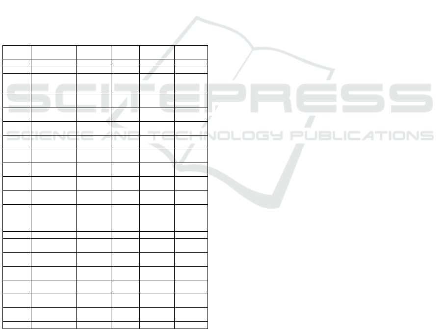
Table 1: SysML Airbag Requirements Table.
id name type
derived
Req
derived-
From Req
contain-
ment Req
FR8 Movement functional FR9 - -
FR7 Angle functional FR9 - -
FR9
Activate
airbag
functional -
NFR02,
FR8,
FR7
-
FR1
Get speed
value
functional RR2 - -
FR4
Calculate
weight
functional FR3 - -
FR2
Evaluate
speed
functional
FR3,
NFR06
FR1 -
FR3
Recognize
slowdown
functional
FR5,
FR4
FR2,
NFR04
-
FR5
Calculate
collision angle
functional FR10 FR3 FR6
FR6
Recognize
angle
functional - -
RF7,
RF8
FR11
Get airbag
sensor signal
functional FR10 - -
FR12
Recognize
act status
functional FR10 - -
FR10
Schedule
requests
functional -
FR12,
FR11,
FR13,
FR5
FR15
FR14 Notify status functional - FR13 -
FR13
Evaluate
operation
functional
FR10,
FR14
- -
NFR01 Safety
non-
functional
- - FR1
NFR02 Reliability
non-
functional
FR9 NFR05 -
NFR04 Availability
non-
functional
FR3 - -
NFR05 Rule
non-
functional
NFR02 - -
NFR06 Integrity
non-
functional
- FR2 -
FR15 Run requests functional - - -
SysML Blocks are modular units of system des-
criptions in SysML. SysML Blocks and their relati-
onships are visualized by the SysML Block Definition
diagram and their internal structure by the SysML In-
ternal Block diagram. SysML Block Definition dia-
gram (BDD from now on) is based on the UML Class
diagram, but with restrictions and extensions defined
for SysML. This diagram defines the structure of the
system by blocks, the operations that can be execu-
ted by the block, as well as the relationships between
blocks, such as associations, generalizations and de-
pendencies (SysML, 2006). Blocks describe speci-
fic types of components, connections between com-
ponents, and the way these elements are combined
to define the complete system. SysML Blocks can
be used throughout all phases of system specification
and design. The SysML Blocks diagram can model
either the logical or physical decomposition of a sy-
stem, as well as software, hardware, or human ele-
ments (SysML, 2015).
The definition of a block in SysML can be furt-
her detailed by specifying its parts: ports, specifying
its interaction points, and connectors, specifying the
connections among its parts and ports. Deployment of
software to hardware, interaction overview and com-
munication can be represented in the SysML Inter-
nal Block diagram. SysML Activity diagram is used
to describe the control flow, and inputs and outputs
flow between the actions of a system. Within UML
Activities, control can only enable actions to start.
This is accomplished by providing a model library
with a type for control values that are treated like data
(SysML, 2015).
3 ARCHITECTURE OF AN
AUTOMOTIVE EMBEDDED
SYSTEM WITH SysML
Automotive embedded systems can be divided among
“vehicle-centric” functional domains, such as power
train control, chassis control, and active or passive sa-
fety systems, and “passenger centric” functional dom-
ains where multimedia/telematics, body/comfort, and
human-machine interface can be identified (Zurawski,
2009). The body domain contains functions embed-
ded in a vehicle that are related to the wipers, lights,
doors, windows, seats, airbag, and mirrors. These
functions have been controlled more and more by
software-based systems in past years. In general, they
are not subject to stringent performance constraints
and, from a safety standpoint, they do not represent a
critical part of the system. However, there are certain
functions, like an advanced system whose aim is to
control access to the vehicle for security, that have to
respect hard real-time constraints (Zurawski, 2009).
ICEIS 2017 - 19th International Conference on Enterprise Information Systems
288
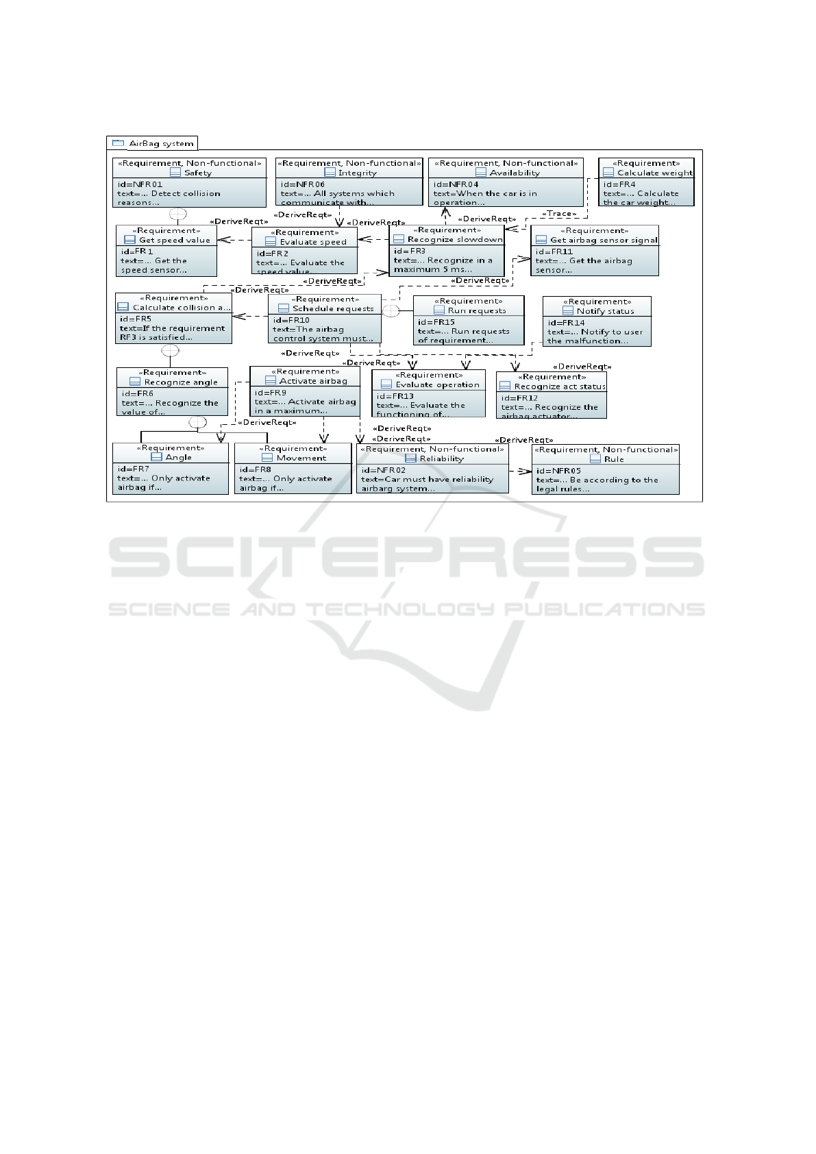
Figure 1: SysML Requirements diagram.
3.1 Airbag Control Example
The Airbag control system is composed by controllers
that diagnose collisions through internal sensors, ex-
ternal sensors, through actuators for airbag activation
by the diagnosis module. Airbag control is able to
evaluate the operation, when the vehicle is turned on.
In this section, we first present the example that we
use in our modeling approach followed by description
of its textual requirements, the SysML Requirements
diagram (Figure 1), and SysML Table (Table 1).
Airbag is a safety item able to soften the impact
of a possible collision and protect the lives of passen-
gers. Coupled with the safety belt, airbag protects the
driver and any passenger against the effects of a fron-
tal impact on the vehicle. Airbag system is not acti-
vated in side impacts, rear impacts or rollover. It is
activated only if the impact occurs within a maximum
angle of 30 degrees with respect to front movement.
Sensors and actuators are incorporated into the sy-
stem control unit. Sensors recognize a sharp slow-
down, identifying when the speed varies in at least
20 km/h in a short time, as in a collision. Actuator
aims to determine the moment of airbag triggering.
Control unit sends an electrical signal to the igniter
that is responsible for inflating the airbag. Within the
igniter, substances such as nitrates and ammonia gua-
nidine react and explode instantly. Chemical reaction
generates enough nitrogen to fill up the bag in just 30
milliseconds. Airbag begins to empty on impact with
the body. Airbag contains a chemical generator gas in
a solid state. This gas is stored in a metal chamber.
When the control unit receives the sensor signal, an
electric current is applied to the bag.
3.2 Set of Airbag Requirements
In this example, according to the characteristics lis-
ted before, and results of the detailed domain analysis
we conducted, the main requirements for modeling
of such complex system are (NFR stands for Non-
Functional Requirements, and FR stands for Functi-
onal Requirements):
NFR01: The airbag control system must detect col-
lision reasons.
NFR02: The car must have reliability airbag system
- tests must guarantee low rate (0.10%) of soft-
ware failures.
NFR03: The airbag control system must use security
protocols in data transmission.
NFR04: When the car is in operation, the airbag con-
trol system must be available 99,6 % of time.
NFR05: The airbag control system must be designed
according to legal rules (omitted for review).
A Technique to Architect Real-time Embedded Systems with SysML and UML through Multiple Views
289
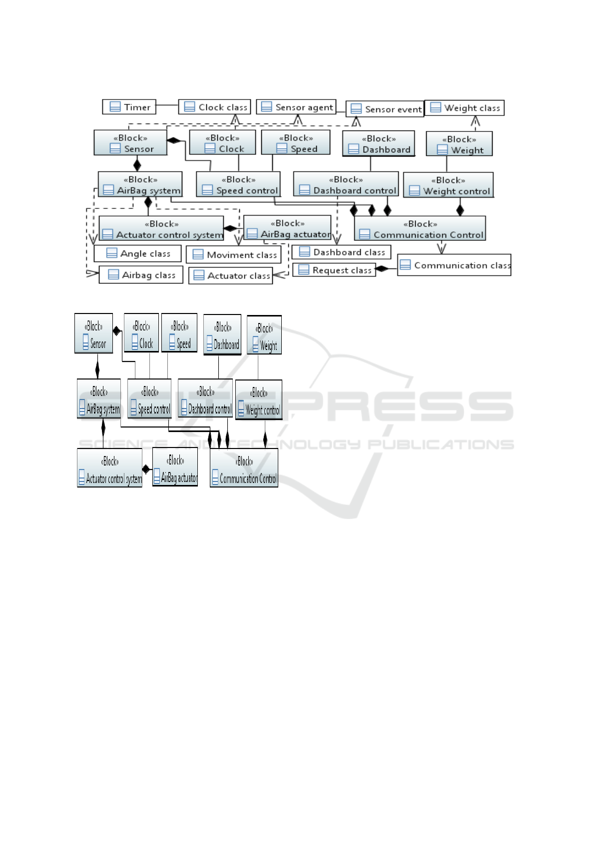
Figure 3: UML Class diagram combined with SysML BDD diagram.
Figure 2: SysML BDD diagram.
NFR06: The airbag control system must be righ-
teous, all systems which communicate with the
airbag system must be identified, monitored and
blocked from changing data, unless they are aut-
horized.
FR1: The airbag control system must get the speed
sensor signal of car every 15 ms.
FR2: The airbag control system must evaluate the
speed value received from sensor every 15 ms.
FR3: The airbag control system must recognize in
a maximum of 5 ms an abrupt deceleration of at
least 20 km/h.
FR4: When the car is in operation, the airbag cont-
rol system must calculate the car weight plus the
passenger weight in a maximum of 5 s.
FR5: If the requirement RF3 is satisfied, then the
airbag control system must calculate the collision
impact angle in exactly 5 ms.
FR6: The airbag control system must recognize the
value of collision impact angle in a maximum of
5 ms.
FR7: The airbag control system must only activate
the airbags if the impact angle is lower than 30
degrees.
FR8: The airbag control system must only activate
the airbags if the collision impact is at frontal mo-
vement.
FR9: The airbag control system must activate the
airbags in a maximum of 15 ms after collision im-
pact.
FR10: The airbag control system must schedule si-
multaneous requests every 15 ms.
FR11: The airbag control system must get the airbag
sensor signal every 15 ms.
FR12: The airbag control system must recognize the
airbag actuator status every 5 ms.
FR13: The airbag control system must evaluate the
functioning of all components every 15 ms.
FR14: The airbag control system must notify to user
the malfunction of any light component (with a
light on the dashboard) in a maximum of 50 ms.
FR15: The airbag control system must run requests
of requirement RF10 every 10 ms.
ICEIS 2017 - 19th International Conference on Enterprise Information Systems
290
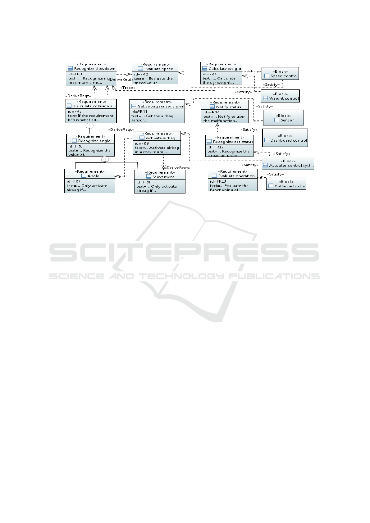
Figure 4: SysML Requirements diagram combined with Sysml BDD diagram.
3.3 Airbag Requirements (Diagram and
Table)
The SysML Requirements diagram of the airbag con-
trol system is depicted in Fig. 1. SysML also al-
lows the representation of requirements, their proper-
ties and relationships in a tabular format. Normally,
table fields’ are the requirement’s ID, name and type.
In our proposal, we added fields “derived Req”, “deri-
vedFrom Req”, “containment Req” (this relationship
represents hierarchy) in Table 1.
Requirements diagram refers to the practice of de-
composing a complex requirement into simpler, sin-
gle requirements. In the airbag system, the relations-
hips between requirements were mostly described by
hhDeriveReqii and containment (represented by ⊕–
symbol).
The Derive relationship relates a derived require-
ment to its source requirement. This typically invol-
ves analysis to determine the multiple derived requi-
rements that support a source requirement. The de-
rived requirements generally correspond to require-
ments at the next level of the system hierarchy. Con-
tainment relationship specifies hierarchies between
requirements, its use precludes reusing requirements
in different contexts since a given model element can
only exist in one containment (SysML, 2015).
With the goal to model the non-functional require-
ments concept, we have also introduced a stereotype
named hhNon-functionalii. This stereotype allows to
distinguish with others, and facilitates to understand
the architecture.
3.4 Airbag BDD Diagram
In our example, we use BDD to model components
involved in the airbag system. Specified functions are
implemented for secure communications with other
components, and with local sensors/actuators. SysML
BDD diagram is depicted in Fig. 2. Airbag functions
often involve many communications between each ot-
her, and consequently, have a complex distributed ar-
chitecture. These functions are implemented by a
main electronic control unit (ECU) named communi-
cation control, which supports the reception of reque-
sts while the other units perform their own requested
actions.
In the Airbag example, 12 related blocks are de-
fined. Relationships between blocks are represented
by composition associations. Composition instance is
synchronous, because the “Clock” Block controls the
time function. If an instance is destroyed, ending exe-
cution, the other executions are also terminated. With
SysML BDD diagram, hardware, data, and procedu-
res can be modeled. The representation of system ar-
chitecture can be made by means of blocks, without
focusing only on the software structure of each sy-
stem element, but also on the general structure, in-
cluding parts of each block, constraints and proper-
ties not necessarily related to software. In addition,
SysML Blocks are candidates to be refined into one
or more UML classes (See Fig. 6) during the soft-
ware design and implementation phases.
A Technique to Architect Real-time Embedded Systems with SysML and UML through Multiple Views
291
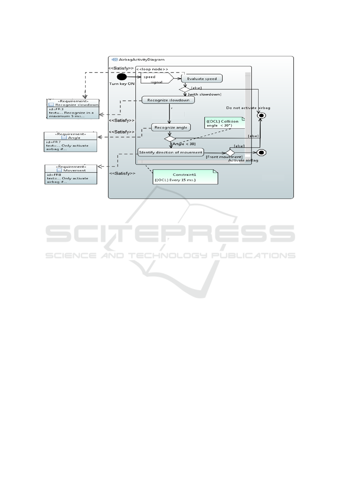
Figure 5: SysML Requirements diagram and SysML Activity diagram.
3.5 SysML Activity diagram
We represent the main Activity diagram of the air-
bag control system in Fig. 5. Our diagram introduces
the activity to activate the airbag. We modeled initial
and final activity, decisions node that choose between
outgoing flows, iterative loop with hhloop nodeii, and
constraints for time and angle.
4 PROPOSED TECHNIQUE
COMBINING SYSML AND UML
Our approach concentrates on models designed along
three architectural views: requirements, structure, and
behavior. We use SysML Requirements diagram and
Table, illustrated in Fig. 1 and Table 1 for expressing
requirements. We model the system structure using
SysML BDD diagram, illustrated in Fig. 2. Finally,
we use SysML Activity diagram, illustrated in Fig.
5, for capturing behaviors. Our technique is applied
to relate the models and to analyze the impact of re-
quirements in both software and system design of an
embedded system.
In Table 1, it is possible to analyze how a change
in one requirement will impact in the others (derived
Req, derived from Req, and containment Req). To
perceive this impact, it is necessary to comprehend
the relationship of requirements.
Derive relationship relates a derived requirement
to its source requirement. This typically involves
analysis to determine the multiple derived require-
ments that support a source requirement. Derived
requirements generally correspond to requirements
at the next level of the system hierarchy (SysML,
2015). A composite requirement can contain sub-
requirements, which describes a requirements hierar-
chy tree. This relationship enables a complex requi-
rement to be decomposed into its containing child re-
quirements (SysML, 2015).
When SysML Blocks and Requirements are rela-
ted, the design of a system can be analyzed, as shown
in diagram in Fig. 4. This diagram is not complete
due to lack of paper space limit. Thus, it is possible
to identify which requirements are associated with a
particular Block, and to identify which requirement
belongs to which block. Moreover, relationship sa-
tisfy inside this diagram describes how a Block sa-
tisfies one or more Requirements. It represents a de-
pendency relationship between a Requirement and a
Block.
We combine UML Classes with SysML Blocks by
means of the dependency relationship in Fig. 3. De-
pendency does not need to be labeled, because it is
a simple relationship between block and class. The
main reason for this choice, to model components
with SysML Blocks and UML Class, is because this
technique provides a simple way to map systems ele-
ments to software elements. Besides, knowing the
ICEIS 2017 - 19th International Conference on Enterprise Information Systems
292
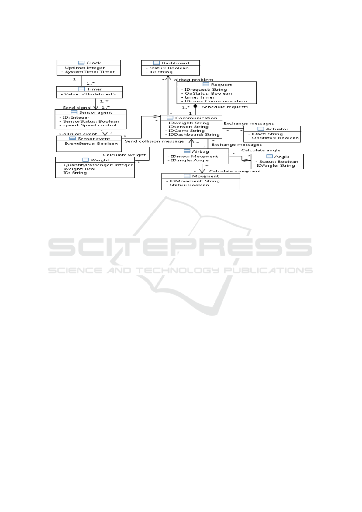
Figure 6: UML Class diagram.
mapping from system elements to software elements
may bring together the work of systems and software
engineers (Melo and Soares, 2014).
By combining SysML Activity diagram with
SysML Requirements diagram, as depicted in Fig. 5,
it is possible to analyze how a change in one requi-
rement will affect the activity developed, what acti-
ons will be satisfied by a requirement, and also which
actions will be affected if it occurs a change in this
requirement.
SysML Requirements diagram allows to map a re-
quirement to other design models, or other diagrams.
Relationships between requirements, and their classi-
fications, are also represented. For instance, when a
requirement is modified, it is possible to trace which
requirements and models are affected, and how they
are going to be affected.
SysML Blocks are mapped into one or more UML
Classes during the software design and implementa-
tion phases. This mapping is a modeling part that
does not have strict rules (Authors reference) (Melo
and Soares, 2014).
5 RELATED WORKS
Recently, the combination of languages with SysML
has been investigated for embedded and complex sy-
stems in order to support a systems design. The
authors of paper (Melo and Soares, 2014) combined
the SysML Block diagram with the UML Class di-
agram to design the structural view of a software-
intensive system architecture. An experiment is pre-
sented in paper (Vogel-Heuser et al., 2014) regarding
UML and SysML on aspects of usability. The in-
tention was to show the increasing of efficiency and
quality of software in the development process. A
model-driven requirement engineering approach for
the embedded software domain is described in (Mar-
ques et al., 2014). The approach is based on UML,
MARTE and SysML notations, which are integrated
to improve requirements specification and traceabi-
lity. Finally, in paper (Khan et al., 2015) a unified
approach is proposed for system design and its ve-
rification based on SysML, MARTE, CCSL and Sys-
temVerilog to help hardware engineers in the verifica-
tion process. Nevertheless, combining three modeling
languages (SysML, MARTE, CCSL) plus a hardware
language (SystemVerilog) can be obscure for engi-
neers, needs additional efforts, time, and cost to ma-
nage the process. In addition, the authors could have
explored more SysML diagrams.
In contrast with other papers, our approach has fo-
cus to combine UML and SysML, a UML profile, in
order to communicate the same project with different
stakeholders involved. Our approach shows tracea-
bility between SysML Requirements, between struc-
tural design with SysML Requirements and SysML
Blocks, with SysML Blocks and UML Classes, and
also describes behavioral design with UML/SysML
Activity diagram and SysML Requirements diagram.
None of these related articles showed all these cha-
racteristics. Some articles focus only on requirements
traceability, others on model synchronization, and so
on. In addition, we present languages with the same
semantics, this aspect is important to facilitate the
A Technique to Architect Real-time Embedded Systems with SysML and UML through Multiple Views
293

process of learning. To the best of our knowledge, we
have only found the works (Vogel-Heuser et al., 2014)
and (Melo and Soares, 2014) that combine SysML
and UML in the last five years. Concerning the com-
bination of languages, the authors show only the con-
cern of finding the correct relationship between UML
and SysML diagrams for a particular focus.
6 CONCLUSION
In the technique proposed in this paper, we combine
SysML with UML for describing the architecture of
embedded systems, with the main purpose of consi-
dering all advantages that both languages combined
have. We present a work motivated by reality (Zu-
rawski, 2009). Descriptions and concepts about air-
bag system came mainly from there.
SysML Requirements diagram and SysML Ta-
bles are recognized as useful in activities of Requi-
rements Engineering by many authors. A SysML
Requirement can appear on other UML/SysML dia-
grams to show its relationship to design. The relati-
onships between requirements can improve the spe-
cification of systems, as they can be used to model,
document and analyze requirements. SysML Requi-
rements diagram support traceability between requi-
rements and modeling of other types of requirements
besides the functional ones. We observe the advan-
tages of the SysML modeling language in Require-
ments Engineering, recognize SysML general charac-
teristics, and expand SysML concepts to model sy-
stem architecture of a real-time embedded system.
Our proposed technique integrates SysML with UML
in order to include SysML with software modeling
elements, such as UML Classes.
In this paper, we describe how we combined two
modeling languages to provide a common modeling
language for specifying embedded systems at diffe-
rent abstraction levels. The Airbag system is consi-
dered as an example inspired by reality. In compari-
son with the other items of body comfort, airbag cont-
rol system was chosen because it has more interaction
with other car’s components, has more defined requi-
rements, activities in real-time, and represents a car
security item. Besides, to the best of our knowledge,
we have not find research related to airbag architec-
ture modeling with SysML or other language.
Our technique uses MOF conformance modeling
languages (SysML and UML) to help engineers and
software architects to communicate and to develop
optimized system solutions. We understand that UML
and SysML are well-known and generally preferred in
software industry because they reduce training costs,
reduce the learning time gap, and have adequate tool
support.
ACKNOWLEDGEMENTS
The authors would like to thank the Brazilian rese-
arch agency CNPq (grant 445500/2014-0) for finan-
cial support.
REFERENCES
Gardazi, S. U. et al. (2009). Survey of Software Architec-
ture Description and Usage in Software Industry of
Pakistan. In International Conference on Emerging
Technologies, pages 395–402.
Jouault, F. and Delatour, J. (2014). Towards Fixing Sket-
chy UML Models by Leveraging Textual Notations:
Application to Real-Time Embedded Systems. In
Proceedings of the 14th International Workshop on
OCL and Textual Modelling co-located with 17th In-
ternational Conference on Model Driven Engineering
Languages and Systems (MODELS 2014), Valencia,
Spain, September 30, 2014., pages 73–82.
Khan, A. M., Mallet, F., and Rashid, M. (2015). Modeling
SystemVerilog Assertions using SysML and CCSL. In
Electronic System Level Synthesis Conference.
Marques, M. R. S., Siegert, E., and Brisolara, L. (2014). In-
tegrating UML, MARTE and SysML to Improve Re-
quirements Specification and Traceability in the Em-
bedded Domain. In 12th IEEE International Confe-
rence on Industrial Informatics (INDIN), pages 176–
181.
Melo, M. d. S. and Soares, M. S. (2014). Model-
driven Structural Design of Software-intensive Sys-
tems Using SysML Blocks and UML Classes. In
Proceedings of the International Conference on En-
terprise Information Systems, volume 2, pages 193–
200.
Reggio, G., Leotta, M., Ricca, F., and Clerissi, D. (2015).
What Are the Used UML Diagram Constructs? A Do-
cument and Tool Analysis Study Covering Activity and
Use Case Diagrams.
Soares, M. S. and Vrancken, J. Model-Driven User Re-
quirements Specification Using SysML. Journal of
Software, 3(6):57–68.
SysML, M. T. (2006). Systems Modeling Language
(SysML) Specification. OMG document: 2006-03-01.
SysML, O. (2015). OMG Systems Modeling Language
(OMG SysML).
Vogel-Heuser, B. et al. (2014). Usability Experiments to
Evaluate UML/SysML-based Model Driven Software
Engineering Notations for Logic Control in Manufac-
turing Automation. Journal of Software Engineering
and Applications, 7(11):943.
Zurawski, R. (2009). Embedded Systems Handbook, 2-
Volume Set. CRC Press, Inc.
ICEIS 2017 - 19th International Conference on Enterprise Information Systems
294
