
Optimal Sizing of Capacitor Banks to Reduce Power Losses
With Accounting of Temperature Dependence of Bare Overhead Conductors
Vladimir Goryunov, Stanislav Girshin, Evgenii Kuznetsov, Aleksandr Bigun,
Elena Petrova and Alexey Lyashkov
Energy Department, Omsk State Technical University, pr. Mira 11, Omsk, Russia
Keywords: Capacitor Banks, Bare Overhead Conductors, Power Losses, Temperature, Thermal Rating, Energy
Efficiency, Optimization, Smart Grids.
Abstract: In carrying out a reactive power compensation it is necessary to select the powers of compensation units for
minimizing the active power losses as well as minimize financial losses of installing the reactive power
compensation units. Thus, there is a multi-factor optimization problem for sizing of reactive power
compensation devices. The paper studied the effect of bare overhead conductors heating to the optimal
choice of measures to reduce electricity losses by the example of reactive power compensation. We describe
two stages in the selection of reactive power compensation devices and their clarification considering the
grid elements temperature. We determine the economic efficiency calculations results of using reactive
power compensation as measures to reduce losses in grids, with and without the grid elements temperature
dependence consideration. We consider the data on the optimal choice of compensating devices and
payback period determination depending on the load, the conductor type and the grid length. The research
results can be applied in the optimization of existing systems and in the design of power supply systems of
enterprises to reduce the active power losses with the minimal cost of compensation units.
1 INTRODUCTION
One of the major problems in the power sector is to
reduce the power losses in grids. The grid comprises
generating, supply mains, distribution mains and
loads. The power loss in the distribution systems
may reach 13% (Isac et al., 2013) resulting in
significant economic loss. Power loss is reduced due
to the special measures introduction (Kalambe and
Agnihotri, 2014). The measure is reactive power
compensation in distribution grids (Mohsin, 2016).
The measures choice in the general case involves
two stages:
– calculation of the optimal effect (optimal way
of measure introduction);
– feasibility study (the payback period
determination).
Calculations refinement on each of these stages
increases the measures introduction efficiency to
reduce losses. The compensating device sizing and
installation position are the problem of the measure
introduction optimal way. There are a number of
methods for the accurate selection of the
compensating device. There were developed
advanced techniques like genetic algorithms
(Haghifam and Malik, 2007), (Da Silva et al., 2000)
fuzzy logic (Das, 2008) and artificial neural
networks (Rao et al., 2013), (Das and Varma, 2001)
to solve the problems. The presented methods
accurately solve tasks and consider the load
variability, but they do not consider the detailed
analysis of the parameters that affects the power loss
level. We assume that the most significant point is to
consider the options which are a function from the
introduced measures to reduce losses. Such
parameters include the temperature dependence of
the grid active elements resistance (Girshin et al.,
2016), (Morgan, 1982), (CIGRE, 2002), (IEEE,
2012).
The purpose of this article is to prove that the
compensating devices optimal choice problem can
be successfully achieved with increase in the
accuracy of the power loss determining. Considering
real temperature of overhead conductors will
increase the power loss accuracy, and thus the
compensating device choice accuracy as well. This
article explains how to choose capacitor banks in the
single-path distribution mains node on the minimum
174
Goryunov, V., Girshin, S., Kuznetsov, E., Bigun, A., Petrova, E. and Lyashkov, A.
Optimal Sizing of Capacitor Banks to Reduce Power Losses - With Accounting of Temperature Dependence of Bare Overhead Conductors.
DOI: 10.5220/0006301101740179
In Proceedings of the 6th International Conference on Smart Cities and Green ICT Systems (SMARTGREENS 2017), pages 174-179
ISBN: 978-989-758-241-7
Copyright © 2017 by SCITEPRESS – Science and Technology Publications, Lda. All rights reserved
reduced costs criterion.
Section 2 describes the optimal sizing problem
formulation for compensating devices with
accounting of grid elements temperature. We
consider Section 3 on the compensating device
optimal selection issues by the example of capacitor
banks; we determine a bare conductor thermal
model. There is methodology for calculating the
payback period of the capacitor banks installation
considering the temperature dependence of the
conductor resistance. We consider Section 4 on the
example of the capacitor banks choice according to
the proposed method. We determine Section 5 on the
main findings confirming the need to consider the
effect of the conductor heating when choosing
compensating devices.
2 PROBLEM FORMULATION
The power loss in grids is divided into active power
loss and reactive power loss that are written with
Equations 1, and 2 (Reddy, 2015):
2
PIR
(1)
2
QIX
(2)
where ΔP is active power loss, ΔQ is reactive power
loss, I is current in the grid, R is active resistance of
the transmission line, X is inductive reactance of the
transmission line.
The current in transmission line can be
calculated according to Equation 3
PjQ
I
U
(3)
where P, Q are active and reactive powers in the
line, U is voltage at the beginning of the grid.
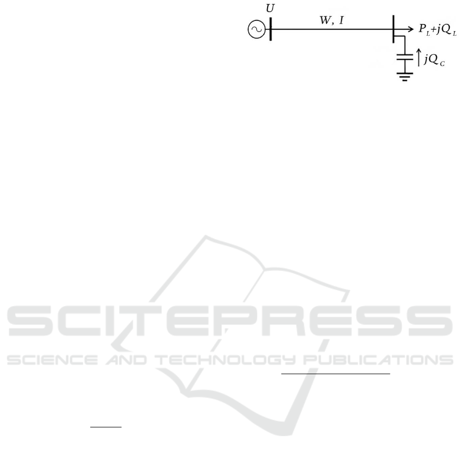
Reactive power Q considering compensation
(Figure 1) is defined with Equation 4:
old c
QQ Q
(4)
where Q
old
is reactive power in the grid before the
compensating device installation, Q
c
is reactive
power compensating device.
As follows from Equations 1-4 power
compensating device depends on the power losses in
the overhead line, and hence on the grid active
resistance.
Figure 1: Single-path distribution network: P
L
, Q
L
are
active and reactive power loads, W is energy transmitted
along the grid.
Dependence of active conductor resistance and
active power losses on the conductor temperature
can be represented by Equations 5, and 6 (IEEE,
2012):
20
(1 ( 20))
tc
RR at
(5)
22
20
20(1 ( ))
c
tt
PIR IR t
(6)
where R
t
and R
20
are active resistances accordingly
when the conductor temperature is t
с
and 20
0
C, α is
temperature coefficient of active conductor
resistance.
The error in determining the resistance and the
active power and energy losses depending on the
conductor temperature relative to the data are
determined with the Equation 7:
20 20
20
(1 ( 20))
100%
( 20)100%
c
c
RR t
R
t
(7)
We represent in Table 1 the uncertainty range of
active power loss determined excluding changes in
conductor temperature.
The accuracy for high-temperature conductors
with transmission capacity can reach 104%.
Significant values of errors are feasibility evidence
of considering the actual conductor temperature to
improve existing methods of electric energy losses
calculation in the overhead power lines.
However, the practical interest is not only to
increase the calculation accuracy but to decrease the
degree of losses due to the appropriate measures
selection.
Optimal Sizing of Capacitor Banks to Reduce Power Losses - With Accounting of Temperature Dependence of Bare Overhead Conductors
175

Table 1: The uncertainty range of active power losses
determined excluding changes in the conductor
temperature.
Type of
conductor
Operating
temperature,
o
С
Uncertainty
range of losses,
%
Bare overhead
conductors
from -50 to +90 56
Overhead
insulation-
covered
conductors
from -50 to +70 48
High-temperature conductors with increased
transmission capacity
TACSR/HACIN
from -50 to
+210
104
TACSR/ACS
from -50 to
+150
80
GTACSR
from -50 to
+150
80
ACCR
from -50 to
+210
104
3 OPTIMAL SIZING OF
REACTIVE POWER
COMPENSATION DEVICES
3.1 Selection of Compensating Devices
by Considering Thermal
Dependencies
The optimization task can be solved on the basis of
the objective function A for reduced costs per annum
(Idelchik, 1989) in accordance with Equation 8
2
2
2
nnr
с
nr spс
etс
e
A Е FM ЕаF С TP P
PQQ
Е
а F С TRpQ
U
(8)
where F is investment for the installation of
capacitor banks, E
n
is capital reduction coefficient,
M is annual operational costs; а
r
is rate of annual
deductions for repairs, maintenance and depreciation
of electrical equipment, С
e
is the electricity cost,
ΔP
c
, ΔP
t
are power loss in capacitor banks and in
overhead line, T is integrating factor transforming
power loss into energy loss and it has the time
dimension, p
sp
is specific losses of active power in
the capacitor banks.
Without considering the temperature dependence
of the resistance the equation for calculating the
capacitor banks optimal power Q
c,opt
is described
with Equation 9
2
c,
2
0
opt
nr e
cc
esp
QQ
AF
Еа СTR
QQU
С Tp
(9)
Resistance considering temperature is variable,
and corresponding derivative is introduced in
Equation 10:
2
2
2
2
2
0
c,opt
nr e
cc
c,opt
eesp
c
QQ
AF
Еа CT R
QQU
PQQ
R
CT CTp
UQ
(10)
Analysis of Equations 9, and 10 shows that the
capacitor banks optimal power determined with
Equation 10 must be greater than the capacitor banks
power defined with Equation 9. This fact is due to
the negative value of the resistance derivative
according to power
/
c
dR dQ
. Indeed, when
increasing Q
c
the grid is discharged; so the
temperature and hence the conductor resistance are
reduced. An exception case is when there is low-
temperature environment and the same time there is
low grid load. But in terms of the losses value, this
case is not worth of detailed consideration.
Temperature calculations are made on the basis
of the heat balance equation for bare conductors
(Goryunov et al., 2016) in accordance with Equation
11
2
44
0
20
(1 ( 20))
()( )
c
c c c amb c amb s s
IR
dtt С TT Aq
t
(11)
where t
amb
is ambient temperature ºC; d
c
is the
conductor diameter; α
c
is coefficient of heat transfer
with convection calculated according to the criteria
of heat transfer processes similarity, ε is conductor
surface emissivity; C
0
is constant of blackbody
radiation; T
c
and T
amb
are the absolute temperatures
of the conductor and the environment (K); A
s
is the
absorption capacity of the conductor surface for
solar radiation; q
s
is solar radiation flux density.
The temperature of bare overhead conductors can
be defined while solving of Equation 11 with an
iterative method in accordance with Equation 12
(Girshin et al., 2016):
SMARTGREENS 2017 - 6th International Conference on Smart Cities and Green ICT Systems
176

1
0.8
'
0
4
4
0
1
1
k
amb
k
c
c
c
c
k
c
ss
amb
tt
p
t
d
CT T Aq
(12)
where k is number of iteration.
3.2 Calculation of the Payback Period
The second stage implementation results to
determine the payback period of the introduced
measures to reduce the energy losses can be
estimated using Equation 13:
,,
pb
in
aft
ein
din daft aft
F
T
MM
F
MM CWW
(13)
where M
in
and M
aft
are annual operating costs,
respectively, in the initial mode and after
introducing measures, M
d,in
is components of the
costs for depreciation, repairs and maintenance of
equipment in the initial mode, M
d,aft
are components
of depreciation, repairs and maintenance costs of the
equipment after introducing measures, ΔW
in
and
ΔW
aft
are energy losses in the initial mode and after
introducing measures.
The analysis of Equation 13 shows:
1. If the calculation errors δ(ΔW
in
) and
δ(ΔW
aft
) are not the same, then the inequality is:
( - ) >>
in aft in
WW W
(14)
( - ) >>
in aft aft
WW W
(15)
2. The error of defining the deadline for
payback period T
pb
for most cases will be larger as
the difference (M
d,in
– M
d,aft
) is usually negative.
3. The first two conditions occur when the
grid element temperature is not considered but it
changes due to measure introduction results.
Reducing the power losses after power factor
correction, with and without considering the heating
is determined with Equations 16, and 17. We note
from Equation 16 that if we consider the temperature
then electric power loss decreases for the following
reasons:
1. By reducing the transmitted reactive power;
2. By reducing the resistance;
3. By reducing transmission losses of active power.
2
2
22
22
2
2
2
in aft
c
sp c
cc
sp c
WW
PQQ
PQ
TR RpQ
UU
QQ Q
TRpQ
U
(16)
2
2
22
22
in aft
c
in aft sp c
WW
PQQ
PQ
TR RpQ
UU
(17)
where R
in
, R
aft
are grid active resistances before and
after the input of capacitor banks which have
different values due to considering the temperature
dependence, besides R
in
> R
aft
.
Equation 16 recorded by assuming the resistance
regardless of the temperature cannot consider these
factors. Despite the positive use of the capacitive
banks in terms of losses reduction, it is necessary to
evaluate the payback period for the capacitor banks
optimal power.
4 NUMERICAL EXPERIMENT
The optimal choice of the compensating devices
parameters and timing payback period are conducted
on the example of a single-path grid shown in Figure
1, with capacitor bank for rated voltages of 10.5 kV.
Research conditions are shown in Table 2.
In the first stage we solve the problem of optimal
choice of capacitor banks at the node 10 kV on the
minimum reduced costs criterion. Selection of only
capacitor banks for medium voltage (10 kV) is due
to simplify the task, since, in the general case the
load is formed with low-voltage (0.4 kV) and
medium voltage (10 kV) components, and therefore,
it is necessary to select a capacitor bank to both
voltage classes. Moreover, we must consider the
presence of the transformer 10/0.4 kV. This
simplified approach is explained with the
independence of the optimal choice of high-voltage
and low-voltage capacitor banks. When there is
optimal choice of capacitor banks (10 kV) then
optimal power of capacitor banks (0.4 kV) is a
function of the transformer parameters 10/0.4 kV, as
well as the corresponding specific costs and own
losses of capacitor banks of both voltage classes.
Optimal Sizing of Capacitor Banks to Reduce Power Losses - With Accounting of Temperature Dependence of Bare Overhead Conductors
177
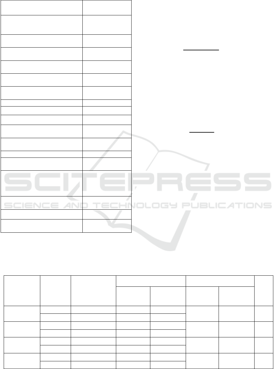
Table 2: Parameter calculation.
Name and designation of
parameters
The numerical
values
Value of the conductor
resistance:
Without heating
Resistance at 20
0
С
Considering heating
Calculated with
equation (5)
Chase resistance of AS-50
conductor at 20 ºC, Ohm/km
0.5951
Radius of AS-50 core conductor,
mm
4.8
Temperature coefficient of
resistance, C
-1
0.00403
Emissivity degree of the
conductor surface
0.6
Air temperature, ºC
1.7
Atmospheric pressure, Pa 100000
Wind speed, m/s 1
Solar radiation flux density,
W/m
2
230
Integrating factor, transforming
power loss into energy loss,h
5000
Cost of electricity, rubles/(kW∙h) 2.098
Coefficient of bringing
investment, 1/year
0.14
Rate of annual deductions for
repairs, maintenance and
depreciation of electrical
equipment
0.059
Specific active power losses in
capacitor banks, kW/kVAR
0.002
Voltage in the load node Does not change
Conductor temperature without
capacitor banks
Close to the
maximum
The results of studies on the optimal choice of
capacitor banks for AS-50 bare conductor with and
without considering the conductor heating are shown
in Table 3. The calculation without accounting of
conductor temperature is classical approach for
sizing of capacitor banks (Kalambe and Agnihotri,
2014). Determination of the optimal power increase
capacitor banks considering heating Q
c,opt,t
relative
the optimal power without considering heating Q
c,opt
was carried out according to Equation 18:
, , ,opt
1
,
100%
c opt t c
c opt
QQ
Q
(18)
We presented in Table 4 the results of payback
periods calculation for optimal power of capacitor
banks corresponding to Table 3. The calculation of
the payback period was performed on Equation 13.
The relative differences of defining the payback
period due to the neglect of bare overhead
conductors heating is calculated according to
Equation 19: T
2
100%
pb pbt
pb
ТТ
Т
(19)
The analysis of results given in Tables 3 and 4
allows making the following conclusions:
1. The optimal heating power considering the
optimal power is either equal to optimal power
without heating or exceeds it by one or two nominal
values. The mean excess value ε
1
,
calculated
according to Equation 18 and based on Table 3 data
is 25%.
2. Presented in Table 4 calculation results
according to Equation 19 show that the payback
period of compensating devices considering heating
may be reduced to 20-65%. These indicators of
economic efficiency prove the need to consider
heating factor when choosing compensating devices,
in particular, when installing capacitor banks.
Table 3: Optimal power of capacitor banks for AS-50 conductors at power load P
L
=3300 kW, Q
L
=2500 kVAR.
The grid
length,
m
Q
c
, kVAR
Capacitor banks
cost,
thousand rubles
A, thousand rubles
Q
c,opt
, kVAR
ε
1
, %
Without
considering
t
c
Considering
t
c
Without
considering
t
c
Considering
t
c
200
900 169.4 220.5 241.8
900 1350 50
1350 215.2 223.6 240.2
300
1350 215.2 299.9 324.7
1350 1350 0
1500 258.9 305.7 328.7
380
1350 215.2 360.9 392.4
1350 1800 33
1800 270.9 361.6 387.8
650
1800 270.9 553.4 598.2
1800 2250 25
2250 329.6 557.2 597.3
SMARTGREENS 2017 - 6th International Conference on Smart Cities and Green ICT Systems
178

Table 4: Payback period of capacitor banks installation for AS-50 conductors with load capacities P
L
=3300 kW, Q
L
=2500
kVAR.
The grid length,
m
Calculation without
considering t
c
Calculation considering t
c
ε
2
, %
Q
c,opt
, kVAR T
pb
, years Q
c,opt,t
, kVAR T
pbt
, years
200 900 9.8 1350 5.0 48.9
300 1350 4.2 1350 2.6 38.1
380 1350 2.8 1800 2.1 25.0
650 1800 1.5 2250 1.2 20.0
5 CONCLUSIONS
The paper discussed the problem of optimal choice
of compensating devices in distribution network.
The main originality of suggested approach is
considering the bare overhead conductors heating.
Numerical results prove the high economic efficient
of accounting real conductor temperature while
sizing of capacitor banks. In general, the economic
effect from the considered measure introduction can
be much more by analyzing the grid and improving
the thermal mode of the grid due to the load
reduction.
Obtained results give capabilities for future
researches in the field of reactive power
compensation including smart grids and distributed
generation systems. One of smart grid features is
temperature control of the network elements.
Developed algorithm consider the temperature in
optimization processes and can be used in smart
grids.
REFERENCES
Cigre Working Group 22.12, 2002. Thermal behaviour of
overhead conductors. Cigr´e Brochure 207.
Das, B., Varma, P.K., 2001. Artificial neural network
based optimal capacitor switching in a distribution
system, Electric Power Systems Research, vol.60,
pages 55-62. Elsevier.
Das, D., 2008. Optimal placement of capacitors in radial
distribution system using a Fuzzy-GA method,
Electrical Power & Energy Systems, vol. 30, pages
361-367. Elsevier.
Da Silva, E. L., Gil, H. A., and Areiza, J. M., 2000.
Transmission network expansion planning under an
improved genetic algorithm. IEEE Transactions on
Power Systems, vol.15, np. 3, pages 1168-1174. IEEE.
Girshin, S., Goryunov, V., Kuznetsov, E., Petrova, E.,
Bubenchikov, A., and Batulko, D., 2016. Thermal
Rating of Overhead Insulation-Covered Conductors in
the Steady-State Regime. In MATEC Web of
Conferences,
vol. 70, page 10006. EDP Sciences.
Goryunov, V. N., Girshin, S. S., Kuznetsov, E. A.,
Petrova, E. V., and Bigun, A. Y., 2016. A
mathematical model of steady-state thermal regime of
insulated overhead line conductors.
In 2016 IEEE 16th
International Conference on Environment and
Electrical Engineering
, pages 1-5. IEEE.
Haghifam, M. R., & Malik, O. P., 2007. Genetic
algorithm-based approach for fixed and switchable
capacitors placement in distribution systems with
uncertainty and time varying loads. IET generation,
transmission & distribution, vol. 1, no. 2, pages 244-
252.
Idelchik, V.I., 1989
Electrical systems and grids, М. :
Energoatomizdat.
IEEE Std. 738, 2012. Standard for Calculating the
Current-Temperature Relationship of Bare Overhead
Conductors. IEEE.
Isac, S. J., Kumar, K. S., & Kumar, P. V., 2013. Optimal
capacitor placement in radial distribution system to
minimize the loss using fuzzy logic control. In Smart
Structures and Systems, IEEE International
Conference on, pages 33-40. IEEE.
Kalambe, S., and Agnihotri, G.,2014. Loss minimization
techniques used in distribution network:
bibliographical survey. Renewable and sustainable
energy reviews, vol. 29, pages 184-200. Elsevier.
Mohsin, Q. K., Lin, X., Flaih, F. F., Dawoud, S. M., and
Kdair, M., 2016. Optimal placement and capacity of
capacitor bank in radial distribution system. In Energy
Efficient Technologies for Sustainability, 2016
International Conference on, pages 416-423. IEEE.
Morgan, V. T., 1982. The thermal rating of overhead-line
conductors Part I. The steady-state thermal model.
Electric power systems research, vol. 5, no. 2, pages
119-139. Elsevier.
Rao, R. S., Ravindra, K., Satish, K., and Narasimham, S.
V. L., 2013. Power loss minimization in distribution
system using network reconfiguration in the presence
of distributed generation.
IEEE Transactions on
Power Systems
, vol. 28, no. 1, 317-325, IEEE.
Reddy, K. S. K., and Reddy, M. D., 2015. Optimal
placement of capacitor in distribution networks using
fuzzy and SFLA. In International Conference
on Electrical, Electronics, Signals, Communication
and Optimization, pages 1-5. IEEE.
Optimal Sizing of Capacitor Banks to Reduce Power Losses - With Accounting of Temperature Dependence of Bare Overhead Conductors
179
