
Cooperative Communication Network for Adaptive Truck Platooning
Razvan Andrei Gheorghiu, Valentin Iordache and Angel Ciprian Cormos
Transport Faculty, Electronics Dept., “Politehnica” University of Bucharest, Splaiul Independentei, Bucharest, Romania
Keywords: Truck Platooning, Road-train, Vehicle-to-Vehicle Communications, ZigBee.
Abstract: Truck platooning represents a solution to increase energy efficiency of the freight road transport. This method
assumes very little distance between trucks so that overall aerodynamic quotient is improved. However, this
requires a specific and dedicated infrastructure, due to the fact that the total length of the convoy may be
considerable, which has a negative impact on the general traffic: other vehicles need a lot of space (and time)
to overtake the platoon and this can only be done on highways with more than two lanes / direction. This
means that in most cases (national roads and less wide highways) platoons cannot be formed and this method
cannot be implemented. To resolve this situation, in this article we have proposed a solution for dynamic
platoon formation, based on vehicle-to-vehicle communications, that will allow other vehicles to gradually
overtake the vehicles forming the platoon. For this, a communication technology proposal has been made to
ensure the identification of vehicles that are obstructed by the platoon. We have also made a series of
laboratory measurements to test the validity of the proposed solution and, in the end, presented our
conclusions.
1 INTRODUCTION
Vehicle platooning is a relatively new concept that
can provide many benefits, such as improved vehicle
safety, improved fuel consumption due to less
aerodynamic drag (and, hence, reduced
environmental pollution) (Kavathekar, 2012).
For the realization of the platoon, the vehicles
composing it must have fully automated longitudinal
and lateral control to be able to maintain the same
spacing between all platoon members at all speeds, as
they travel through the road network. This kind of
automation increases safety for all involved vehicles.
With very small headway spacing, as little as a few
meters, the vehicles follow each other. The key
element is a very reliable communication system: the
lead vehicle (LV) of the platoon continuously
broadcasts to the following vehicles (FV),
information on the maneuvers that the platoon is
going to execute.
This approach is highly studied and there are
many details provided on what systems need to be put
in place to create a platoon and how the
communications between vehicles should be
implemented to ensure the minimum distance
between vehicles (European Commission, 2014;
Bergenheim et al, 2012a; Bergenheim et al, 2012b;
Janssen et al, 2015). Platooning concept has been
tested in real life conditions in several projects, such
as SARTRE (SARTRE-Consortium, 2012), PATH
(Lu and Shladover, 2011; Nowakowski et al, 2015) or
KONVOI (Institute for Automotive Engineering,
2009).
But all approaches, as far as our knowledge, refer
to the creation of a platoon with fixed distance
between vehicles. Studies have shown even the
necessity to implement a dedicated infrastructure for
this type of road train. This is a proper approach when
we consider only the fuel economy and the other
benefits of platooning without caring for price. This
solution is very expensive to implement and it can’t
be used for most of the existing roads due to the fact
that for longer platoons it is very difficult for other
vehicles to overtake the vehicles in the platoon.
The concept of vehicle platooning may be applied
to all the vehicles but, as energy efficiency is the
primary goal of this concept, we shall analyze only
the truck platooning concept in the rest of the article,
considering that for the other types of vehicles this
desiderate is not the primary goal. Also, in order to
simplify the first concept of the system, we shall
consider only the highway scenario, as platoon
formation on national roads imply even more
challenges and issues that have to be further analyzed.
228
Gheorghiu, R., Iordache, V. and Cormos, A.
Cooperative Communication Network for Adaptive Truck Platooning.
DOI: 10.5220/0006302402280235
In Proceedings of the 3rd International Conference on Vehicle Technology and Intelligent Transport Systems (VEHITS 2017), pages 228-235
ISBN: 978-989-758-242-4
Copyright © 2017 by SCITEPRESS – Science and Technology Publications, Lda. All rights reserved

This desiderate can only be achieved when there is a
certainty that all the vehicles travelling that road have
autonomic capabilities, which, for sure, will not
happen in the near future.
2 DYNAMIC PLATOONING
CONCEPT
2.1 System’s Concept
Dynamic platooning is a method of platoon formation
for which the distance between vehicles is not fixed.
The distance tends to be minimum when other
vehicles are not around, but gaps may be formed in
the platoon to let outside vehicles (OV) travel without
obstruction from the platoon.
We shall consider two scenarios: one in which an
OV intends to overtake the platoon. Such a system
implies the last of the platoon’s FVs to detect the OV.
This may be achieved by vehicle-to-vehicle (V2V)
communications, if OV is capable of it and has
implemented the proper equipment compatible with
the ones installed on the platoon’s vehicles. However,
if the OV does not have V2V capabilities, there is the
need to also implement a vehicle detection system
with the purpose of identifying the OVs that intend to
overtake the platoon, and an information method for
other traffic participants to let them know in what way
the platoon may be overtaken.
The other scenario is the one in which an OV
intends to exit the highway and the platoon is
positioned in its path to the exit lane. Such a system
implies V2V communication system implemented on
all the vehicles because the OV trying to exit must
inform the platoon about its intentions. But to
implement such a system is mandatory to have
knowledge about the exact position of the OV, in
order to determine the position in the platoon where
the gap should be formed. Location is usually found
via global positioning systems, such as GPS or
GLONASS. All these systems, however, involve a
location precision error, that may be up to several
meters. Modern GPS receivers can now deliver high
accuracies (centimeter level) with the help of real
time kinematic navigation or differential GPS, both
depending on the existence of ground-based reference
stations. In cities, additional information may be
added to the positioning system from the GSM
network, via A-GPS (assisted GPS). This increases
location precision and reduces error to several
centimeters. But outside the cities, where there are
only few GSM antennas and GPS ground stations are
not always available, precision cannot be as good.
This may lead to malfunction of the whole dynamic
platoon concept, as there is not a certainty that the gap
produced to allow the vehicle to go through the
platoon to exit the highway is properly placed.
Therefore, in order to achieve a good functionality
of the whole system, it is necessary to implement
some additional fixed detection points located certain
distance ahead of the exit points that will locate with
great precision both the exiting vehicle and all the
trucks in the platoon. Then, by sending the
information to the platoon, the trucks may decide with
proper knowledge what the gap position should be.
In both scenarios, when the gap between vehicles
is formed, the platoon is split in two. Considering the
platoon concept, there is a safety concern if the
platoon would be considered intact when an outside
vehicle is integrated in it. This happens because the
FV’s assume that, in case of an emergency, they
would receive the necessary information (like
braking) in due time from the LV. If the distance
between platoon vehicles became too big (in case of
a gap formation) the information may arrive late at
the vehicles behind the gap. Also, the uncertainty
induced by the behavior of the external vehicle is a
safety risk.
There is also the case that must be foreseen in
which an additional external vehicle fills in the gap
formed, hence having two vehicles intruding in the
platoon, instead of only one. It is important in this
case for the vehicles in the gap area to figure out when
the external vehicles have left the platoon in order to
get close together again. If all the vehicles are still
considered as a single platoon it is very difficult to
detect when the intruders have left, especially
considering that OVs may not have V2V capabilities.
Also, if OVs reduce their speed, there may be a
communication problem for the maintenance of the
platoon, due to a possible distance between platoon
vehicles bigger than the maximum reliable V2V
communication distance.
Based on all the above considerations, we have
concluded that the proper solution is to temporary
form two separated platoons, meaning that the FV
behind the gap become the LV of the new second
platoon. When the OV leaves the gap the two
platoons may reunite as one.
In Figure 1 the stages of overtaking the platoon
are shown:
OV intends to overtake the platoon and is
detected.
OV overtakes the last two vehicles, splitting the
platoon in two.
Cooperative Communication Network for Adaptive Truck Platooning
229
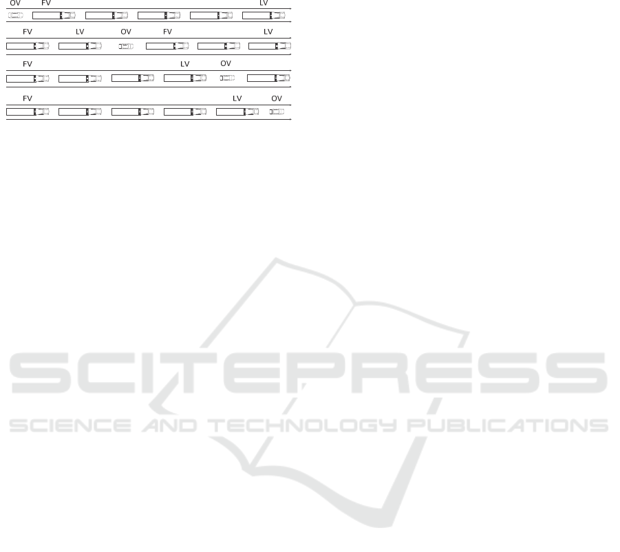
OV overtakes the next two vehicles; the initial
LV is no longer part of the platoon.
The initial platoon is reformed.
Figure 1: OV overtaking a platoon.
It is obvious that, in this case, it’s not possible to
have a LV with human driver and for all the other
ones the autonomous system to have full control. As
any FV may become a LV (at least temporary), it is
important to implement a driver alert system, that will
inform a FV’s driver about the transformation to LV.
2.2 System Requirements
Considering the above system description, the
following elements must be included in order to
obtain the desired functionality (Kavathekar, 2012;
SARTRE-Consortium, 2012):
For longitudinal control, when the vehicle in
front is part of the platoon, V2V
communication will be used to exchange
performance parameters (speed, braking,
acceleration, detected obstacles, steering, etc.)
between LV and FV’s. To maintain a certain
distance between platoon members on board
systems like Adaptive Cruise Control (ACC),
that automatically adjusts the vehicle speed to
maintain a specified distance from the vehicle
in front, or Collision Avoidance Systems
(CAS) will be used.
For longitudinal control, when the vehicle in
front is not part of the platoon (for example an
OV that enters in the middle of the platoon), the
FV decelerates to increase the gap to the OV in
order to provide a larger safety margin, by
using on board systems like ACC or CAS.
Lateral control can be achieved by using on
board systems. Lane departure keeping systems
are used to ensure that the vehicle remains in its
lane. Magnetic markers or reflective guardrails
can be installed in the road infrastructure also
to be detected by on board systems.
Identification of vehicles requiring a gap may
be done using V2V communications, if OV
have such a system implemented, or it will be
done using video cameras to detect an
overtaking vehicle that requires a gap.
Information system is necessary to inform
other vehicles that do not have V2V
implemented about their permissions related to
the platoon’s movement. Each truck forming
the platoon should have a VMS (variable
message sign) or LCD on their back to display
information such as: “Overtaking not allowed”,
“Overtake one truck”, “Overtake two trucks” or
other information messages.
Communication systems – detailed in the next
chapter.
3 DYNAMIC PLATOONING
CONCEPT
3.1 Communication Network
Architecture
The communications that must be considered are
(Vlastaras et al, 2014; Amoozadeh et al, 2015):
For communication between vehicles in the
platoon, with the purpose to maintain the
platoon, dedicated short range communication
technologies will be necessary, that must be
very robust, with very short delay and with
safety and security mechanisms implemented.
Depending on the length of the platoon and the
used technology one can choose a centralized
or decentralized approach.
The main consideration should be the message
propagation time, to assure that an emergency
command will be received in due time by all the
vehicles in the platoon. This gives the main
restriction to the platoon length.
In addition, it is more reliable to have a single
message sent from LV to all FVs than to have
the message rebroadcast by every FV: any error
in a FV will break or, worse, distort the
message that will be sent to the rest of the
platoon’s vehicles.
For communication between vehicles in the
platoon, with the purpose to create/recreate the
platoon, the same dedicated short range
communication technologies will be necessary
and also a Human-Machine Interface (HMI) for
the driver to interact with the system.
Identification of vehicles requiring a gap, if
they have V2V communications implemented,
VEHITS 2017 - 3rd International Conference on Vehicle Technology and Intelligent Transport Systems
230

will be done through wireless exchange of data
between LV and OV, establishing a protocol
for asking and receiving a gap in the platoon,
based on OV’s location.
Infrastructure to vehicle (I2V) communications
will be necessary for the second scenario, to
accurately locate the OV that intends to exit the
highway with the help of roadside beacons
placed before the exits. The same dedicated
short range communication technologies will
be used.
Global Navigation Positioning System that will
provide vehicle location.
All these are presented in Figure 2.
Figure 2: Example of communications for the platoon.
3.2 Platoon Formation Concepts
Platoons must have a unique ID that will allow the
vehicles to identify at which platoon they adhere. This
must be negotiated at the beginning of the platoon
formation, when the first FV ask permission to join
the LV. The ID should include the following
elements:
GPS coordinates of the place the first
negotiation of the platoon took place.
Direction of travel, considering geographical
positions: N, NE, E, SE, S, SW, W, NW.
Type of FV.
A random number.
From all the above it results that the platoons will
have different IDs so they will be easily identified.
When an OV breaks the platoon in two, the second
platoon will have a new ID, given by the above
considerations. When a platoon arrives in the
proximity of another platoon going the same direction
(also the case when an OV broke the platoon and then
left), the second LV must communicate with the first
LV to negotiate a formation of a bigger platoon
including all the vehicles.
4 CONSIDERATIONS
REGARGING MINIMUM
DISTANCE FOR
ESTABLISHING
COMMUNICATION
For the scenario in which an OV intends to exit the
highway and the platoon is placed between it and the
exit lane, the OV must inform the platoon and ask for
a gap in it, using V2V communications. In this case,
it is very important to see if there is enough distance
available for the vehicle to follow all necessary steps
and safely exit the highway.
The minimum distance (D) for establishing a
communication with the platoon must be bigger than
the minimum calculated distance (d) to the highway
exit.
(1)
Minimum calculated distance is a sum of
distances travelled by the vehicle and the length of the
highway exit lane:
∙
∙
(2)
where: l
el
is the length of the highway exit lane (if one
exists).
v
pt
is the platoon’s speed.
t
rt
is the necessary time for the platoon to
create the gap.
t
in
is the necessary time for the vehicle to
occupy the gap.
d
syn
is the necessary distance for speed
synchronization between the OV and the
platoon.
v
ov
is the OV’s speed.
t
COM
is the necessary time for exchanging
messages.
The time needed for the vehicle to occupy the gap
(t
in
) include necessary time for signaling a lane
change (t
sig
) and the necessary time for performing the
maneuver (t
man
) without making sudden movements.
(3)
where: w
l
is the lane width.
v
lat
is the lateral speed.
In order to provide enough space for the OV, the
platoon must be split in two. The time required to
separate the platoon (t
bp
) depends on the length of the
OV (l
ov
), a safe distance (d
s
) to leave between it and
the trucks (both in front and behind the car) and the
trucks braking acceleration (a
brt
).
Cooperative Communication Network for Adaptive Truck Platooning
231

2
2
(4)
The OV that is overtaking the platoon is supposed
to have the right to travel at a superior speed, so, in
order to execute the maneuver for splitting the
platoon and exiting the highway, the OV must slow
down and synchronize its speed with the platoon. The
distance travelled by the OV from platoon split
confirmation until it reaches the same speed is
calculated as follows:
∙
(5)
where: a
brv
is the vehicle braking acceleration
In conclusion, the total necessary distance is:
∙
∙
∙
2
2
(6)
As can be seen from (6), minimizing the distance
and creating an efficient system will depend heavily
on the necessary time for exchanging messages
between the OV and the platoon, therefore choosing
the right communication technology will be a very
important step.
5 PROPOSED
COMMUNICATION
TECHNOLOGY
As the authors concluded in (Gheorghiu and
Iordache, 2016) ZigBee protocol represents an
alternative to Bluetooth and Wi-Fi communications
for vehicular environments, being developed to
ensure better energy consumption, even with the
downside of lower data rates. Its main advantages are
fast handshake connection (30 milliseconds), less
interference from other 2.4GHz technologies (two of
the ZigBee channels, 24 and 25, have less to no
conflict with Wi-Fi and Bluetooth channels) and high
equipment availability with accessible prices. DSRC
technology, although developed especially for V2V
communications, was not included in the comparison
because of expensive equipment and low availability.
The ZigBee standard is built on IEEE 802.15.4 for
packet-based wireless communication and enhances
its functionality by providing flexible, extendable
network topologies with integrated set-up and routing
intelligence to facilitate easy installation and high
resilience to failure. Usually it operates in the 2.4GHz
band worldwide and uses offset quadrature phase-
shift keying (OQPSK), that transmits two bits per
symbol. The data rate varies widely, depending on the
implementation, from 20 kbit/s to 250 kbit/s (ZigBee
Alliance, 2016).
Related to road traffic communications, ZigBee
has the advantage of being very flexible and allowing
networks to be easily adjusted to changes by adding,
removing or moving network nodes. The protocol is
designed such that nodes can appear in and disappear
from the network, making it very adaptable and
proper for V2I communication. Another big
advantage of a ZigBee network is that it can easily be
installed and configured. The devices are also cheap,
facilitating a large-scale implementation.
There are three methods to create a ZigBee
network: pre-configured (all parameters are
configured by the manufacturer), self-configuring
(the network is set up by "discovery" messages sent
between devices) and custom (adapted for specific
applications/locations) (NXP Laboratories, 2014).
As ZigBee nodes are usually in sleep mode to
achieve low power consumption, they need some
time to wake up and respond, typically 15
milliseconds for a sleeping node to wake up, and
another 15 milliseconds to access the channel.
Compared to other wireless communications for short
distances, such as Bluetooth or Wi-Fi, this latency
time can be considered to be low.
The ZigBee protocol has many advantages from
the connection time point of view, but the data rate
available may not be enough for some applications.
However, considering the details that will be
formulated below, we shall be able to conclude that
this technology presents enough advantages to be
considered as a possible solution to the application
that is presented in this paper.
ZigBee networks may co-exist with Bluetooth and
Wi-Fi, as they incorporate listen-before-talk protocol
and rigorous security measures. As presented in
(Gheorghiu and Iordache, 2016) Wi-Fi interferences
over ZigBee communications are the most important
and most likely to occur in a road environment. As
can be seen in Figure 3 and as was shown in the same
paper, channel 26 is the most resilient to interferences
caused by Wi-Fi communications, when it comes to
handshake connection times, so the following tests
will be based on these conclusions.
VEHITS 2017 - 3rd International Conference on Vehicle Technology and Intelligent Transport Systems
232
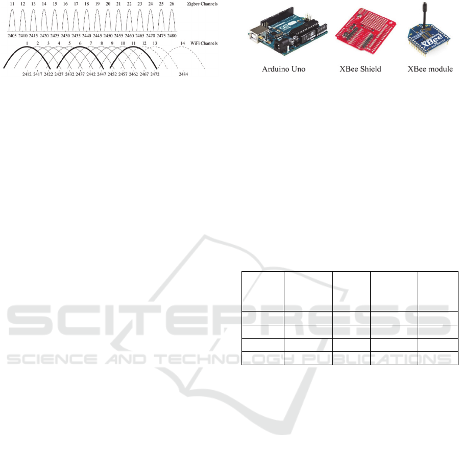
Figure 3: ZigBee and Wi-Fi Channels (Liang et al., 2010).
6 MESSAGE EXCHANGE TIME
MEASUREMENTS
In order to measure the necessary time for exchanging
messages a typical message set structure has to be
defined, based on the information needed by the
system. Two messages are defined, one for the
request sent from the OV to the platoon, and one for
the response sent from the platoon to the OV.
Proposed request message contains 152 bits and,
based on our calculations from chapter IV, includes
the following information:
Vehicle ID (random): 64 bits.
Type of request: 8 bits.
GPS position of the OV: 32 bits.
Speed of the OV: 8 bits.
Length of the OV: 8 bits.
GPS position of the highway exit (if this is the
case): 32 bits.
Proposed response message contains 32 bits and
include the following information:
Acceptance or rejection of the request: 16 bits.
Number of the truck in front of which a gap will
be created: 8 bits.
Recommended speed for the OV: 8 bits.
Based on the OV’s request, the last FV of the
platoon will determine if the distance between the
platoon and the highway exit is sufficient for a
successful platoon separation, integration and exit of
the OV. If there is not enough space, the request will
be rejected and the vehicle will be informed to wait
for the highway exit behind the platoon.
In the following, is presented an analysis of the
time needed for transmitting successful messages
between OV and LV/FV, performed in the laboratory,
using the following hardware: one router and four
XBee S2 modules, each connected to an Arduino Uno
board with an XBee Shield (Figure 4).
Figure 4: Hardware components.
The authors chose to use these ZigBee
implementation modules because of their reasonable
price and high availability in many countries.
An XBee 2mW Wire Antenna - Series 2 was used
for these tests, having the following main technical
characteristics: 3.3V @ 40mA needed power supply,
250kbps Max data rate, 2mW output (+3dBm), 120m
range. Two pairs of transceivers were created, each of
them with one of the XBee modules set as
Coordinator – XB
C
and the other as End Device –
XB
ED
. Every pair was configured using the
parameters presented in Table 1.
Table 1: XBee Coordinator and End Device configuration.
Modified
parameters
Coordinator
settings
(pair 1)
End
device
settings
(pair 1)
Coordinator
settings
(pair 2)
End
device
settings
(pair 2)
PAN ID 11 11 10 10
DH 13A200 13A200 13A200 13A200
DL 40E778BF 40E7795C 40E922BF 40E922BD
BD 57600 57600 57600 57600
PAN ID (Personal Area Network ID) identifies
the network that the device will join. This parameter
was set differently for every pair of transceivers, to
avoid unwanted connections between the four
modules and joining other possible existing networks.
DH represents the upper 32 bits and DL is the
lower 32 bits of the 64-bit destination extended
address. Each device in one pair was configured with
DH and DL of the other device, so they will
communicate with each other.
BD represents the Baud Rate, and it was chosen a
value sufficient for transmitting necessary data.
The tests focused on measuring the time needed
for a complete exchange of messages (one request
and one response) between two XBee modules, one
that should be on board of the OV, and the other on
board of the LV/FV. Messages have been formed as
described earlier in this paper.
Three scenarios were considered:
Message exchange with random Wi-Fi
interference (considering that it is not possible
to know very precise what communications
Cooperative Communication Network for Adaptive Truck Platooning
233
will occur during the exchange of messages in
the ZigBee network).
Message exchange with a wireless router set on
the Wi-Fi channel closest to the tested ZigBee
channel, and a large file transfer in progress
during this phase of the tests.
Message exchange with another pair of XBee
modules set on the same communication
channel as the ones used for measurements, and
transmitting data with a high rate.
As stated in previous chapter, the authors chose to
measure and compare message exchange times for 2
of the 16 ZigBee channels, channel 12 that is clearly
overlapping with Wi-Fi channel 1, and it will
certainly be affected by a heavily data transfer, and
ZigBee channel 26, whose frequency band is less
likely to be occupied by a data transfer on Wi-Fi
channel 13.
Five tests were performed:
Message exchange on ZigBee channel 12
(0x0C), with random Wi-Fi communications.
Message exchange on ZigBee channel 12
(0x0C), with Wi-Fi communications set on
channel 1.
Message exchange on ZigBee channel 26
(0x1A), with random Wi-Fi communications.
Message exchange on ZigBee channel 26
(0x1A), with Wi-Fi communications set on
channel 13.
Message exchange on ZigBee channel 26
(0x1A), with another ZigBee communication
active on the same channel.
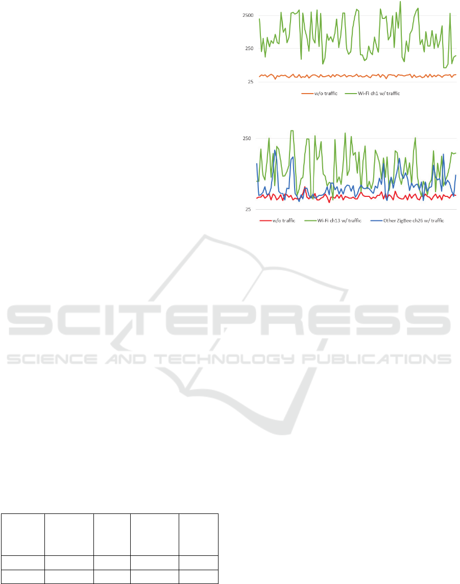
A number of 100 measurements were performed
for each test. Median values for the message
exchange time can be seen in Table 2 and all values
can be seen by comparison in Figure 5 and Figure 6,
based on used ZigBee channel.
Table 2: Median values obtained in tests (milliseconds).
ZigBee
channel
Normal
Conditions
Wi-Fi
channel 1
active
Wi-Fi
channel 13
active
Another
ZigBee
channel
26 active
12
38 499 - -
26
37 - 78 50
Figure 5: Message exchange time (ms), ZigBee channel 12.
Figure 6: Message exchange time (ms), ZigBee channel 26.
The charts presented above leads us to the
following conclusions:
For ZigBee channel 12, that overlaps Wi-Fi
channel 1, it results a distinguishable difference
between the case with no traffic and the scenario with
Wi-Fi traffic on channel 1. Considering a speed
difference between OV and the last FV of the platoon
of 8.5m/s (about 30.6 km/h – with a platoon traveling
at 100 km/h and the OV’s speed of 130 km/h), and a
communication distance of 50m (25m before OV
reaches FV and 25m after it overtakes FV – a
moderate value, considering that, in theory, ZigBee
communications reach 70m in open field => 140m
total distance) results a total communication time of
50/8.5 = 5.88 seconds. Therefore, a total transfer time
of 4.098 seconds (maximum obtained in tests) may
still be proper for the requirement/acknowledge
communication.
For ZigBee channel 26, the situation is even
better, as in our tests the maximum
requirement/acknowledge communication time was
365 milliseconds and, consequently, this represents a
proper OV-FV communication solution.
7 CONCLUSIONS
As the result of the tests performed, we may conclude
that ZigBee seems to be a proper solution for V2V
communications between OV and FV, providing
enough time for data exchange (considering that the
VEHITS 2017 - 3rd International Conference on Vehicle Technology and Intelligent Transport Systems
234

message’s length is reduced), as the speed difference
between OV and the platoon is not very high.
The tests have been made in all the possible
scenarios: lowest, random and highest Wi-Fi
interference, and the values obtained proved to be
enough to ensure the proper OV-FV communication.
The next steps will refer to modelling in detail the
communication network that will reliably deliver
messages needed to guide the platoon and to support
the right assistance in interaction with the other
vehicles. Laboratory measurements with more
aggressive electromagnetic noise are foreseen. Also
measurements in a real vehicular environment will be
performed to validate the laboratory tests.
ACKNOWLEDGEMENTS
This work has been funded by University Politehnica
of Bucharest, through the “Excellence Research
Grants” Program, UPB – GEX. Identifier: UPB–
EXCELENȚĂ–2016 Research project title
“VEHINET – Rețea cu conținut informațional
adaptiv la condițiile mediului destinată deplasării
inteligente a vehiculelor”, Contract number
45/26.09.2016 (acronym: VEHINET).
REFERENCES
Alexander, L., Phanomchoeng, G., Rajamani, R., 2013.
Instrumentation of Navistar Truck for Data Collection.
Published by: Minnesota Department of Transportation
Research Services
Amoozadeh, M., Deng, Hui, Chuah, C.N., Zhang, M.,
Ghosal, D., 2015. Platoon Management with
Cooperative Adaptive Cruise Control Enabled by
VANET. Vehicular Communications Journal, Volume
2, Issue 2, April 2015, Pages 110–123
Bergenhem, C., Pettersson, H., Coelingh, E., Englund, C.,
Shladover, S., Tsugawa, S., 2012. Overview of
platooning systems. 19th ITS World Congress, October
22-26, Vienna, Austria
Bergenheim, C., Shladover, S., Coelingh, E., 2012.
Overview of platooning systems. Proceedings of the
19th ITS World Congress, October 22-26, Vienna,
Austria
European Commission, 2014. Strategy for reducing Heavy-
Duty Vehicles' fuel consumption and CO2 emissions.
Communication from the Commission to the Council
and the European Parliament, Brussels
Gheorghiu, R.A., Iordache, V., 2016. Analysis of vehicle to
infrastructure (V2I) communication efficiency using the
ZigBee protocol. Proceedings of the third International
Conference on Traffic and Transport Engineering,
November 24-25, Belgrade, Croatia
Institute for Automotive Engineering, 2009. KONVOI
Project. Available at: https://www.ika.rwth-
aachen.de/en/research/projects/driver-assistance-
vehicle-guidance/1636-konvoi.html (Accessed: 14
November 2016)
Janssen, R., Zwijnenberg, H., Blankers, I., de Kruijff, J.,
2015. Truck platooning. Driving the future of
transportation. Report number: TNO 2014 R11893
Kavathekar, P., 2012. Cognitive vehicle platooning in the
era of automated electric transportation. Master of
Science Thesis, Utah State University, Logan, Utah,
USA
Liang, C.J.M., Priyantha, N.B., Liu, J., Terzis, A., 2010.
Surviving wi-fi interference in low power ZigBee
networks. In Proceedings of the 8th ACM Conference
on Embedded Networked Sensor Systems (SenSys).
ACM.
Lu, X.Y., Shladover, S., 2011. Automated Truck Platoon
Control. PATH Project
Minea, M., 2015. Cooperative V2V Clustering Algorithm
for Improving Road Traffic Safety Information. IEEE
12th International Conference on Advanced
Technologies, Systems and Services in
Telecommunications – TELSIKS 2015, October 14-17,
Nis, Serbia
Minea, M., Badescu, I., Dumitrescu, S., 2011. Efficiency of
Multimodal Real-Time Travel and Traffic Information
Services Employing Mobile Communications. 10th
International Conference on Telecommunications in
Modern Satellite, Cable and Broadcasting Services
IEEE Proceedings Volume 1, pp. 765-769, October 5 –
8, TELSIKS 2011, Nis, Serbia
Nowakowski, C., Shladover, S., Lu, X.Y., Thompson, D.,
Kailas, A., 2015.
Cooperative Adaptive Cruise Control
(CACC) for Truck Platooning: Operational Concept
Alternatives. PATH Project
NXP Laboratories, 2014. ZigBee PRO Stack. User Guide.
JN-UG-3048, Revision 2.5
SARTRE-Consortium, 2012. SARTRE Project. Available
at: www.sartre-project.eu (Accessed: 14 November
2016)
Surugiu, M.C., Stancel, I.N., 2015. Fleet Management
Cooperative Systems for Commercial Vehicles. 9th
International Conference Interdisciplinarity in
Engineering, INTER-ENG 2015, 8-9 October 2015,
Tirgu Mures, Romania
Vlastaras, D., Abbas, T., Nilsson, M., Whiton, R., Olbäck,
M., Tufvesson, F., 2014. Impact of a Truck as an
Obstacle on Vehicle-to-Vehicle Communications in
Rural and Highway Scenarios. 6th International
Symposium on Wireless Vehicular Communications,
DOI: 10.1109/WIVEC.2014.6953226
ZigBee Alliance, 2016. ZigBee Specifications. Available at:
www.zigbee.org (Accessed: 22 November 2016)
Cooperative Communication Network for Adaptive Truck Platooning
235
