
A Causal Semantics for UML2.0 Sequence Diagrams with Nested
Combined Fragments
Fatma Dhaou
1
, Ines Mouakher
1
, J. Christian Attiogb
´
e
2
and Khaled Bsaies
1
1
Lipah, Faculty of Sciences, University Tunis El Manar, Tunis, Tunisia
2
Lina, University of Nantes, France
Keywords:
UML2.0 Sequence Diagrams, Semantics, Nested Combined Fragments.
Abstract:
Combined Fragments (CF) are the new features added to UML2.0 sequence diagrams (SD). They have widely
increased its expressiveness power, permitting to model complex behaviours, they can be nested to allow more
sophisticated behaviours. We focus on the most popular CF of control-flow ALT, OPT, LOOP, SEQ allowing
to model respectively alternative, optional, iterative and sequential behaviours. They require a meticulous
processing for the generation of partial order between their events. We proposed in a previous work, a causal
semantics based on partial order theory, which is suitable for deriving of all possible valid traces for sequence
diagrams with CF modelling behaviours of distributed systems. In this work, to deal with nested CF, we first
update the formalization of sequence diagram, then we extend this semantics.
1 INTRODUCTION
Context. The speed of design, the intuition and the
ease of graphical representation make UML2.0 se-
quence diagrams (SD) a privileged language often
used by the engineers in the software industries. Al-
though the Object Management Group (OMG) (Ob-
ject Management Group, 2009) has defined an offi-
cial standard semantics for UML2.0 SD, some short-
comings still persist. For instance, we report the in-
adequacy of the standard semantics for the compu-
tation of possible valid traces for an SD that models
behaviours of a distributed system.
Motivation. The defined rules by the OMG for de-
riving partial order of a given basic SD impose to or-
der the events along each lifeline, even if they are re-
ceived from independent lifelines, which do not allow
the computation of all possible valid behaviours. This
lead to the emergence of unspecified behaviours in the
implementation.
With UML2.0, the combined fragments
allow the modelling of several kind of be-
haviours. We focus especially on a subcategory
of CF: ALT, OPT, LOOP, SEQ; they permit a compact
syntactic representation of behaviours. In contrast,
they cause challenges for the determination of
precedence relations between the events. To compute
traces for SD equipped with these CF, the OMG
standard recommends to flatten the underlying SD
to obtain basic SDs that are semantically equivalent.
However, the benefits of the compact syntactic
representation are lost.
Moreover, the ALT and the LOOP CF have a dif-
ferent meaning than in the structured programming
languages; although, to ease the processing of these
CF, the existing approaches (G
`
abor Huszerl, 2008),
(Hammal, 2006), (Shen, 2013), restrict their use by
interpreting them in the same way. However, in the
standard they have much more flexible interpreta-
tions allowing to model more complex behaviours;
for instance the ALT CF is not equivalent to the
IF −T hen−Else structure, and in the LOOP CF, weak
sequencing between the iterations is applied, rather
than strict sequencing, permitting the interleaving of
the occurrence of the events of different iterations.
In the practical cases, CF can be nested to model
more sophisticated behaviours. All the cited problems
are increasing. In the standard semantics, the notion
of nested CF is briefly mentioned. In literature, few
works (Shen, 2013), (Hammal, 2006), (G
`
abor Husz-
erl, 2008) deal with nested CF. In (G
`
abor Huszerl,
2008) the authors study the issues resulting of the
nesting of some kinds of CF (different of those con-
sidered in this paper), and by limiting the nesting lev-
els of CF (G
`
abor Huszerl, 2008), (Hammal, 2006), or
by proposing a complicated formalization very close
to the target formalism (Shen, 2013).
Although the existing semantics that are proposed
for UML2.0 SD are various (øystein Haugen and
STAIRS, 2005), (Harel and Maoz, 2008), (Grosu and
Smolka, 2005), (Cengarle et al., 2005), but they are
usually based on the rules of the standard semantics
Dhaou, F., Mouakher, I., Attiogbé, J. and Bsaies, K.
A Causal Semantics for UML2.0 Sequence Diagrams with Nested Combined Fragments.
DOI: 10.5220/0006314100470056
In Proceedings of the 12th International Conference on Evaluation of Novel Approaches to Software Engineering (ENASE 2017), pages 47-56
ISBN: 978-989-758-250-9
Copyright © 2017 by SCITEPRESS – Science and Technology Publications, Lda. All rights reserved
47

for the computation of traces of the SD, thus they
are not suitable for SD modelling behaviours of dis-
tributed systems. This justifies the need of a seman-
tics for UML2.0 SD with nested CF that models be-
haviours of distributed systems.
Contribution. This paper extends our previous
work (Dhaou et al., 2015), in which we have extended
an existing semantics proposed for UML 1.X (O.Tahir
and J.Cardoso, 2005) to deal with SD with the most
popular combined fragments (ALT, OPT and LOOP),
by processing the SD as a whole (without parsing the
SD). We have proposed several rules to derive the par-
tial order between the events.
We now propose some additional contributions
that consist, in updating the formalization of sequence
diagrams in order to support nested CF, as well as ex-
tending the previous results: we generalize the previ-
ous rules for the derivation of partial order between
events.
Organization. The remainder of the article is
structured as follows. In Section 2, we propose a run-
ning example that is used to illustrate our approach.
Section 3 is devoted to an overview of the causal
semantics. In Section 4, we provide the new for-
malization, based on set theory and tree structure, of
UML2.0 SD that are equipped with nested CF. Then
in Section 5, we explain our approach for the exten-
sion of causal semantics. Before concluding in Sec-
tion 7, we present some related works in Section 6.
2 RUNNING EXAMPLE
We consider the interactions in a web site that pro-
poses trainings as an example of UML2.0 SD mod-
elling the behaviours of a distributed system (as
depicted in Fig.1, Fig.2 ). The web site has in-
dependent components: the training o f f icer, the
home page, the custom page, the training page, and
the authentication page.
We model the update of the training catalog by
the training o f f icer (as depicted in Fig.2). The
training o f f icer has to authenticate at first (as de-
picted in Fig.1). He enters the web site url, he can
be redirected directly to the custom page if he has
chosen, in the last connection, the option to remain
connected for a limited duration. Otherwise, he is
redirected to the authentication page. We have three
possible cases:
• a successful authentication,
• missing informations, in this case the site asks the
user to complete them,
• wrong login and / or wrong password, in this case
the site asks the training officer to correct them.
Authentification SD
home page
opt
alt
opt
loop
Custom page
[ option stay_connected=True][
Authentification page
[success]
[Failure1:missing_data ]
[Failure2:wrong _pwd or wrong_login ]
[1,100 ]
enter_url
redirect1
authentification_ request
redirect2
authentification_accepted
DNS_attack
please_complete
please_rectify
OP00
OP11
OP21
OP31
OP41
OP23
OP22
Training officer
Figure 1: Authentification.
SD1
Training officer
Custom page training page
loop
alt
[1,3]
[choice1]
[choice2]
[choice3]
update _request
redirect3
add_ training
create _calender_ session
choose_ training
update_ session
delete_ session
view _list _of _participants
Figure 2: Update training catalog.
In the second case, domain name system (DNS)
attacks may accidentally occur.
The Fig. 2 depicts the update of the training cat-
alog. The training officer requests to update the
training catalog, he is redirected to the training page
where he has three possible alternatives: i) he can add
new training and create calender session; ii) he can
choose training and update session, iii) he can remove
training, the list of participant to this training is dis-
played.
3 CAUSAL SEMANTICS
The causal semantics was proposed (O.Tahir and
J.Cardoso, 2005) for basic SD modelling behaviours
of distributed systems. Its rules take into account
the independence of the components, (modelled by
ENASE 2017 - 12th International Conference on Evaluation of Novel Approaches to Software Engineering
48

lifelines), involved in the interactions. Indeed, in
contrast with the standard semantics that totally or-
der the events on each lifeline even for the receiving
events from independent lifelines, the causal seman-
tics imposes slighter scheduling constraints on the be-
haviour of lifelines results in more expressive SDs,
since each SD describes a larger number of acceptable
behaviours. This larger expressive power facilitates
the task of the designer since a great number of cases
have to be considered, and permits to prevent the is-
sue of the emergence of unspecified behaviours in the
implementation. The causal semantics is founded on
a partial order theory. However, the causal semantics
is mainly proposed for basics UML1.X SD modelling
behaviours of distributed systems, and the applica-
tion of its rules causes some inconsistencies (aberrant
relations, deadlock and inadvertent triggers of some
events (Dhaou et al., 2015)). Based on these verdicts,
in our previous paper (Dhaou et al., 2015), we pro-
posed an extension of the causal semantics that con-
sists in defining and formalizing new rules for both
relationships <
RE
and <
EE
for an SD with sequen-
tial ALT, OPT and LOOP CF by avoiding their flat-
tening. The new defined relationships permit to ob-
tain the partial order between events, that allows to
compute all the possible valid traces of an SD mod-
elling behaviours of a distributed system on a com-
pact way. The previous approach consists in process-
ing each concerning the various localizations of two
events to be ordered.
Intuitively, the causal semantics (Sibertin-Blanc
and J., 2005) is based on the idea of ordering events
if there is a logical reason to do so. Two successive
events that are sent by the same lifeline are necessar-
ily ordered. Two successive events on the same life-
line that are received by two independent lifelines are
not necessarily ordered; even if the messages are sent
by the same lifeline, the receiving events are not or-
dered (if the architecture do not allow their ordering).
In the following, we present briefly the rules of causal
semantics as defined in (O.Tahir and J.Cardoso, 2005)
in informal way.
Synchronization Relationship <
SY NC
. Each mes-
sage m is received only if it was sent previously.
Reception-Emission Relationship <
RE
. Receiving a
message causes the sending of the message that is di-
rectly consecutive to it.
Emission-Emission Relationship <
EE
. If two mes-
sages are sent by the same lifeline their sending events
are ordered.
Causal order Relation <
caus
. This relation is defined
as follows: <
caus
= (<
SY NC
S
<
RE
S
<
EE
)
The transitive closure of the relation <
caus
that we
note <
+
caus
permits to obtain all the causal dependen-
cies between the events of the SD. The event occur-
rence depends on the partial order relationship <
caus
.
Illustration: in the Fig. 1, we consider the messages
enter url,redirect1,authentication request, accord-
ing to the rules of the standard semantics: on the
training o f f icer lifeline the events !enter url
1
and
!authentication request are ordered, on home page
lifeline the events ?enter url
2
, !redirect1 and
?authentication request are ordered. With the rules
of the causal semantics the reception of the messages
enter url and authentication request are not ordered
thus we obtain much more traces than with the rules
of the standard.
By applying the same approach for an SD with
nested CF, we face a problem of combinatorial explo-
sion in the number of possible cases for the localiza-
tion of two successive events to order. In the next sec-
tion, we propose a new formalization of the sequence
diagrams that is required for the extension of causal
semantics to support nested combined fragments.
4 TOWARD A NEW
FORMALIZATION
We consider a sub-set of SD containing combined
fragment of control-flow ALT, OPT, LOOP and SEQ
CF. The considered CF are sequential, and can be
nested to model more sophisticated behaviours. We
assume that the operands of the CF do not overlap,
but can be nested. For the formalization of sequence
diagrams equipped with nested CF, we choose, on the
one hand, the set theory notations
3
that is a privileged
way due to its several advantages. For instance, al-
though it is founded on first order logic, it permits to
manipulate objects of high order such as sets and re-
lations of any depth (that is, sets and relations built
themselves on sets and relations, and so on) (Abrial,
1996). On the other hand, we use the tree structure
that is hierarchic by nature and it is convenient to cap-
ture the nested structure of SD, and allow to represent
them in an intuitive way.
4.1 Background
A tree is a data structure consisting of nodes orga-
nized as a hierarchy. We summarize in the following
the vocabulary that relates to tree structure. A tree is
either empty or a root node connected to 0 or more
1
!m denotes the sent of m message.
2
?m denotes the reception of m message.
3
N.B we use the same set theory notation as those of
Event-B method.
A Causal Semantics for UML2.0 Sequence Diagrams with Nested Combined Fragments
49

trees (called subtrees). i) Root: it is a node at the top
of the tree. There is only one root per tree and one
path from root node to any node, ii) parent: any node
(except the root node) that has one edge downward
to a node is called a parent, iii) child: node below
a given node connected by its edge upward is called
a child node, iv) each node is either a leaf or an in-
ternal node: an internal node has one or more chil-
dren and a leaf node (external node) has no children,
v) nodes with the same parent are siblings, vi) the de-
scendants of a node n are all nodes reached from node
n to the leaf nodes, vii) a path is a sequence of nodes
n
0
,n
1
,...,n
n
, where there is an edge from one node to
an unique node. The path can be only downward, and
it connect a node with a descendant, viii) the length
of a path is the number of edges in the path, ix) the
ancestors of a node n are all nodes found on the path
from the root to node n, x) the depth of a node n is the
length of the path from root to n.
4.2 Sequence Diagram Definitions
Definition 1. (Sequence Diagram) A sequence
diagram SD is a tuple
SD :
h
L,M,EV T,FCT s, FCT r, FCT l,OP, F, <
caus
,tree OP
i
where:
• L is a not empty set of lifelines, and card(L) ≥ 2,
• M is a not empty set of asynchronous messages
which is well formed. The set M is well formed if
every message is identified by a pair of events: a
sent event and a received event,
• EV T = E s ∪ E r is a set of events such that
card(EV T ) ≥ 2
4
, E s = {!m | m ∈ M} and
E r = {?m | m ∈ M} denote respectively the set of
sent events and the set of received events such that
E s ∩ E r =
/
0,
• for a set of message M we define two bijective
functions: i) FCT s : M→E s
5
: for each message
we associate one sent event; ii) FCT r : M→E r:
for each message we associate one received event,
• FCT l : EV T L
6
a total surjective function that
associates to each event one lifeline, the transmit-
ter or the receiver,
• F = {F
1
,F
2
,...,F
n
} is the set of n combined frag-
ments, where F
i
=
h
OP
i
,operator
i
,L
i
i
is a CF that
is identified by its operands, an operator, and the
set of lifelines that are covered by it,
• <
caus
⊆ EV T ↔ EVT denotes the partial order re-
lationship,
• OP: a set of operands,
4
Cardinal of a set E.
5
→ denotes a bijective function.
6
→→ denotes a total surjection.
• tree OP is a partial function that allows to struc-
ture the SD in the form of a tree of operands.
To obtain the local order within each lifeline noted
<
SD,l
, we project the causal order relation <
+
caus
7
on
the lifeline l.
4.3 Operands and Tree Structure
Nesting combined fragments are not expressed in the
meta-model, we propose its extension as illustrated in
Fig.3. We redefine the class Interaction Operand as
an abstract class that can be instantiated by: a leaf
operand and nested operands, where this latter can be
related to child operands.
Interaction Operand
Leaf Operand
Nested Operands
parent
child
0..*
1
Figure 3: Interaction Operand Metamodel.
We propose a formalization of UML2.0 SD that
is compliant with the standard UML2.0 meta-model
up to a renaming of some constituents. We opted for
the use of a tree structure that is hierarchic by nature,
and that is convenient to capture the nested structure
of SD allowing to represent them in an intuitive way.
An SD is abstracted as a tree of operands. Intuitively
combined fragment will be viewed as an operator to-
gether with its operands; this will be detailed in the
sequel. Our approach supports multiple nesting levels
of fragments. Neither the number of fragments en-
closed by another fragment nor the depth of operand
nesting are limited.
4.3.1 Operands
The SD is considered as a set of operands. We asso-
ciate a label to each operand. Two operands with the
same index i belong to the same combined fragment;
for instance, in Fig. 1, OP
21
, OP
22
and OP
23
belong to
the same CF ALT.
We consider the whole SD as a root operand that
we note OP
00
; we define the set OP = (
S
i={1..n}
OP
i
) ∪
{OP
00
}; where n is the number of operands of the
considered SD. Each operand in an SD has a weight.
For instance, each operand of a SEQ, an ALT and an
OPT CF have a weight equal to 1, and an operand of
a LOOP CF has a weight equal to a value max, where
max is the maximum number of iteration of the con-
sidered LOOP CF. We assume that each operand of a
7
R
+
: the transitive closure of R.
ENASE 2017 - 12th International Conference on Evaluation of Novel Approaches to Software Engineering
50

CF has only one first event. The general definition of
an operand in a combined fragment is given as fol-
lows:
Definition 2. (Operand in Combined Fragment)
We define a set of operands OP
i
in a CF F
i
as follows:
OP
i
= {OP
i, j={1..k}
| OP
i j
=
guard
i j
,weight
i j
,EV T D
i j
}
where: i) k is the number of operands in CF Fi,
ii) weight
i j
is the weight of the operand OP
i j
, iii)
EV T D
i j
are the events that are directly contained in
an operand OP
i j
.
We use the following functions to manipulate the
operands:
• EV T D permits to get the events that are directly
contained in each operand:
EV T D : OP → P(EV T )
8
• EV T G permits to get all the events that are con-
tained in an operand including those which are
contained in its nested operands:
EV T G : OP → P(EV T )
• weight permits to return the weight of each
operand:
weight : OP → NAT
+
The instantiation of the definition 2 for SEQ, ALT,
OPT and LOOP CF is given as follows:
Definition 3. (Operand in the SEQ Combined
Fragment)
A sequential combined fragment contains only
one operand linked to the SEQ operator.
OP
SEQ
i
= {OP
i1
}
where OP
i1
=
h
True,1, EV T D
i1
i
Definition 4. (Operand in the ALT Combined
Fragment)
An alternative combined fragment F
i
is composed
of a set of k operands:
OP
ALT
i
= {OP
i1
,...,OP
ik
}
where OP
i j
=
(g
i j
∧ A
i j
),1,EV T D
i j
and g
i j
is the guard of the operand OP
i j
, the
weight is equal to 1, and A
i j
is a predicate that
ensures that we have exclusively one operand that
must occur in combined fragment F
i
.
Definition 5. (Operand in the OPT Combined
Fragment)
An optional combined fragment F
i
is composed of
one operand:
OP
OPT
i
= {OP
i1
}
where OP
i1
=
g
i j
,1,EVT D
i j
and g
i1
is the guard of the operand OP
i j
.
8
P(EV T ): set of subsets E.
OP
00
OP
11
OP
21
OP
22
OP
31
OP
41
OP
23
Figure 4: Tree associated to the SD of Fig.1
Definition 6. (Operand in the LOOP Combined
Fragment)
An iterative CF has one operand. Its events will
execute for at least the minimum min
i
of iterations
and no more than the maximum max
i
of iterations
as long as the guard is evaluated to True.
OP
LOOP
i
= {OP
i1
}
where OP
i1
=
h
((g
i1
∧ B
i
) ∨C
i
),max
i
,EV T D
i1
i
and g
i1
is the guard of the LOOP operand; B
i
is
a predicate which indicates that the current itera-
tion is between min
i
and max
i
values of iteration.
C
i
is a predicate that is satisfied if the current it-
eration is less than min
i
.
4.3.2 Tree Structure
An SD is a tree that is composed by a set of linked
operands, such that each operand has at maximum
one direct ancestor. For instance, the Fig. 4 illus-
trates the associated tree for the SD of the Fig. 1.
The root operand OP
00
has no ancestor. Each
node represents an operand, and has as children
the nested operands that are inside it.
We define tree structure for SD operands as fol-
lows:
Definition 7. (Tree Structure for SD Operands)
The tree structure tree OP related to an SD is de-
fined as a partial function:
tree OP : OP 7→ OP
which is acyclic and non-reflexive. The root is
the only operand that does not have a parent:
(∀X)[X ∈ OP ∧ X /∈ dom(tree OP) ∧ X ∈ ran(tree OP)
⇒ X = OP
00
]
We introduce new relations ancestor and brother
such that the first one permits to associate to each
operand all the operands where it is nested (its
node ancestors in the tree
OP); the second one
permits to link each operand to the other operands
of the same combined fragment (its brothers).
A Causal Semantics for UML2.0 Sequence Diagrams with Nested Combined Fragments
51

– ancestor: a binary transitive relation that is de-
fined on OP.
ancestor : OP ↔ OP
9
For an operand X we compute its ancestors as
follows:
ancestor[{X }]
10
=
[
s∈{1,..,d}
{tree OP
s
(X)}
Where d is the depth of the node X in the
tree OP.
Illustration: ancestor[{OP
00
}] =
/
0, and
ancestor[{OP
31
}] = {OP
21
,OP
00
}.
– brother: a binary transitive relation that is de-
fined on a set OP.
brother : OP ↔ OP
Two operands are brothers if they belong to the
same CF (it’s the case of operands of an ALT
CF).
brother = {(OP
i j
,OP
tk
)|(OP
i j
,OP
tk
) ∈ OP
2
∧(i = t ∧ j 6= k))}
Illustration: the operands OP
22
,OP
21
,OP
23
belong
to the same CF ALT, thus they are brothers.
brother[{OP
11
}] =
/
0 and
brother[{OP
22
}] = {OP
21
,OP
23
}
4.3.3 Weight of an Event
We overload the function weight to associate the
weight of the path between two operands.
weight : (OP × OP) → NAT
+
We overload the function weight that permits to
associate to each event its maximal number of oc-
currence.
weight : EV T → NAT
+
For an event evt such that evt ∈ EVT D(X), we
compute its weight as follows.
weight(evt) =
∏
s∈{0,d}
weight(tree OP
s
(X))
= weight(OP
00
,X). With d = depth o f X
These formalizations of the structures SD and CF
are used as a basis for the extension of the causal
relationships that permits to compute the partial
order between the events of the SD.
9
↔ denotes a relation.
10
R[{e}]: Relational image; gives the set of images.
5 EXTENSION OF THE
CAUSAL SEMANTICS
The choice we make for structuring the sequence
diagram in the form of tree gives us the advan-
tage of redefining the <
RE
and <
EE
relationships,
to support nested CF, by optimizing the number
of possible cases of event localizations to order.
The synchronisation the <
SY NC
relationship is un-
changeable. The formalizations of <
RE
and <
EE
relationships permit to order two events that be-
long to the same lifeline and that are successive.
To detail a bit, and to alleviate the presenta-
tion of the formalization of <
RE
and <
EE
re-
lationships, we introduce three binary relations
not in brother, succ1 and succ2. In the following,
we first give the intuition of each of them before
their formalizations.
Two successive events that belong to distinct
operands of an ALT CF must not be ordered.
The relation not in brother expresses this intu-
ition: the successive events of an ALT CF to be
ordered should not belong to the same ancestor at
any level (or brother operands).
not in brother={(e,e
0
)|(e,e
0
) ∈ EV T
2
∧ (∀X)(∀Y )
[X ∈ (ancestor[{EV T D
−1
(e)}] ∪ {EV T D
−1
(e)})
∧Y ∈ (ancestor[{EV T D
−1
(e
0
)}] ∪ {EV T D
−1
(e
0
)})
⇒ (X,Y ) /∈ brother]}
Illustration:
in Fig.1, the event!please complete ∈ OP22,
the event !please recti f y ∈ OP23 and
OP22 ∈ brother[{OP23}], hence the events
!please complete and !please recti f y should not
be ordered.
The event !DNS attacks ∈ OP41, the
event authentication accepted ∈ OP21,
ancestor[{OP23}] = OP22 and OP22 ∈
brother[{OP21}], hence the events
authentication accepted and !DNS attacks
should not be ordered.
Formally, we distinguish two successive events in
different ways with two distinct relations succ1
and succ2. These relations are used respectively
in the formalization of <
EE
and <
RE
relation-
ships. The relation succ1 relates two events that
belong to the same lifeline and which are suc-
cessive. Nevertheless, we admit between them,
events that must necessarily belong to an operand
that can be omitted (i.e. the events between suc-
cessive events do not belong to any operand an-
ENASE 2017 - 12th International Conference on Evaluation of Novel Approaches to Software Engineering
52

cestor of the operands of the considered events).
succ1={(e,e
0
)|(e,e
0
) ∈ EV T
2
∧
(∃l)[l ∈ L ∧ e <
∗
SD,l
e
0
∧ (∀e”)[e” ∈ EV T ∧ (e <
∗
SD,l
e” ∧ e” <
∗
SD,l
e
0
)
⇒ EVT D
−1
(e”) /∈ (ancestor[{EV T D
−1
(e)}]
∪ ancestor[{EV T D
−1
(e
0
)}])]]}
The relation succ2 expresses the same conditions
and effects as those defined in succ1 relation-
ships, moreover it expresses that we admit re-
ceived events between the successive events.
succ2= {(e,e
0
)|(e,e
0
) ∈ EV T
2
∧
(∃l)[l ∈ L ∧ e <
∗
SD,l
e
0
∧ (∀e”)[e” ∈ EV T ∧
(e <
∗
SD,l
e” ∧ e” <
∗
SD,l
e
0
)
⇒ e” ∈ ran(FCT
r) ∨
EV T D
−1
(e”) /∈ (ancestor[{EV T D
−1
(e)}]
∪ ancestor[{EV T D
−1
(e
0
)}])]]}
The relationship <
EE
permits to order two sent
events that satisfy the conditions expressed in
not in brother and succ1 relations.
<
EE
= {(e,e
0
)|[(e,e
0
) ∈ (EV T )
2
∧
e ∈ ran(FCT s) ∧ e
0
∈ ran(FCT s) ∧
(e,e
0
) ∈ not in brother ∧ (e,e
0
) ∈ succ1}]
The relationship <
RE
permits to order two events
such that the first one is a received event and
the second one is a sent event, and both of them
satisfy the conditions expressed in not in brother
and succ2 relations.
<
RE
= {(e,e
0
)|[(e,e
0
) ∈ (EV T )
2
∧
e ∈ ran(FCT r) ∧ e
0
∈ ran(FCT s) ∧
(e,e
0
) ∈ not in brother ∧ (e,e
0
) ∈ succ2}]
5.1 Hidden Precedence Relations in
LOOP Combined Fragment
The events inside a LOOP operand can have as preced-
ing events that can be located:
• for the first iteration: i) either outside the LOOP
operand and/or, ii) inside the LOOP operand of the
same iteration.
• from the second iteration: i) either outside the
LOOP operand and/or, ii) inside the LOOP operand
of the same iteration and/or of the previous itera-
tions.
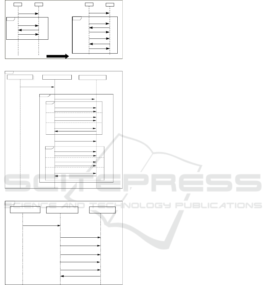
We call hidden relations the relations between the
events of LOOP operand of the current iteration and
the events of the previous iterations (Fig.5). These
relations appear when the LOOP operand is flatten at
least one time. Hence, the necessity of defining a new
relation <
hcaus
in which we express the constraints of
precedence between the events of the current iteration
and the events of the previous iteration. In order to
compute the hidden precedence relations, we propose
the following steps: we flatten the LOOP operand only
once whatever is the number of iterations; we obtain
an intermediate sequence diagram SD’.
In SD’, we rename the operands as well as the
events of the second iteration with the same name
as those of the preceding iteration by labelling them
with a single quote (Fig. 6). We define the set EV T
0
to represent the events of the next iteration. <
0
RE
and <
0
EE
are respectively the reception-emission, and
the emission-emission relationships associated to the
SD’.
In an SD we can have several LOOP operand that
can be sequenced or nested. In this case, the same
processing is applied by computing for each LOOP
operand its hidden relationships; we note <
hcausX
, the
hidden relations of a given LOOP operand named X.
The formalization of the hidden relationships for a
LOOP operand X is given as follows.
<
hcausX
= {(e,e
0
)|e ∈ EV T ∧ e
0
∈ EVT
0
∧
(e,e
0
) ∈<
0
RE
∨(e,e
0
) ∈<
0
EE
}
Illustration1: consider the SD’ (depicted in Fig. 5),
in the first iteration, the preceding event of !m2 is
!m1, the preceding events of !m3 are ?m1 and ?m2.
In the second iteration, the preceding event of !m2
0
is !m4, the preceding events of !m3
0
are ?m4 and ?m2
0
.
Illustration2: as we aforementioned, for an ALT CF,
only one operand must be executed, hence it is in-
tuitive that the events that belong to distinct operands
must not be ordered, otherwise we have the deadlocks
of some events.
However, in some particular cases of nested struc-
ture, we can face a problem that the events of dis-
tinct operands of the same ALT CF (brother operands)
can have precedence relations. The Fig. 7 repre-
sents a possible execution of the SD (depicted in
Fig.6) containing nested CF. In the first iteration
of the LOOP CF, the first operand of the ALT CF
is executed; in the second iteration of the LOOP
CF, the third operand of the ALT CF is executed.
The event !view list o f participants, that belongs
to the third operand of the ALT CF, has among
its preceding events: i) the event ?delete session
that belongs to the same operand, ii) the events
?create calender session,?add training which both
belong to the first operand of the the ALT CF. Which is
problematic, since the events of brother operands are
not ordered. This justifies the renaming of the events
and the operands of the next iteration to prevent this
problem.
A Causal Semantics for UML2.0 Sequence Diagrams with Nested Combined Fragments
53
SD'
SD
m1
[5]
loop
m4
m3
m2
m1
m4
m3
m2
m4
m3'
m2'
'
loop
L1
L2
L2
L1
Figure 5: Processing of an SD with LOOP CF.
SD2
Training officer
Custom page
Training page
loop
alt
[choice1]
[choice2]
[choice3]
update_ request
redirect3
add_training
create_calender_session
choose_training
update_session
delete_session
view_list_of_participants
alt
[choice1]
[choice2]
[choice3]
redirect3'
add_training'
create_calender_session'
choose_training'
update_session'
delete_session'
view_list_of_participants
Figure 6: Processing of an SD with Nested CF.
SD3
Training officer
Custom page
Training page
update_request
redirect3
add_training
create_ calender_ session
delete_session
view_list _of_participants
redirect3'
Figure 7: Possible execution of The SD of the Fig. 6.
In an SD we can have several LOOP operand that
can be sequenced or nested. In this case, the same
processing is applied by computing for each LOOP
operand its hidden relationships; the entire hidden
relation is the union of the hidden relations of each
LOOP operand. Now, the causal relationships is com-
puted as follows.
<
caus
=<
SY NC
∪ <
RE
∪ <
EE
∪ <
hcaus
That means the ordering of events depends on the
cumulative rules of the relationships. The valid traces
are those which can be generated satisfying these or-
ders.
The defined rules (<
RE
, <
EE
, <
hcaus
) may be ap-
plied to the standard semantics by restoring the con-
straints that we relaxed. In the same way, these rules
can be adapted for any kind of semantics by strength-
ening or weakening some constraints.
5.2 Behaviour of Sequence Diagrams
The behaviour of a given SD is a set of traces. The
trace is a set of events occurrences. The occurrence
of an event depends on its definition.
5.2.1 The State of an Event
The causal semantics (O.Tahir and J.Cardoso, 2005)
deals only with basic SD. In the standard semantics,
even the UML2.0 SD, that are equipped with CF, are
treated as basic SD, since the standard recommends
their flattening. An event which belongs to a basic
SD can have two obvious basic states: executed or not
yet executed. In our approach, we support sequence
diagrams with sequential CF that can be nested. The
basic states are not sufficient to express the state of an
event in an SD with sophisticated structures (nested
CF). Indeed, each event in such SD can be: not yet
occurred, occurred, consumed one or several times.
Then, the variable state is defined as follows.
state : EV T → NAT
The state of an event is decreased whenever it is oc-
curred or ignored. To describe the state of an event e,
we use the following vocabulary:
• not yet occurred: when state(e) = weight(e),
• occurred: if the event e is executed or ignored one
or several times and 0 < state(e) < weight(e),
• consumed: when state(e) = 0.
During its execution, an SD can be in one state among
the following states:
• an initial state, when all its events are not yet oc-
curred,
• an intermediate state,
• a final state, when all its events are consumed:
state = EV T × {0}.
5.2.2 The Definition of an Event
The behaviour of an SD is the occurrence of its events.
An event occurs under some conditions and produces
some effects. Each event which belongs to SD with
combined fragment has triggers conditions including
ENASE 2017 - 12th International Conference on Evaluation of Novel Approaches to Software Engineering
54

causality with other events, require formalizing the
computation of events preceding the current event,
and execution effects.
The textual description of the definition an event
in a given SD with nested CF is done as follows.
Triggers conditions consist in checking that: i) the
precedents events of the current event are occurred
(executed or ignored), ii) the current event is not yet
consumed.
Execution effects consist in: i) updating the state
of the event.
6 RELATED WORKS
Most of existing semantics that are proposed for
UML2.0 SD are based on the definitions of the stan-
dard semantics for the computation of traces of an
SD, thus they are not suitable for SD modelling be-
haviours of distributed systems.
This mismatch has motivated the work
of (Sibertin-Blanc and J., 2005), (O.Tahir and
J.Cardoso, 2005) who proposed a causal semantics
for basic SD. In (Sibertin-Blanc and Tahir, 2006),
to show the benefits and the adequacy of causal
semantics for SD modelling distributed systems, the
authors present three kinds of semantics: emission
semantics, linear semantics and message sequence
charts (MSC) semantics.
The linear semantics and the emission semantics
impose a restrictive rules for the ordering of the events
of the SD, and they are practicable only for a smaller
kind of SD modelling some kind of systems. The
linear semantics (Cardoso and Sibertin-Blanc, 2001)
permits to order all the messages of the considered SD
by imposing a total serialization of the emission and
the reception of the messages. The emission seman-
tics (Cardoso, Janette and Sibertin-Blanc, Christophe,
2002) imposes the total serialization of emission of all
the messages. The semantics of the MSC (Rudolph
et al., 1996), predecessors of the SD, suffers from am-
biguity of semantics interpretation (Alur et al., 1996).
In the authors show that it can exists some kind of
partial order between events that depend strictly on
the considered architecture (for instance, existence of
one or several FIFO queue for all the process...). The
different partial order defined are (i) visual order: it
corresponds to the order of the events as they appear
in the SD and that does not reflect the occurrence or-
der of the events during the execution of the system,
(ii) enforced order: it corresponds to the order of the
events that the underlying architecture can guarantee
to occur only in the specified order, and (iii) inferred
order: it is defined as the transitive closure of enforced
order.
In our work, we consider the causal semantics that
is founded on a partial order theory. The causal-based
order relation defined accounts for the precedence re-
lation between the events of an SD as far as all the
synchronization between lifelines are ensured by the
exchanged events, without the use of a global con-
troller or the addition of other messages.
The presence of CF causes difficulties for the
derivation of traces, to ease the processing of the
LOOP and the ALT CF, some works interpret these
CF similarly as in structured programming languages
which lead to the lose of some possible traces. In
(Hammal, 2006), (G
`
abor Huszerl, 2008), in order to
reduce the non-determinism of the ALT CF, the au-
thors transform it into an IF − T HEN − ELSE con-
struct. In (Hammal, 2006), the authors state clearly
that for the loop CF, they
88
prefer use strict sequenc-
ing rather than weak one to avoid a pathological case
of divergence in LOOP combination when using asyn-
chronous communication
00
. Similarly, in (Knapp and
Wuttke., 2006), the authors define a new CF SLOOP
that enforces strict sequencing between the iterations.
In our approach, we interpret the LOOP and ALT CF as
in the standard semantics, differently of the interpreta-
tion in the structured programming languages. More-
over, since the rules of causal semantics relaxed the
constraint of the ordering of the events on each life-
line, we obtain all possible traces for an SD modelling
behaviours of distributed systems.
Usually, the existing works neglect the issues re-
lated to the use of nested CF in an SD. Although their
use allows several complex scenarios that can be ag-
gregated in a single sequence diagram, an inherent
difficulty of the interpretation and the analysis of the
SD arises. The standard semantics (Object Manage-
ment Group, 2009) does not propose a meta-model
for nested CF. In the work of (Shen, 2013), the au-
thors propose a formal semantics based on the rules
of the standard semantics, and that is close to the tar-
get formalism (LTL) and complicated to apprehend.
Moreover, they consider UML2.0 SDs having finite
traces with LTL formalism, that represents basically
infinite traces.
In (G
`
abor Huszerl, 2008), the authors consider
conformance operators (ASSERT, IGNORE, CON-
SIDER and NEGATE, permitting to categorize the
traces as invalid or valid, ALT and PAR) CF, and they
aim to define rules that allow or prohibit the nesting
of these operators, by limiting the nesting level of CF
to two levels.
In (Hammal, 2006), the authors propose a formal
definitions for UML2.0 SD based on branching time
semantics and partial orders in a denotational style,
A Causal Semantics for UML2.0 Sequence Diagrams with Nested Combined Fragments
55

nevertheless the notion of nested CF is briefly men-
tioned, and no explicit formalization for them is pro-
posed.
7 CONCLUSION
In this paper, we first defined an intuitive formaliza-
tion, based on set theory and tree structure, of se-
quence diagrams equipped with combined fragments
that can be nested. The formalization can be adapted
for any kind of semantics. Then, we have extended
the causal semantics by redefining its rules in a syn-
thetic way. The new causal relationship allows to
compute all possible valid traces for SDs with nested
CF that model behaviours of distributed systems, by
avoiding the flattening of SD equipped with (ALT,
OPT, LOOP) CF, hence the compact syntactic repre-
sentation is preserved.
The proposed semantics can serves as basis for
the derivation of traces of UML2.0 SD, as well as
for the definition of an operational semantics that fa-
cilitates the analysis of the SD. Our approach is not
related to any target translation formalism and can
be implemented by any formal method for its veri-
fication, although it is already implemented, (Dhaou
et al., 2015), (Dhaou et al., 2016), by Event-B method
offering powerful tools (Rodin/Pro-B).
Meanwhile, we are extending our proposal to
cover other concepts like the gates and the state in-
variants which allow one to express more complex
behaviours and to cover other CF, in particular those
dedicated to model parallel behaviours and invalid be-
haviours. In addition, we currently study theoretical
properties that are derived from the proposed seman-
tics.
REFERENCES
Abrial, J.-R. (1996). The B Book. Cambridge University
Press.
Alur, R., Holzmann, G. J., and Peled, D. (1996). An An-
alyzer for Message Sequence Charts. In SOFTWARE
CONCEPTS AND TOOLS, pages 304–313.
Cardoso, J. and Sibertin-Blanc, C. (2001). Ordering Ac-
tions in Sequence Diagrams of UML. In 23rd Inter-
national Conference on Information Technology In-
terfaces, pages 3–14, J. Marohnica bb, 10000 Za-
greb, Croatia. University Computing Centre Uniersity
of Zagreb.
Cardoso, Janette and Sibertin-Blanc, Christophe (2002).
An Operational Semantics for UML Interaction: Se-
quencing of Actions and Local Control. Euro-
pean Journal of Automatised Systems, APII-JESA,
36(7):1015–1028.
Cengarle, M. V., Graubmann, P., Wagner, S., and M
¨
unchen,
T. U. (2005). Semantics of UML 2.0 Interactions with
Variabilities.
Dhaou, F., Mouakher, I., Attiogb
´
e, C., and Bsaies, K.
(2015). Extending Causal Semantics of UML2.0 Se-
quence Diagram for Distributed Systems. ICSOFT-EA
2015 - Proceedings of the 10th International Confer-
ence on Software Engineering and Applications, Col-
mar, Alsace, France, pages 339–347.
Dhaou, F., Mouakher, I., Attiogb
´
e, C., and Bsa
¨
ıes, K.
(2016). Refinement of UML2.0 Sequence Diagrams
for Distributed Systems. In Proceedings of the 11th
International Joint Conference on Software Technolo-
gies (ICSOFT 2016) - Volume 1: ICSOFT-EA, Lisbon,
Portugal, July 24 - 26, 2016., pages 310–318.
G
`
abor Huszerl, H
´
el
`
ene Waeselynck (ed.), Z. E. A. K.
Z. M. (2008). Refined Design and Testing Framework,
Methodology and Application Results.
Grosu, R. and Smolka, S. (2005). Safety-Liveness Seman-
tics for UML 2.0 Sequence Diagrams. In 5th Int.
Conf. on Application of Concurrency to System De-
sign, page 614.
Hammal, Y. (2006). Branching Time Semantics for UML
2.0 Sequence Diagrams. Lecture Notes in Computer
Science: Formal Techniques for Networked and Dis-
tributed Systems - FORTE 2006, pages 259–274.
Harel, D. and Maoz, S. (2008). Assert and Negate Revis-
ited: Modal Semantics for UML Sequence Diagrams.
Software and System Modeling, 7(2):237–252.
Knapp, A. and Wuttke., J. (2006). Model Checking of UML
2.0 Interactions. In Khne, T., editor, Models in Soft-
ware Engineering, pages 42–51. Springer.
Object Management Group (2009). OMG Unified Model-
ing Language (OMG UML), Superstructure Version
2.2.
O.Tahir, C.-B. and J.Cardoso (2005). A Causality-Based
Semantics for UML Sequence Diagrams. In 23rd
IASTED International Conference on Software Engi-
neering, pages 106–111. Acta Press.
øystein Haugen, Knut Eilif Husa, R. K. R. and STAIRS
(2005). Towards Formal Design with Sequence Di-
agrams. In Software and System Modeling, volume 4,
pages 355–357. John Wiley & Sons, Inc.
Rudolph, E., Grabowski, J., and Graubmann, P. (1996). Tu-
torial on Message Sequence Charts (MSC’96).
Shen, H. (2013). A Formal Framework for Analyzing Se-
quence Diagram. PhD thesis.
Sibertin-Blanc, C. and Tahir, O. (2006). From UML1.x
to UML 2.0 Semantics for Sequence Diagrams. In
Ramos, F. F., Lrios, R. V., and Unger, H., editors,
IEEE International Symposium and School on Ad-
vance Distributed Systems (ISSADS), Mexico (Mex-
ique). IEEE.
Sibertin-Blanc, C., T. O. and J., C. (2005). Interpretation of
UML Sequence Diagrams as Causality Flows. In Ad-
vanced Distributed Systems, 5th Int. School and Sym-
posium (ISSAD), number 3563, pages 126–140. Acta
Press.
ENASE 2017 - 12th International Conference on Evaluation of Novel Approaches to Software Engineering
56
