
Automatic Source Code Generation for Web-based Process-oriented
Information Systems
Jean Pierre Alfonso Hoyos and Felipe Restrepo-Calle
Department of Systems and Industrial Engineering, Universidad Nacional de Colombia, Bogot
´
a, Colombia
Keywords:
Fast Prototyping, Requirements, Natural Language Specification, Compilers, Software Construction Automa-
tion, Restricted Natural Language, Web Applications, BPMN.
Abstract:
Software development life cycle (SDLC) activities include: requirements analysis, design, development, test-
ing and maintenance. The first two steps have wide impact in the project success, and errors in these stages can
have large impact in the project duration and budget. To mitigate these problems, strategies like fast prototyp-
ing using natural language to specify software requirements have been proposed. These approaches can make
the SDLC faster. In this context, this paper presents an approach to automatically generate a web application
prototype running business processes using a restricted natural language specification. A comprehensive case
study is presented to validate the proposal and demonstrate its applicability.
1 INTRODUCTION
Requirements elicitation tasks can have errors due
to incompleteness or ambiguities in the requirements
(Walia and Carver, 2009). The designer’s lack of
knowledge about the customer business operation and
limited communication with the stakeholders can also
introduce errors in software (Walia and Carver, 2009;
Fairley, 2009). Errors in this early phase can have
large impact in the project duration and budget (Walia
and Carver, 2009).
To mitigate some of these problems, various
strategies like fast prototyping and agile software de-
velopment methodologies have been proposed (Au-
gustine and Martin, 2005). However, these agile
methodologies are more suitable for small teams and
small-scale value-oriented software projects, and left
behind big scale or mission critical software (Githens,
2006; Fowler and Highsmith, 2001). Moreover, fast
prototyping approaches attempt to make SDLC faster,
less sensible to human errors and less sensible to nat-
ural language inherent ambiguities and specification
incompleteness. Therefore, they can reduce produc-
tion costs, time to market delivery and prototyping
costs (Harris, 2012). Some examples of this fast pro-
totyping tools are: Bizzagi
1
, which uses graphical in-
teractions and specification languages to create an in-
formation system; Justinmind
2
that creates interactive
1
https://www.bizagi.com/
2
https://www.justinmind.com/
UI prototypes of mobile applications and web pages;
OpenXava
3
that creates a web application form a set
of java classes. In addition, other approaches use a
specification written in natural language (restricted or
unrestricted) to automate the construction of models
from texts (Ibrahim and Ahmad, 2010; Bhatia et al.,
2013). These approaches permit a fast validation of
the software and faster feedback from stakeholders
(Abbott, 1983; Nishida et al., 1991).
In this context, this paper presents an approach to
generate a web application prototype running busi-
ness processes automatically using a restricted natu-
ral language specification. This new language is pre-
tended to be used by a designer in a live meeting
with the stakeholders, showing the results of the pro-
totype as a mean to validate the requirements of the
software in a fast and interactive way. To achieve
this goal, a restricted natural language is proposed.
It is based on two different transformations between
well-known design models (E-R diagrams and BPMN
models) and natural language (English). In addition,
the expressiveness of the proposed language permits
to describe tasks to generate functional prototypes.
The main contributions of this paper are:
• A specification language for software require-
ments: restricted natural language.
• A fast prototyping method for web applications
running business processes using a restricted nat-
3
http://openxava.org
Hoyos, J. and Restrepo-Calle, F.
Automatic Source Code Generation for Web-based Process-oriented Information Systems.
DOI: 10.5220/0006333901030113
In Proceedings of the 12th International Conference on Evaluation of Novel Approaches to Software Engineering (ENASE 2017), pages 103-113
ISBN: 978-989-758-250-9
Copyright © 2017 by SCITEPRESS – Science and Technology Publications, Lda. All rights reserved
103

ural language specification.
This paper is structured as follows. The second
section describes the related works. The third sec-
tion presents our proposal. The fourth section shows
the implementation details. Later, the fifth section ex-
plores the results of a comprehensive case study. Fi-
nally, the sixth section summarizes some concluding
remarks and suggests the future works.
2 RELATED WORKS
Many work has been done on the software model ex-
traction from texts. Efforts have been focused on:
Design attributes mining from texts written in natural
language, the use of templates to write requirements,
and specification languages inspired by natural lan-
guages.
In the first case, the reviewed proposals are aimed
to extracting design information from textual specifi-
cations written in unrestricted natural language. (Ab-
bott, 1983) and (Saeki et al., 1989) originally pro-
posed manual procedures back in the 80’s. Words
in the description matching certain parts of speech
and phrase structures were used to build a model.
This procedure latter was extended and automatized
using natural language processing tools. Some gen-
eral steps of this method include: Stemming, POS
tagging, Sentence splitting, Resolve references and
anaphoras, use ontologies to determine implicit re-
lations, use wordnet to find synonyms and not ex-
plicit stated relations, rule based design information
extraction, and finally a production of a model (or
a set of models). Some works in this field include:
(Bellegarda and Monz, 2015; Cambria and White,
2014; Chioac, 2012; Overmyer et al., 2001). In this
way, (Desai et al., 2016) recently proposed a transfor-
mation framework between natural language to do-
main specific languages (DSLs) using machine learn-
ing techniques to generate a set of possible programs.
This approach facilitates to any person the de-
scription of the desired functionality of software.
Even with a few writing errors, information still can
be used (Ibrahim and Ahmad, 2010). In the down-
side, it is necessary some predefined knowledge (On-
tologies, Wordnet) in order to properly extract rela-
tions between terms (Popescu et al., 2008). Some-
times a training data set (Bellegarda and Monz, 2015)
and/or a set of ontologies (Zhou, X; Zhou, 2008)
might be needed to achieve acceptable results. More-
over, current NLP tools can be imprecise leading to
induce misinterpretations of the specification (Belle-
garda and Monz, 2015). In addition, this method is
the slowest of the three approaches due to its high pro-
cessing requirements (Bellegarda and Monz, 2015).
Secondly, many have tried to restrict the way re-
quirements are written using templates. In this way,
key design information can be easily extracted from
requirements lists to generate a model or a software
prototype (Smith et al., 2003; Konrad and Cheng,
2005; Zapata, 2006; Videira et al., 2006; Ili
´
c, 2007;
Zeaaraoui et al., 2013; Dahhane et al., 2015).
Although using templates to write the specifica-
tion of the software is more difficult, when done, is
as easy to understand by the stakeholders as in the
first approach (Selway et al., 2015). The use of tem-
plates facilitates processing tasks, making this ap-
proach faster than the first one. However, its main dis-
advantage is that designers must be very careful writ-
ing requirements or some information may be lost. It
is necessary to define each template in order to extend
the proposed solution, and requirements not match-
ing any template will be discarded leaving informa-
tion outside of the final model (Granacki and Parker,
1987).
Lastly, restricting the grammar of a natural lan-
guage such as English, can lead to overcome the am-
biguity and imprecision of such languages. For in-
stance, Attempto (Schwitter, 1996) is an executable
specification language in which the English grammar
is restricted. In this way, writing requirements is very
similar to work with a programming language, which
avoids ambiguities and facilitates the processing ef-
fort (Bryant and Lee, 2002). Nonetheless, having
to learn an artificial language is an inconvenient for
the designers and the stakeholders (Schwitter, 1996).
This approach is slower generating code than the sec-
ond but faster than the first one.
This paper proposes the use of templates within
the context of an specification language, this is, a hy-
brid between the second and the third approaches ex-
plained before.
3 FAST PROTOTYPING OF WEB
APPLICATIONS RUNNING
BUSINESS PROCESSES
This work proposes a fast prototyping method for
web applications running business processes using a
restricted natural language specification. To do so,
we use the model-view pattern, implementing a set
of business processes operating over a set of domain
classes, using only the restricted specification.
Fig. 1 presents a general schema of the proposed
workflow. Firstly, during a live meeting with stake-
ENASE 2017 - 12th International Conference on Evaluation of Novel Approaches to Software Engineering
104
holders, a designer writes down a software specifica-
tion using the restricted English grammar, which is
proposed in this paper (restricted natural language).
Although the specification in restricted natural lan-
guage could be understood by a non-technical user,
the target user of the proposed method is a designer
with technical background. This is needed because
the relations and concepts expressed with the re-
stricted language are not easy to understand to a non-
technical stakeholder. Secondly, our code generation
engine produces the source code of the web applica-
tion. Finally, the stakeholders are able to see and val-
idate the generated application prototype. If a modi-
fication is required then the specification is changed,
the code is generated and validated again in an iter-
ative way. In this way, it is possible to obtain direct
feedback from the stakeholders and achieve fast vali-
dation of the software.
Live Protoyping Meeting
Designer
Code Generation
Tool
Stakeholder Group
Generate
Source Code
Write
Specification
Run Generated
Protoype
Comunicate
Requirements
Does The
Protoype Meets
Prototypable
Requirements?
Validate
Prototype
No
Yes
Figure 1: General workflow proposed for fast prototyping
of web applications.
3.1 Restricted Natural Language
To work with a restricted natural language to generate
web application prototypes without human interven-
tion, we focus only on the English constructs of inter-
est for this task. To do so, we first consider two dif-
ferent transformations from commonly used software
design models, i.e. E-R diagrams and BPMN models,
to a restricted natural language. Next, we build a lan-
guage capable of defining the operations and combine
the previous two specifications.
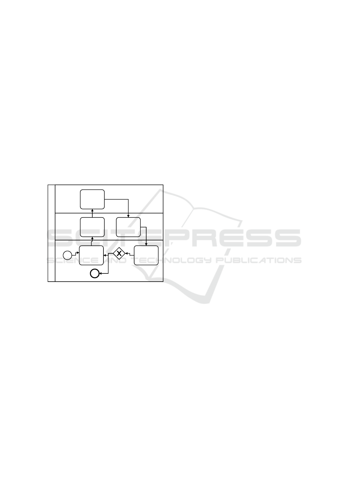
BPMN is a graphical specification language de-
signed to show the flow of activities, decisions and
events that occur in an organization in order to gener-
ate some form of business value.
Let b be a well constructed BPMN model, and
let f (b) a function that maps b to source code (s
1
);
now let t
1
be a restricted natural language specifica-
tion such that g(t
1
) = b, where g is a function trans-
forming the input text t
1
into a BPMN model (Equa-
tions 1 and 2). The proposed functions can be seen as
a generalization of several works such as (Friedrich
et al., 2011; Steen et al., 2010).
f (b) = s
1
(1)
g(t
1
) = b (2)
Moreover, E-R diagrams are graphical specifica-
tions that model the relationships between informa-
tion entities within a system and the information con-
tents of each one of these entities.
Similarly, let e be a well constructed E-R model,
h(e) a function that generates source code (s
2
); and let
t
2
be a restricted natural language specification such
that j(t
2
) = e, where j is a function transforming t
2
into an E-R model (Equations 3 and 4). These func-
tions can be seen as a generalization of works like
(Geetha and Mala, 2013; Meziane and Vadera, 2004;
Geetha and Anandha Mala, 2014).
h(e) = s
2
(3)
j(t
2
) = e (4)
In this way, evaluation of functions f (g(t
1
)) and
h( j(t
2
)) will return source code from the restricted
natural language specification. Note that t
1
and t
2
could also be unrestricted specifications, and the pre-
vious reasoning still applies. However, for the pur-
poses of this paper, we will restrict the natural lan-
guage constructs to avoid ambiguities and different
context-dependent interpretations.
Suppose that a pair of functions g
−1
(b) and j
−1
(e)
exists (e ∈ E − R, b ∈ BPMN), meaning that there
is a projection of the design models into natural lan-
guage (Equations 5 and 6). The construction of these
functions can be viewed as a ”design” process starting
from the model space to the natural language space.
g
−1
(b) = t
1
(5)
j
−1
(e) = t
2
(6)
These projections are not unique, but some subset
of natural language can be selected in a way that is not
ambiguous and can be used to transform both models
to a single common representation: restricted natural
language.
Having both models in the same space, it is pos-
sible to combine them in a way that exceeds the
code generation capabilities of both models sepa-
rately. Moreover, in this case we will introduce a set
of task definition non terminals and integrate those
with the previously defined specifications. In ad-
dition, with no ambiguity restrictions, a traditional
Automatic Source Code Generation for Web-based Process-oriented Information Systems
105

terminal FID :
’ˆ’?(’A’..’Z’|’_’) (’a’..’z’|’A’..’Z’|’_’|’0’..’9’)*;
Identifier : parts+=FID (parts+=FID)*;
DefinitionItem: arity=(’a’|’an’|’many’) specName=Identifier
’named’ intanceName=Identifier ’with’
defaultName=Identifier ’as’ ’default’;
Definition: childname=Identifier ’is’ ’an’ specName=Identifier
(’which’ ’exist’ ’in’ contextName=Identifier)?
’and’ ’needs’ ’:’ definitions+=DefinitionItem
(’,’ definitions+=DefinitionItem)* ’.’;
Figure 2: Grammar for the restricted natural language rep-
resenting E-R diagrams.
parser can be used to process the natural language
specification.
It is worth mentioning that unrestricted natural
language is not used because the process described in
section 2 will induce errors or generate more than one
system (Desai et al., 2016), making hard to validate
every possible system.
3.1.1 From E-R Diagrams to Restricted Natural
Language ( j
−1
(e))
To achieve a textual representation of an E-R model,
we propose to restrict the natural language constructs
as follows.
To define an entity an entity name (childname) is
required. Also a set of relations and a set of proper-
ties (DefinitionItem) are defined. Note that the entity
name can be in singular and plural forms, thus need-
ing a mechanism to identify them both as the same
noun. Fig. 2 shows the excerpt of the proposed gram-
mar for the domain classes. It can be used to gener-
ate a class diagram including properties, and relation-
ships.
Furthermore, notice that some defaults should be
configured including both data types and their respec-
tive memory size. For instance, properties having a
VARCHAR data type are assumed to be maximum of
255 in length.
3.1.2 From BPMN to Restricted Natural
Language (g
−1
(b))
In order allow our restricted natural language to rep-
resent business processes, we propose to use the fol-
lowing BPMN textual representations. Note that these
representations include the most common BPMN
constructs. Figure 3 shows the mappings from a
BPMN element to BNF rule written in Xtext
4
format.
Note that for the gateway and frontier event el-
ements the rule is spitted in two parts: one defined
within task list rule and another defined in a separated
paragraph. This allows the specification to take more
than a paragraph. Finally note that returning to a pre-
4
http://www.eclipse.org/Xtext/
viously defined task is done with a special rule ”go
back to”.
//------Process and Start Event------
Tasklist: taskList+=Asignedtask ((’,’ taskList+=Asignedtask)*
’and,’ taskList+=Asignedtask)? ’.’;
Process: ’the’ name=Identifier ’process’ ’starts’ ’,’ ’then’
’:’ taskList=Tasklist;
//------End Event------
EndEvent: ’the’ ’process’ name=’ends’;
//------Tasks------
SimpleTask: name=Identifier;
GotoJump:’go’ ’back’ ’to’ returnTo=Identifier;
Task:task=(SimpleTask|AfterEvent|WaitSignalEvent|
WaitMessageEvent|GotoJump|EndEvent|SubprocessendEvent|
SubprocessCall|JumpToAsk|QuestionRedirect|EventRedirect|
ParallelRedirect);
//------Exclusive Gateways------
QuestionRedirect: ’ask’ ’if’ redirectTo=Identifier;
QuestionControl : ’if’ ’the’ ’answer’ ’to’
questionName=Identifier ’is’ answer=FID ’then’ ’:’
taskList=Tasklist ;
//------Parallel Gateways------
ParallelRedirect: ’do’ ’at’ ’the’ ’same’ ’time’
’the’ redirectTo=Identifier ’tasks’;
ParallelControl: ’for’ redirectName=Identifier ’tasks’
(’also’)? ’do’’:’ taskList=Tasklist;
//------Event Gateways------
EventRedirect: ’check’ ’the’ redirectTo=Identifier ’event’;
EventControl : ’if’ ’the’ ’event’ eventName=Identifier ’is’
eventCatched=Identifier (’signal’|’message’|’timer’)
’then’ ’:’ taskList=Tasklist ;
//------Subprocess------
SubprocessCall:’the’ subprocessName=Identifier ’is’ ’made’;
Subprocess: ’the’ name=Identifier ’subprocess’ ’starts’ ’,’
’then’ ’:’ taskList=Tasklist;
//------Events------
WaitMessageEvent:’wait’ ’for’ ’the’ messageName=Identifier
’message’;
AfterEvent:’wait’ duration=INT
unit=(’week’|’weeks’|’hour’|’hours’|’minutes’|
’minute’|’days’|’day’);
WaitSignalEvent:’wait’ ’for’ ’the’ signalName=Identifier
’signal’;
//------Lanes------
Asignedtask: task=Task (’(by’ asignee=Identifier ’)’)?;
//------Frontier events------
FronterEvent: ’if’ ’the’ name=Identifier
(’signal’|’message’|’timer’) ’arrives’ ’while’ ’doing’
task=Identifier (’stop’ ’it’|’wait’ ’to’ ’complete’)
’and’ ’then’ ’:’ taskList=Tasklist;
Figure 3: Element to rule mapping for BPMN.
3.1.3 Task Definition Language
Another part of the grammar involves the definition
of each task in each process to generate the views
and controllers for the desired system. This defini-
tion must involve some sort of operations in some of
the defined domain classes. This operation of course
must be one of the four CRUD (Create, Read, Update
or Delete) operations. In addition, two extra opera-
tions (”single selection” and ”multiple selection”) are
added. This operations solve problems like showing a
single instance (one must be selected beforehand) and
selecting a list of instances to operate over them.
Furthermore, operations like creation and edition
over multiple instances of the domain classes may be
useful. The grammar created to fulfill these require-
ments is shown in Figure 4.
Previous textual representations (E-R and BPMN
models) can be combined using this grammar frag-
ment. Here we use the domain classes information to
ENASE 2017 - 12th International Conference on Evaluation of Novel Approaches to Software Engineering
106
TaskRedefinition:taskName=Identifier ’is’ ’a’ ’task’ ’where’
’:’ partslist=ViewPartsList;
ViewPartsList: list+=AbstractOperation+;
AbstractOperation: operation=(Creation|MultipleView|
SingleView|FieldView);
FieldRestrictor : ’,’ ’only’ fields+=Identifier (’,’
fields+=Identifier)* ’are’ ’shown’;
Operations :’edition’|’deletion’|’multiple’ ’selection’|
’single’ ’selection’;
OperationAdition: ’,’ ’with’ permisions+=(Operations)
((’,’|’and’) permisions+=(Operations))* ’capabilities’;
Creation: ’-’ arity=(’multiple’|’a’) name = Identifier
(’are’|’is’) ’created’ (restriction=FieldRestrictor)? ’.’;
MultipleView: ’-’ ’all’ ’the’ child = Identifier
(’in’ parent = Identifier)? ’are’ ’shown’
(restriction= FieldRestrictor)?
(operations=OperationAdition)? ’.’;
SingleView : ’-’ ’a’ name = Identifier ’is’ ’shown’
(operations=OperationAdition)? ’.’;
FieldView : ’-’ ’the’ fields+=Identifier ((’,’|’and’)
fields+=Identifier)* ’in’ parent = Identifier ’are’ ’shown’
(operations=OperationAdition)? ’.’;
Figure 4: Grammar for task definition.
specify the data contained in the generated views and
actions to be performed in the controllers.
Overall, this restricted natural language permits to
specify not only structural information but also func-
tional requirements of the software. Thus, it allows
the designer to build a textual specification of the re-
quired software in conjunction with the stakeholders.
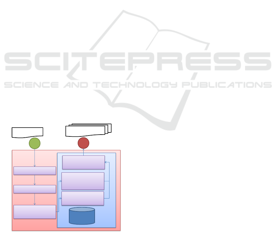
3.2 Code Generation Approach
After the software specification is written in restricted
natural language, the source code of the target web
application is generated as depicted in Fig. 5.
Code Generation
Parser
Design attributes
extraction
Domain classes and
Forms code
Process tasks
(views and
controllers) code
Code DB
Webapp template
placement
Lexer
Input .aku
WebApp code
Figure 5: Code generation process.
The input of the code generation process is a
file with the textual specification of the software (In-
put.aku). The first steps consist of traditional lexical
and syntactic analyses performed to the specification.
Next, the phase of design information extraction is
performed where the names of the parts of the sys-
tem are extracted. Then, this information is used to
generate source code for the web application.
The source code generation is aided using a
database containing the source code of previously de-
fined specifications. This specifications can include
definitions of the process helper views and tasks. Also
can include code to generate the domain classes, in-
put fields, HTML for the views and the final template
where the generated code is placed.
Thanks to the restricted natural language, the
lexer, parser, and payload extraction phases can be
performed using a traditional top-down parser, avoid-
ing the inherent ambiguity of natural languages.
After this processing, the code for the domain
classes and forms is created. To match expected re-
lationships, we check for the following cases: (1) an
attribute has a known data type; (2) an attribute ref-
erences another class in the specification; (3) a class
has an attribute of the form many; and (4) class has an
attribute of the form many and the another class has
the first class referenced back in other attribute of the
form many.
In the first case (1), we use the code database to
generate the desired field; in the second case (2), we
assign the data type of the attribute to a foreign key
referencing the class. In third case (3), we understand
this as an one-to-many relationship, thus, we alter the
referenced class inserting a foreign key attribute ref-
erencing the class that has a set of the other class.
Finally, for the fourth case (4), this is interpreted as
a many-to-many relationship, therefore, we insert an
additional table referencing the two involved classes
and the respective foreign keys in each class.
Next, the code for the process is generated. For
each task a template in the database is fetched and
resolved, if the controller generated needs a view the
file is generated also. If the task is a SimpleTask then
the following process is performed:
1. Check for the definition in other paragraph of the
specification
2. If the definition exist then resolve the controller
and view code.
3. If its not defined use a default controller and view.
This SimpleTask definition methods use the
”TaskRedefinition” non terminal to generate the code
for its view and controller. It uses code fragments de-
fined in the database to generate only the needed code
to query, update, create or delete the domain classes
instances.
Automatic Source Code Generation for Web-based Process-oriented Information Systems
107

In addition, we decided that a process control
method is needed. This method will take the current
task and determine the next based on the workflow
defined in the TaskList non-terminals across the para-
graphs in the specification. This method will help to
resolve the gateways using the input given by the user
in the generated view or the events registered. It also
will help to determine the behavior of the tasks se-
quence related to cached frontier events.
The code for the exclusive gateways will be a
method where a snippet of HTML is rendered ask-
ing the defined question. Then, after a POST request
to a controller, use the previously defined controller
method do determine the task to be done next.
Finally, these pieces of code are placed in a tem-
plate prepared to execute the web application as de-
sired in the specification.
4 IMPLEMENTATION
To implement the proposed solution we should make
first a separation between the process to get the web
application and the application itself. Both of them
use different languages and tools to execute its re-
quired tasks. For the process we use a set of java
based tools and for the result we use a set of python
based ones.
For the process of generating the web application
we used the Xtext
5
toolkit including the Xtend lan-
guage, adding a database of specifications and code
templates using SqlLite and a micro ORM framework
called OrmLite
6
. Code templates are created using
the Freemarker
7
engine.
According to the process illustrated in Fig. 6,
which is the specialization of the general code gen-
eration process shown in Fig. 5. We use Xtext to gen-
erate the lexical analyzer, the parser, and the design
information extractor. We implement the previously
shown grammars. Also, Xtext creates a set of classes
containing the required design information from each
rule.
Prior to generate code for domain classes the ref-
erences in its arguments are resolved first determining
the case they belong as described previously in this
paper. Notice that it is necessary to take into account
the respective transformations between the plural and
singular forms of the nouns (entity names). This can
be done having a predefined set of rules and a dictio-
nary for irregular nouns.
5
http://www.eclipse.org/Xtext/
6
http://ormlite.com/sqlite java android orm.shtml
7
http://freemarker.org/
Code Generation
Xtext lexer, parser
and design
information
extraction
Sql Alchemy classes
Python Control method generation
Code DB
Webapp
template
placement
Input.aku
WebApp
code
Jinja views and Flask controllers
Wtforms Forms
Figure 6: Implementation work flow.
When the references are determined, a set of pre-
viously written code templates is used to transform
the design information into the target code. For the
entities a SQLalchemy
8
(an ORM system) class, and
also to class in a WTForms
9
(a web forms processor).
Note that more than one code fragment can be gener-
ated in one template.
After this code is ready, the views and controller
methods for each task are created. Again using tem-
plates (but this time several of them), we generate
code for each of the non-terminals that are option of
the non-terminal ”Task”.
For most of these elements a simple template re-
placement formula is enough. For instance, the tem-
plate for ”go back to” tasks is shown in Figure 7.
@app.route(
’/${r"${procesname}"}/<pid>/redirect/
${data.returnTo.asMethodName()}’, methods=[’GET’]
)
def ${r"${procesname}"}_redirect_$
{data.returnTo.asMethodName()}(pid):
return
redirect(${r"${procesname}"}_resolve_next_task(
request.url_rule,pid,None
)
)
Figure 7: “Go back to” code template example.
The process of generating a view changes if there
is a redefinition for a ”SimpleTask” non-terminal.
Then the process uses the information given in the
”TaskRedefinition” non-temrinal. It uses the informa-
tion within its parse tree to determine the code result
in both controller and view. To do this we use tem-
plates to generate partial results of the source code of
the method and then merging them in a helper tem-
plate.
8
http://www.sqlalchemy.org/
9
https://wtforms.readthedocs.io/
ENASE 2017 - 12th International Conference on Evaluation of Novel Approaches to Software Engineering
108

Moreover, there must be templates used to gener-
ate edition controllers with or without selections and
only to show previously created elements. Following
the same idea we use templates to create the HTML
template that the web application needs as UI.
Also we iterate over the ”Process” non-terminal
instances again to create the helper method. This
task is done with recursive calls of the ”Tasklist” non-
terminal within the process and gateway definitions.
It generates a single method which takes as an input
the URL of the current task and returns the next task.
After all the source code is generated, using the
same template system, the resultant strings are placed
directly into a web application template assuming that
the needed imports and dependencies are resolved.
The template system used for the result web ap-
plication was Jinja2
10
. Moreover, a small database in
SQLite3
11
is used to deploy and test the result of the
proposed method.
In summary, the tool chain used for the imple-
mentation of our proposal is comprised of: Program-
ming languages: Python 2.7, Xtend; Parser generator:
Xtext; Template systems: Jinja 2, Freemarker; Web
framework: Flask; ORM systems: SqlAlchemy, Orm-
Lite; Web forms processor: WTforms; HTML, CSS,
and JS framework for developing responsive applica-
tions on the web: Bootstrap
12
, and the SB Admin 2
Bootstrap
13
admin theme; Database: SQLite3.
5 RESULTS AND DISCUSSIONS
In order to validate and demonstrate the applicability
of the proposal, this section includes the presentation
of the results of a case study, and the comparison of
this work to related works. The case study is titled:
Odoo Sales Clone.
5.1 Case Study: Odoo Clone
Odoo
14
is an open ERP and CRM system. For the
purpose of this work, some modules of this system are
developed using our restricted language. The selected
modules are: sales and projects. The selected version
of Odoo is 9.0.
The sales module has 5 processes. Each one of
them consists in a couple of tasks. There are three cre-
ation processes including: Client, Opportunity, and
10
http://jinja.pocoo.org/docs/dev/
11
https://www.sqlite.org/
12
getbootstrap.com/
13
https://startbootstrap.com/template-overviews/sb-
admin-2/
14
https://www.odoo.com/
Product; and two additional processes to list opportu-
nities and products, and select and edit them.
The project module consists in a series of projects,
each one with a set of associated tasks. Also there are
processes for the selection, presentation, and creation
of tasks and projects.
The resultant software requirements can be speci-
fied using the restricted natural language as follows:
Language is an Domain Class and needs: a String named Name.
Contact Type is an Domain Class and needs: a String named
Type.
Contact is an Domain Class and needs: a Contact Type named
Type, a String named Name, a String named Address, a String named
Address2, a String named City, a String named State, a Number
named Zip Code, a String named Country, a Website named Home-
page, a String named Work Desk, a Phone named Personal Phone, a
Phone named Mobile Phone, a Phone named Fax, a Email named Per-
sonal Email, a String named Title and a Language named Language.
User is an Domain Class and needs: a String named Name and
an Email named Username.
Sales Team is an Domain Class and needs: a String named Name,
a Number named Code and a User named Team Leader.
Activity is an Domain Class and needs: a String named Message
Type, a Number named Number Of Days and a Sales Team named
Assigned Sales Team.
Opportunity State is an Domain Class and needs: a String named
Name.
Opportunity Phase is an Domain Class and needs: a String named
Name.
Opportunity is an Domain Class and needs: a String named De-
scription, a Number named Income, a Number named Probability,
a Contact named Client, an Activity named Next Activity, an Email
named Contact Email, a Phone named Contact Phone, a Date named
Provided Closing, a User named Seller, a Sales Team named Respon-
sible Sales Team, a Number named Rating, an Opportunity Phase
named Phase and a Opportunity State named State.
Product Type is an Domain Class and needs: a String named
Name.
Product is an Domain Class and needs: an Image named Photo, a
String named Name, a Product Type named Type, a String named Bar
Code, a Number named Price and a Number named Cost.
Project State is a Domain Class and needs: a String named Name.
Project is a Domain Class and needs: a String named Name, a
String named Task Label, a Contact named Client and a Project State
named State.
Task is a Domain Class and needs: a String named Name, a
String named Description, a Date named Limit Date, a User named
Assigned and a Project named Project.
the Client Creation process starts, then: Create Contact and, the
process ends.
Create Contact is a task where: -a Contact is created.
the Opportunity Creation process starts, then: Create Opportu-
nity and, the process ends.
Create Opportunity is a task where: -a Opportunity are created.
the Opportunity List process starts, then: Show Opportunities,
Show Opportunity and, the process ends.
Show Opportunities is a task where: -all the Opportunity are
shown, with single selection capabilities.
Automatic Source Code Generation for Web-based Process-oriented Information Systems
109

Show Opportunity is a task where: -a Opportunity is shown, with
edition capabilities.
the Product List process starts, then: Show Product List, Product
Detail and, the process ends.
Show Product List is a task where: -all the Products are shown,
only Name, Price are shown, with single selection capabilities.
Product Detail is a task where: -a Product is shown.
the Product Creation process starts, then: Create Product and, the
process ends.
Create Product is a task where: -a Product is created.
the Project Creation process starts, then: Create Project and, the
process ends.
Create Project is a task where: -a Project is created.
the Project List process starts, then: List Projects, Show Selected
Project and, the process ends.
List Projects is a task where: -all the Projects are shown, with
single selection capabilities.
Show Selected Project is a task where: -a Project is shown. -all
the Tasks in Project are shown.
the Task Creation process starts, then: Create Task and, the pro-
cess ends.
Create Task is a task where: -a Task is created.
the Task List process starts, then: List Tasks, Show Task and, the
process ends.
List Tasks is a task where: -all the Tasks are shown, with single
selection capabilities.
Show Task is a task where: -a Task is shown, with edition capa-
bilities.
Resulting in a set of views linked as shown in Fig.
10. These views contain the creation processes and
the two selection and posterior detail processes.
As an example of the generated code, the con-
troller for the “Show Selected Project” task is shown
in Fig. 8. This controller renders the view shown in
Fig. 9, which is also a template written to be com-
patible with the Jinja2 template system. In this view
each of the fields of the “project” domain class and all
the “tasks” associated with the selected “project” are
shown.
@app.route(’/projectList/<pid>/showSelectedProject’,
methods=[’GET’,’POST’])
def projectList_showSelectedProject(pid):
viewparams={}
data = get_instance_data(pid)
formdata = request.form.copy()
for file in request.files:
formdata[file] = request.files[file].filename
request.form = formdata
project = session.query(Project).filter(
Project.id==data.get("selected_Project",0)
).first()
viewparams[’project’]=project
task_list = session.query(Task).filter(
Task.project_id==data.get(’selected_Project’,0)
).all()
viewparams[’task_list’]=task_list
Figure 8: Example of a generated controller.
<div class="panel-heading">Show Selected Project</div>
<div class="panel-body">
{% for field in project.__table__.columns._data.keys()%}
<div class="form-group">
<b>{{field}}</b><br /> {{project[field]}}
</div>
{% endfor %}
<div class="col-lg-12">
<div class="table-responsive">
<table class="table">
<tr>
{% for prop in task_list[0].__mapper__.columns.keys() %}
<th>{{prop}}</th>
{% endfor %}
</tr>
{% for ent in task_list %}
<tr>
{% for prop in ent.__mapper__.columns.keys() %}
<td>{{ent[prop]}}</td> {% endfor %}
</tr>
{% endfor %}
</table></div></div></div>
Figure 9: Example of a generated view.
Some of the limitations of the generated prototype
include: the card-like layout of Odoo is lost in the
transcription, the same happens with its state based
card list; the images of the products are not shown but
they are uploaded; the project labels and their auto-
complete field are omitted; and the labels of the form
fields are not configurable without editing the source
code.
On the other hand, the fast processing of the
specification and its prototype generation allows the
stakeholders to see within seconds changes made to
the project. The textual specification permits to the
designer a rapid specification and its corresponding
validation after learning the restricted language con-
structs. Results can be seen in short time after a live
meeting starts with the stakeholders, and changes to
specifications at this stage are painless and economic.
Furthermore, some tools like auto-completion, high-
light syntax, and IDE integration can be used to make
this process even easier.
5.2 Comparative to Similar Works
Table 1 presents a comparative of related works, in-
cluding this proposal. The Table includes the main
differences with respect to the starting point of the
proposal, i.e., templates, (un)restricted natural lan-
guage, or specification language. It also includes the
final result of each work, e.g., executable program,
UML models, E-R diagrams, etc.
One can see that most related works manage some
form of natural language as starting point for the pro-
cess. Most of the works end up with a model con-
ENASE 2017 - 12th International Conference on Evaluation of Novel Approaches to Software Engineering
110
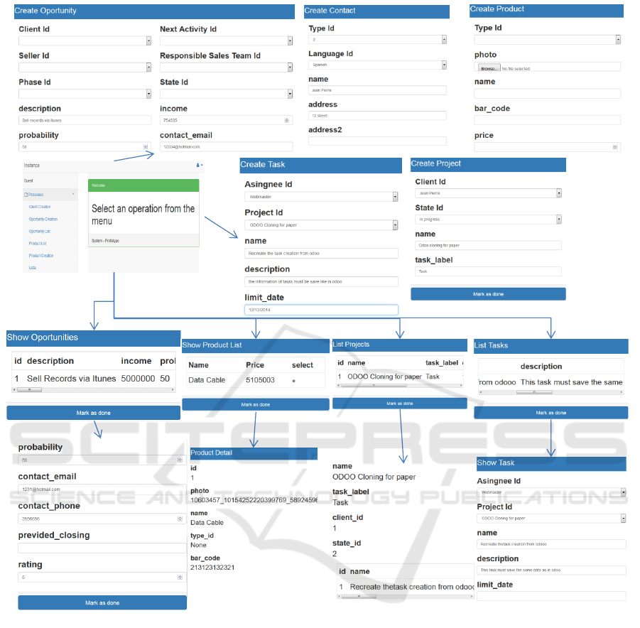
Figure 10: Odoo clone result views.
structed in some specification language like BPMN,
UML (some subset of the possible diagrams), or E-
R. Further translations are limited for external tools
like Rational Rose or Visual Paradigm. Some of the
works also need a manual intervention of the user to
select the design attributes. In this work, we obtain
a working prototype closer to a final product without
intervention from the user or external software.
Only a few proposals obtain executable programs
as an output. Among them, the work in (Abbott,
1983) involve a manual process, and the proposal in
(Schwitter, 1996) requires to work with previously
defined code fragments in order to obtain a command-
line based program. Contrarily, in the proposed ap-
proach, the result is an executable web application
prototype.
6 CONCLUSIONS
This paper presented a fast prototyping method for
web applications running business processes using a
restricted natural language specification. Two differ-
ent transformations were proposed between design
models (E-R diagrams and BPMN models) and nat-
ural language (English) to propose a new specifica-
tion language (restricted natural language). The pro-
posed transformations based on previous specification
languages maintain the expressiveness of the original
Automatic Source Code Generation for Web-based Process-oriented Information Systems
111

Table 1: Comparison to related works.
Work Start point Result
(Schwitter, 1996) Specification lan-
guage
Executable
(Deeptimahanti and
Sanyal, 2011)
Unrestricted natural
language
UML diagrams
(Friedrich et al.,
2011)
Unrestricted natural
language
BPMN diagram
(Liu et al., 2004) Templates UML class and se-
quence diagrams
(Abbott, 1983) Unrestricted natural
language
ADA Executable
(manual process)
(Geetha and Mala,
2013) (Geetha and
Anandha Mala,
2014)
Unrestricted natural
language
E-R diagram
(Popescu et al.,
2008)
Templates UML class diagram
(Chioac, 2012) Unrestricted natural
language
OSMs
(Overmyer et al.,
2001)
Unrestricted natural
language
UML class diagram
(Desai et al., 2016) Unrestricted natural
language
DSLs
This Work Restricted natu-
ral language +
Templates
Executable Web ap-
plication prototype
languages in the new representation. The use of this
new language permits to overcome limitations in tra-
ditional specification languages, improving the code
generation capabilities considerably.
This work opens up interesting paths for the au-
tomatic fast prototyping of web applications. How-
ever, there is more work to be done in the future.
This includes: to propose a sub-grammar/method for
automatic gateway resolution, and to extend the pro-
posed restricted natural language by including infor-
mation present in other design models besides E-R
and BPMN. Other limitations of the present work can
be addressed as well, such as: altering tasks execution
based on previous tasks; visualizations of data; ana-
lytics over the performed processes; geo-referencing
fields; fields with special visualizations; and special
restrictions in relationships between domain classes.
In exchange for these limitations, a fast prototyp-
ing scheme is obtained where results can be seen, ex-
ecuted, and altered in very short time allowing all of
this to occur during a live meeting with the stakehold-
ers. The changes made to the specification can be
seen instantly thanks to code generation capabilities
and IDE integrations. The final product of this proto-
typing scheme is a source code ready to be part of the
final product. This reduces the problems associated
with the requirements elicitation and design stages.
REFERENCES
Abbott, R. J. (1983). Program design by informal En-
glish descriptions. Communications of the ACM,
26(11):882–894.
Augustine, S. and Martin, R. C. (2005). Managing agile
projects. Robert C. Martin series. Prentice Hall Pro-
fessional Technical Reference, Upper Saddle River,
NJ.
Bellegarda, J. R. and Monz, C. (2015). State of the art in
statistical methods for language and speech process-
ing. Computer Speech & Language, 35:163–184.
Bhatia, J., Sharma, R., Biswas, K. K., and Ghaisas, S.
(2013). Using Grammatical knowledge patterns for
structuring requirements specifications. 2013 3rd In-
ternational Workshop on Requirements Patterns, RePa
2013 - Proceedings, pages 31–34.
Bryant, B. R. and Lee, B. S. (2002). Two-level gram-
mar as an object-oriented requirements specification
language. Proceedings of the Annual Hawaii In-
ternational Conference on System Sciences, 2002-
Janua(c):3627–3636.
Cambria, E. and White, B. (2014). Jumping NLP Curves:
A Review of Natural Language Processing Research
[Review Article]. IEEE Computational Intelligence
Magazine, 9(2):48–57.
Chioac, E. V. (2012). Using machine learning to enhance
automated requirements model transformation. Pro-
ceedings - International Conference on Software En-
gineering, pages 1487–1490.
Dahhane, W., Zeaaraoui, A., Ettifouri, E. H., and Bouchen-
touf, T. (2015). An automated object-based approach
to transforming requirements to class diagrams. 2014
2nd World Conference on Complex Systems, WCCS
2014, pages 158–163.
Deeptimahanti, D. K. and Sanyal, R. (2011). Semi-
automatic generation of UML models from natural
language requirements. Proceedings of the 4th In-
dia Software Engineering Conference on - ISEC ’11,
pages 165–174.
Desai, A., Gulwani, S., Hingorani, V., Jain, N., Karkare, A.,
Marron, M., R, S., and Roy, S. (2016). Program syn-
thesis using natural language. In Proceedings of the
38th International Conference on Software Engineer-
ing, ICSE ’16, pages 345–356. ACM.
Fairley, R. E. (2009). Managing and leading software
projects. IEEE Computer Society ; Wiley, Los Alami-
tos, CA : Hoboken, N.J.
Fowler, M. and Highsmith, J. (2001). The agile manifesto.
Software Development, 9:28–35.
Friedrich, F., Mendling, J., and Puhlmann, F. (2011). Pro-
cess Model Generation from Natural Language Text.
Lecture Notes in Computer Science, 6741:482–496.
Geetha, S. and Anandha Mala, G. S. (2014). Automatic
database construction from natural language require-
ments specification text. ARPN Journal of Engineer-
ing and Applied Sciences, 9(8):1260–1266.
Geetha, S. and Mala, G. (2013). Extraction of key at-
tributes from natural language requirements specifica-
tion text. In IET Chennai Fourth International Con-
ference on Sustainable Energy and Intelligent Systems
ENASE 2017 - 12th International Conference on Evaluation of Novel Approaches to Software Engineering
112

(SEISCON 2013), pages 374–379. Institution of Engi-
neering and Technology.
Githens, G. (2006). Managing Agile Projects by Sanjiv Au-
gustine. Journal of Product Innovation Management,
23(5):469–470.
Granacki, J. J. and Parker, a. C. (1987). PHRAN-SPAN: a
natural language interface for system specifications.
24th ACM/IEEE conference proceedings on Design
automation conference - DAC ’87, pages 416–422.
Harris, I. G. (2012). Extracting design information from
natural language specifications. Proceedings of the
49th Annual Design Automation Conference on - DAC
’12, page 1256.
Ibrahim, M. and Ahmad, R. (2010). Class diagram extrac-
tion from textual requirements using natural language
processing (NLP) techniques. 2nd International Con-
ference on Computer Research and Development, IC-
CRD 2010, pages 200–204.
Ili
´
c, D. (2007). Deriving formal specifications from in-
formal requirements. Proceedings - International
Computer Software and Applications Conference,
1(Compsac):145–152.
Konrad, S. and Cheng, B. H. C. (2005). Facilitating the
construction of specification pattern-based properties.
13th IEEE International Conference on Requirements
Engineering RE05, (August):329–338.
Liu, D., Subramaniam, K., Eberlein, A., and Far, B.
(2004). Natural language requirements analysis and
class model generation using UCDA. Innovations in
Applied Artificial Intelligence, pages 295–304.
Meziane, F. and Vadera, S. (2004). Obtaining E-R diagrams
semi-automatically from natural language specifica-
tions. pages 638–642.
Nishida, F., Takamatsu, S., Fujita, Y., and Tani, T. (1991).
Semi-automatic program construction from specifica-
tions using library modules. IEEE Transactions on
Software Engineering, 17(9):853–871.
Overmyer, S., Benoit, L., and Owen, R. (2001). Concep-
tual modeling through linguistic analysis using LIDA.
Proceedings of the 23rd International Conference on
Software Engineering. ICSE 2001, pages 401–410.
Popescu, D., Rugaber, S., Medvidovic, N., and Berry,
D. M. (2008). Reducing ambiguities in require-
ments specifications via automatically created object-
oriented models. Lecture Notes in Computer Science
(including subseries Lecture Notes in Artificial Intel-
ligence and Lecture Notes in Bioinformatics), 5320
LNCS:103–124.
Saeki, M., Horai, H., and Enomoto, H. (1989). Software
Development Process from Natural Language Speci-
fication. Proceedings of the 11th International Con-
ference on Software Engineering, pages 64—-73.
Schwitter, R. (1996). Attempto-from specifications in con-
trolled natural language towards executable specifica-
tions. Arxiv preprint cmp-lg/9603004.
Selway, M., Grossmann, G., Mayer, W., and Stumptner,
M. (2015). Formalising natural language specifica-
tions using a cognitive linguistic/configuration based
approach. Information Systems, 54:191–208.
Smith, R., Avrunin, G., and Clarke, L. (2003). From natu-
ral language requirements to rigorous property speci-
fications. Workshop on Software Engineering for Em-
bedded Systems (SEES 2003) From Requirements to
Implementation, pages 40–46.
Steen, B., Pires, L. F., and Iacob, M.-e. (2010). Automatic
generation of optimal business processes from busi-
ness rules. pages 117–126.
Videira, C., Ferreira, D., and Da Silva, A. R. (2006). A
linguistic patterns approach for requirements speci-
fication. Proceedings - 32nd Euromicro Conference
on Software Engineering and Advanced Applications,
SEAA, 2004:302–309.
Walia, G. S. and Carver, J. C. (2009). A systematic literature
review to identify and classify software requirement
errors.
Zapata, C. M. (2006). UN Lencep : Obtenci
´
on Autom
´
atica
de Diagramas UML a partir de un Lenguaje Contro-
lado. Memorias del VII Encuentro Nacional de Com-
putaci
´
on ENC’06, pages 254–259.
Zeaaraoui, A., Bougroun, Z., Belkasmi, M. G., and
Bouchentouf, T. (2013). User stories template for
object-oriented applications. 2013 3rd International
Conference on Innovative Computing Technology, IN-
TECH 2013, pages 407–410.
Zhou, X; Zhou, N. (2008). Auto-generation of Class Di-
agram from Free-text Functional Specifications and
Domain Ontology. (2):1–20.
Automatic Source Code Generation for Web-based Process-oriented Information Systems
113
