
Proposed Model of Street Lighting System based on OFDM
Operations for Smart Lighting
Mehdi Laraki and Aawatif Hayar
Smart City Team, RITM Laboratory, CED ENSEM, GREENTIC, Casablanca, Morocco
Keywords: Street Lighting System, Voltage Command, OFDM Techniques, Smart Lighting, Smart City.
Abstract: Abandoned for a very long time, because of the complexity of their Multi-Carrier techniques (Multi Carrier
Modulation, MCM or Orthogonal Frequency Division Multiplexing OFDM), nowadays, the OFDM has
become the strategic choice of several systems modern digital products. Its simplicity and flexibility, as well
as the transmission, make them particularly interesting for communication systems. Inspired from
Telecommunications field, especially from the OFDM Techniques, the aim of this paper, is to propose a model
of street lighting system based on OFDM operations, this technique is used here control and to switch On/Off
the street lamps and to launch a proposed waveform of voltage command of lighting when pedestrian or
vehicle detections are occurred, even in cases of multi detections in streets or in other words branches of street
lamps. This proposed model will allow us to illuminate intelligently by using a new strategy of voltage
command of lighting and to reduce considerably the rate of power consumption during the lighting for smart
lighting and so, contributing on having a smart city.
1 INTRODUCTION
The idea of multicarrier transmission is very simple,
in fact, the source of bits stream is divided into several
sub-streams. The transmission sub streams use
orthogonal signals, which can be simply recovered in
reception. Nowadays, the Multi Carrier Modulation
MCM can be totally realized in digital by using
discrete Fourier transform (DFT) algorithms, which
are at the origin actually of the OFDM Orthogonal
Frequency Division Multiplexing. MCM techniques
are not new, already used for military High Frequency
(HF) applications in the late 1950s, in the 1990s, they
are found in several cable and communication
systems: DAB and DVB in Europe, ADSL and more
recently in WLAN wireless LAN systems.
The MCM
techniques were discovered in 1950, but
unfortunately the complexity of the modulators /
demodulators in perfect orthogonality for each
subchannel rendered the method uninteresting. It will
take about 20 years for the processing circuits to be
able to perform discrete Fourier transforms efficiently
and at low cost, providing us finaly the OFDM
Modulation technique. The use of DFT made MCM
techniques simple to generate and especially to
demodulate. Currently in telecommunication
systems, the 4G or LTE is based on the OFDM
modulation technique with a data transmission
realised using orthogonal signals, and simply
recovered in reception, the following figure.1
illustrates the evolution of modulation techniques,
and recently we use OFDM Modulation beyond 3G
(A. Bahai, 2004).
Figure 1: Using of OFDM modulation beyond 3G in data
transmission.
Inspired from the OFDM Techniques introduced in
the Section II of this article, we will propose to you in
the section III, a new model of street lighting system
based on OFDM operations, this technique will allow
us to select the desired street lamp and to launch a
proposed waveform of lighting in function of the
sensors concerned by the detections, to illuminate
intelligently and reducing considerably the power
consumption during the lighting by using a new
strategy of lighting command and lighting voltage
control, and so, having a smart lighting and
contributing on having a smart city.
Laraki, M. and HAYAR, A.
Proposed Model of Street Lighting System based on OFDM Operations for Smart Lighting.
DOI: 10.5220/0006350502870292
In Proceedings of the 6th International Conference on Smart Cities and Green ICT Systems (SMARTGREENS 2017), pages 287-292
ISBN: 978-989-758-241-7
Copyright © 2017 by SCITEPRESS – Science and Technology Publications, Lda. All rights reserved
287
2 OFDM TECHNIQUES
2.1 FFT and IFFT Operations in
OFDM
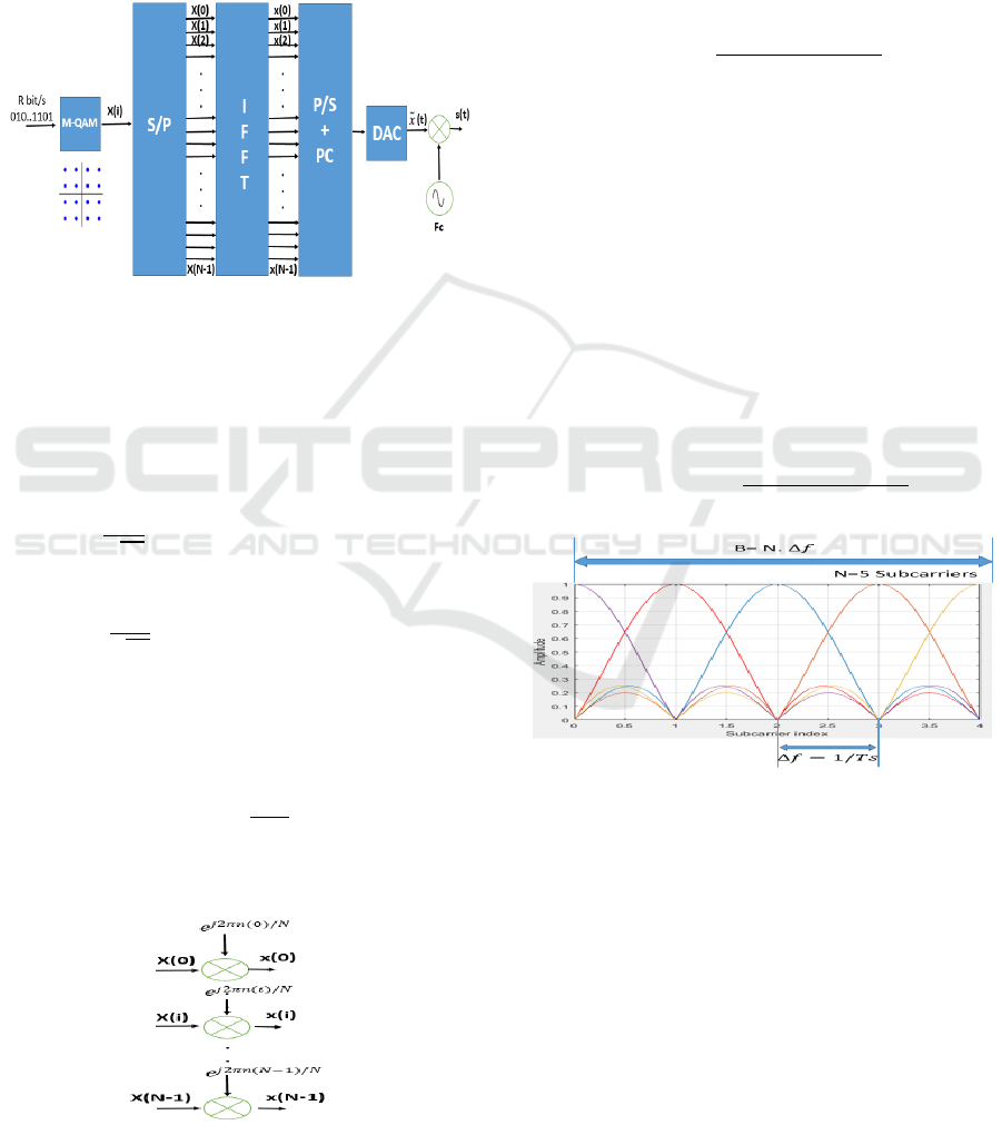
In OFDM, the data is divided into blocks of size N (N
symbols). Each block is called an "OFDM symbol»,
Figure 2.
Figure 2: OFDM Modulator transmission.
Let’s take x(n) ; n = (0, 1, 2, 3,. . . , N -1) a sequence
of complex samples in discrete time, we define the
discrete Fourier transform function DFT, Inverse
Fourier transform as the following (A.
Bahai,2004)(Yong Soo Cho,2010).
DFT
x
n
X
i
1
N
. xne
/
(1)
IDFT
X
i
x
n
1
N
. Xie
/
(2)
1iN1 ; 1nN1
s(t) represents the transmitted signal, each complex
symbol X(i) is modulated by the IFFT on the
frequency f(i) as illustrated in the figure.3.
f
i
e
1iN1
Couple
f
i
;
f
j
areOrthogonalforij
(3)
Figure 3: IFFT Orthogonal Frequency Multiplication.
2.2 OFDM Frequency Waveform
By using the OFDM, the available frequency band is
divided into several orthogonal sub channels,
carrying independent symbols. (Yong Soo Cho, 2010;
Tzi-Dar Chiueh, 2012).In time domain we note:
s
t
e
∆
i
f
TgtTs
0i
f
TgtandtT
s
(4)
In frequency domain we note:
S
f
T.
Sinπ.T.
f
n∆
f
π.T.
f
n∆
f
(5)
TTsTg ; ∆
f
1/Ts
(6)
Where:
Ts: Useful OFDM symbol duration or symbol time.
Tg: Guard interval duration.
T: Total OFDM Symbol duration.
: The n th Subcarrier.
∆: Frequency spacing between sub carriers.
The base band signals is written in time domain
respectively in frequency domain as the following:
xt X
.
g
t
(7)
X
f
T. X
.
Sinπ.T.
f
n∆
f
π.T.
f
n∆
f
(8)
Figure 4: Realization of N subcarriers orthogonality N=5.
The figure.4 represents a Matlab simulation of 5
subcarriers with a fix frequency spacing between
subcarriers ∆.The OFDM symbol in the figure 5
corresponds to a composite signal of N=5 symbols in
a parallel form, which has a duration of Ts.
In the following section (Section III) we will
propose you a new street lighting system based on the
OFDM Operations and OFDM signal spectrum as
introduced and explained in this section (Section II).
SMARTGREENS 2017 - 6th International Conference on Smart Cities and Green ICT Systems
288
3 PROPOSED STREET
LIGHTING SYSTEM BASED
ON OFDM OPERATIONS
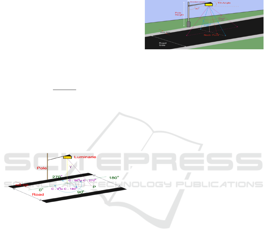
3.1 Street Lighting Norms and Design
We measure the intensity distribution of the road light
by using the C- photometric convention. Indeed, in
the C- photometry, C represents the angle on the
road surface plane, represents the angle between
vertical axis of the street lamp and lumen throwing
direction. Intensity I is calculated from the equation
of the Illuminance as the following: (Owen Ransen,
2014; Electrical4u, 2017)
Ep
I.cos
γ
h
(9)
EP: The Illuminance at point P on the road.
h: The vertical height from the point P to the
luminaire.
After calculation of the intensity, we put all the
intensity values making a C-ɣ table as per their
angular position. In this table C' is the position of
maximum intensity on the table.
Figure 5: Three basic planes of intensity considered on the
road surface with one Street lamp.
Three basic planes of intensity are considered on the
road surface with one Street lamp as shown in Figure
5: (Owen Ransen, 2014; Electrical4u, 2017)
- Plane1: C-0
to C-180
along the road.
- Plane2: C-90
to C-270
across the road.
- Plane3: Principle Plane, through the point of
maximum intensity of the light, i.e. C' to C' +
180
C' is obtained by preparing intensity distribution chart
of the street lamp on the road. Where intensity will
meet at maximum value this is the degree value of C'.
Two indices are related to the road light luminaire, the
first one is the Spread angle, representing the angle of
the luminaire to direct the luminous flux across the
road, and the second is the Throw angle, representing
the angle of the luminaire to direct the luminous flux
along the road, the figure 6 illustrates these two angle:
(Owen Ransen, 2014; Electrical4u, 2017).
γ
60
Shortthrowangle
γ
70
Longthrowangle
60
γ
70
Intermediatethrowangle
(10)
Figure 6: Spread and Throw angles representation.
3.2 Proposed Street Lighting System
based on OFDM Operations
Smart lighting means providing only the necessary
and sufficient light to see and be seen and to ensure
the safety of people and road users in general
according to their activity and the specificities of the
places, indeed when the lighting equipment is still in
good functional condition, and for a low investment,
it’s possible to realize considerable energy savings
without necessarily replacing the street lamps by
installing motion sensors and using intelligent
strategies of lighting command and lighting voltage
control as we will explain in the following chapters of
this section. Inspired from the OFDM Techniques
introduced previously in the chapter II, we propose
you in the following chapters of this paper, a new
model of street lighting system based on OFDM
operations, this model will allow us to select the
desired street lamp and to launch a proposed
waveform of lighting in function of the sensors
concerned by the detections. This proposed model
will allow us to illuminate streets intelligently by
using a new strategy of voltage command of lighting
and to reduce considerably the power consumption
during the lighting. Let’s consider now a series of N
sensors s(i) , practically, sensors are fixed to their
respective street lamps, the sensors will allow us to
inform if there is detections or not (detections of
pedestrians, vehicles, bikes …), s(i) is defined
as the
following :
s(i) = [s(1) s(2) s(3) … s(N-1) s(N)]
(11)
s
i
1 ifdetection
s
i
0 else
1
(12)
Now, we consider S a binary stream sequence of
detections of size N and
,
its associated square
matrix of size N defined as the following:
S = s(i) = [s(1) s(2) s(3) … s(N-1) s(N) ]
(13)
Proposed Model of Street Lighting System based on OFDM Operations for Smart Lighting
289
A
,
=
s1 ⋯ 0
⋮⋱⋮
0⋯sN
(14)
1i;jN
A
,
s
i
Forij
A
,
0 else
(15)
The A matrix will help us modeling the serial to
parallel converter and to plot easily overlapping
subcarrier spectrum. Now, we operates an Invert Fast
Fourier Transform IFFT along each column of the
matrix A, each column represents a subcarrier, the
IFFT is defined as the following:
D
,
= IFFT [A
,
(16)
D
,
1
N
. C
,
.
e
/
(17)
C
C
,
C
,
……C
,
……C
,
(18)
D
D
,
D
,
……D
,
……D
,
1iN
: Represents the m th column of the matrix D.
: Represents the k th column of the matrix A.
N: Represents the number of street lamps in the street
branch or road and also the subcarriers generated.
We propose to do a Fast Fourier Transformation FFT
with a resolution multiplied by N, so we’ll have the
following:
F
,
= FFT [D
,
(19)
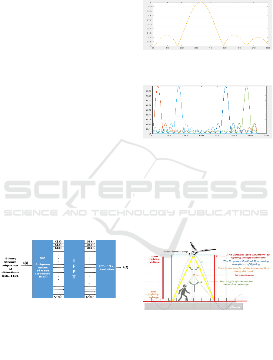
The figure 7 illustrates our proposed model of street
lighting system based on OFDM operations.
Figure 7: The proposed model of street lighting system.
The following figures illustrate the subcarriers
spectrum in frequency domain generated in different
binary sequences of detections S, we’ll take into
account the following:
- Simulation in figure 8: S1 = [0 0 1 0 0]
- Simulation in figure 9: S2 = [0 1 0 0 0 1 0 0 0 0 0
0 0 0 1 0 0 0 1 0]
Figure 8: Lighting waveform represented by subcarriers
spectrum generated for the binary sequence of detections in
a street branch of N street lamps (N=5; FFT of 16xN
resolution).
Figure 9: Lighting waveform represented by subcarriers
spectrum generated for the binary sequence of detections in
a street branch of N street lamps (N=20; FFT of 16xN
resolution).
Indeed, and according to the results obtained in the
figures (Figures 8,9) in each detection detected by a
motion sensor s(i), a Cardinal Sine Signal is launched
in the i th street lamp concerned by the detection. The
model is based on tracing the signal generated in
frequency domain as illustrated in figures 8,9, to the
time and spatial domain in order to generate the
waveform of voltage command of lighting as
illustrated in the figure 10.
Figure 10: Waveforms of lighting represented in spatial
domain in the i th Street Lamp when the i th motion sensor
is detected.
Indeed, by using the classical gate waveform of
voltage command we obtain a uniform spatial lighting
intensity as illustrated in the figure 11, by using our
proposed lighting model, cardinal sine waveform of
lighting we will obtain a degraded lighting with an
increasing intensity in the direction of the street lamp
SMARTGREENS 2017 - 6th International Conference on Smart Cities and Green ICT Systems
290
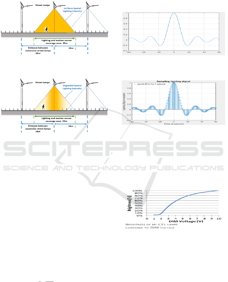
position figure 12.
Figure 11: Uniform Spatial lighting intensity by using
classical gate waveform of voltage command of lighting.
Figure 12: Degraded Spatial lighting intensity by using
proposed cardinal sine waveform of lighting.
We can notice from the figures, figure 11, 12 that
unlike the classic model "gate waveform of voltage
control of lighting", the proposed model "Cardinal
sine waveform of lighting" does not keep the lighting
voltage to the maximum, which will allow us to
optimize energy consumed at each detection during
the lighting. For voltage command, we propose to
sample the cardinal sine analog lighting waveform,
sampling can be modelled by a pulse train as the
following:
δ
tkTs
(20)
Taking into account the following:
-The power of lighting is fixed in the interval
P = [10%; 100%].
-The average speed of pedestrians is about = 1m/s.
-The distance between two successive street lamps is
d=20m.
The Cardinal Sine analog lighting waveform will
evolve in a interval of time defined as below:
τ
=
/
= 20s
(21)
The sampling of the proposed lighting waveform is
expressed as below:
Ws
t
Sinc
0.25t
.tkTs
(22)
Figure 13: Time domain representation of Cardinal Sine
analog lighting waveform evolving in a interval
time20.
Figure 14: Time domain representation of Cardinal Sine
waveform of lighting discretized evolving in an interval of
time 20.
To insure the diming of lighting, we connect dimmers
to a street lamps in order to command lighting by
varying the voltage command, the correspondence
between intensity of lighting and the voltage
command is represented in the figure
15.(Smarthomatic,2016).
Figure 15: Curve of the correspondence between intensity
of lighting and the voltage command of the dimmer.
As we notice from the figure 15, the curve represents
an aspect of logarithmic function, so we can write the
following:
IlnV
(23)
Where I representing the brightness or the intensity of
lighting, and V the voltage applied by the dimmer, so
we can write the following:
Ve
e
.
(24)
Proposed Model of Street Lighting System based on OFDM Operations for Smart Lighting
291

Figure 16: Time domain representation of the proposed
waveform of lighting and the proposed waveform of
voltage command.
Figure 17: Time domain representation of the proposed
voltage command of lighting (discretized) the dimmer
should apply to illuminate with the proposed lighting
model.
3.3 Energy Saving
We propose in this chapter to make an analysis and
comparison between the classical gate waveform of
voltage command and our proposed cardinal sine
waveform of voltage command .The aim, is to
determine which of these models save the most
energy during the lighting. With a temporization
lighting time of
τ = 20s and a power of lighting of
(P=13 W, 1500 Lumens) evolving between 100% and
10% in standby mode. We can calculate the energy
consumption:
E
P.
dx
(25)
=P.τ 13
W
.90%.20s
=234Joules
E
P.Sinc0.25x
dx
(26)
≃13
W
.11,6≃150,8Joules
Where
is the energy consumption of the classical
model and
the energy consumption of our
proposed model, and
∏
the gate function defined
as the following:
t
1;
2
t
2
0,1;t
2
andt
2
(27)
Table 1: Table summarizing the energy consumption
analysis between the classical lighting model and the
proposed lighting model.
RATE OF POWER
ENERGY
CONSUMPTION
CLASSICAL LIGHTING
MODEL
100%
PROPOSED CARDINAL
SINE LIGHTING MODEL
64.5%
We notice that the proposed cardinal sine model of
voltage command save energy during the lighting
comparing to the classical model with a optimization
gain of 35,5 %.
4 CONCLUSION
We proposed in this paper a model of street lighting
systems based on OFDM operations, this technique is
useful to switch On/Off the street lamp and to launch
a proposed waveform of voltage command of lighting
when pedestrian or vehicle detections are occurred
along the roads. This proposed model will allow us to
illuminate roads intelligently by using a new strategy
of voltage command of lighting and to reduce
considerably the power consumption during the
lighting, and so illuminating smartly. A complete
study of this proposed strategy and saving energy,
will be the subject of our future works and
publications.
REFERENCES
A. Bahai, B. R. Saltzberg, and M. Ergen, 2004. The book,
Multi-Carrier Digital Communications: Theory and
Applications of OFDM, 2nd ed., New York: Springer
Verlag, 2004.
Yong Soo Cho, Jaekwon Kim, Won Young Yang, Chung
G. Kang, 2010.The book, Mimo-OFDM Wireless
Communications with Matlab, IEEE 2010.
Owen Ransen, 2014.The book, Candelas, Lumens and Lux.
Electrical4u, 2017. Road lighting design Website, ONLINE
ELECTRICAL ENGINEERING STUDY SITE, http://
www.electrical4u.com/road-lighting-design/.
Tzi-Dar Chiueh, Pei-Yun Tsai, I-Wei Lai, 2012. The Book,
Baseband Receiver Design for Wireless MIMO-OFDM
Communications 2
nd
Edition.
Smarthomatic, a secure and extendable Open Source home
automation systemcopyright2013.. 2016, https://www.
smarthomatic.org/devices/dimmer.html.
SMARTGREENS 2017 - 6th International Conference on Smart Cities and Green ICT Systems
292
