
Global Energy Management for Propulsion, Thermal Management
System of a Series-parallel Hybrid Electric Vehicle
Xiaoxia Sun, Chunming Shao, Guozhu Wang, Rongpeng Li, Danhua Niu and Jun Shi
China North Vehicle Research Institute, Beijing, China
Keywords: Global Energy Management, Dynamic Heat Characteristics, Adaptive Controllable Thermal Management,
Coupled Modelling.
Abstract: Energy management in vehicles is a key issue, especially in the case of hybrid electric vehicle. In this paper,
a global energy management for propulsion, thermal management system of a series-parallel hybrid electric
vehicle is studied. An adaptive controllable thermal management system with two different control
strategies suitable for series-parallel hybrid electric vehicle is presented. According to the vehicle structure
and schematic, a multi-disciplined coupled model of a series-parallel hybrid electric vehicle combined with
propulsion system model and thermal management system model is proposed. The coupled model is
explored with the hybrid modelling method which combines experiment modelling and theory modelling.
Then the vehicle driving cycle simulations under different cooling control strategies are conducted. Results
show that the coupled simulation model can be used to study the energy delivery, distribution and dynamic
heat characteristics of propulsion system efficiently. Compared to the traditional on-off cooling control
strategy, the power consumption of thermal management system using rule-based cooling control strategy
can be decreased by 31.7%.
1 INTRODUCTION
Nowadays, concerns about air pollution and future
of energy issues are dramatically increased. In the
short term full electric vehicles are prepared to be a
substitute to the traditional internal combustion
vehicles because of the technology challenges of
energy storage system. At present, the hybrid
electric vehicle (HEV) is the viable alternative to
conventional vehicle. Series-parallel hybrid electric
vehicle (SPHEV) is a complex type of HEV, which
combines the series and parallel structure with a
planetary power split device. With advanced control
strategy it can not only take advantage of both series
and parallel HEV but also avoid their disadvantages
(C. C. Chan, 2002).
With the potential for achieving higher fuel
economy, PSHEV has been seen as one of the
hybrid powertrain architecture to improve fuel
economy when their power-management algorithms
are properly designed. Most of the attention has been
given to designing energy management control
systems in PSHEVs which is responsible to achieve
better vehicle fuel efficiency (C. L. Xiang, 2017).
Aside of propulsion, thermal management
occupies a significant part of the total energy
consumption of the hybrid electric vehicle. Recently,
there are a series of research on the thermal
management and power distribution of HEV which
is presented in depth. Among these, there are some
researches considering the effect of thermal
management based on different system structures (S.
Park, 2008,2010) and different control strategies (F.
J. Espadafor, 2015) on whole energy management of
series hybrid electric vehicle. The existing energy
management strategies of SPHEVs just focus on the
improvement of fuel efficiency based on hot engine
characteristics neglecting the effect of thermal
management system such as temperature on the
propulsion system components performance and the
vehicle power demand.
In this paper, an adaptive controllable thermal
management system suitable for SPHEV is
presented. According to the vehicle structure and
schematic, a mechanical-electrical-thermal coupled
model of a SPHEV combined with propulsion
system model and thermal management system
332
Sun, X., Shao, C., Wang, G., Li, R., Niu, D. and Shi, J.
Global Energy Management for Propulsion, Thermal Management System of A Series-parallel Hybrid Electric Vehicle .
DOI: 10.5220/0006370403320338
In Proceedings of the 3rd International Conference on Vehicle Technology and Intelligent Transport Systems (VEHITS 2017), pages 332-338
ISBN: 978-989-758-242-4
Copyright © 2017 by SCITEPRESS – Science and Technology Publications, Lda. All rights reserved
model is proposed to study the global energy
management of the whole vehicle.
2 SCHEMATIC OF SERIES-
PARALLEL HYBRID
ELECTRIC VEHICLE
2.1 Schematic of Propulsion System
Compared to the others HEV propulsion system, the
SPHEV is characterized by multi-range
electromechanical transmission belongs to the power
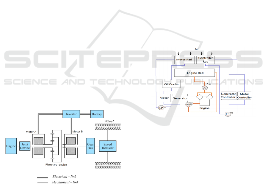
split hybrid propulsion system. The schematic of the
SPHEV propulsion system is illustrated in Figure 1.
Except for internal combustion engine, there are
also two motors in the hybrid propulsion system.
These main components are connected by the
planetary device. The internal combustion engine is
jointed to the planet carrier of the planetary device.
The motor A is jointed to the sun gear of the
planetary device. The motor B is jointed to the ring
of the planetary device which is paralleled with the
vehicle output shaft. Considering to the vehicle
driving conditions, both the motor A and the motor
B can not only operate as a generator but also work
as a driving motor. In SPHEV, the engine speed is
adjusted by the motor A when it works as a
generator according to the work conditions. The
power generated by the engine is split by the
planetary power coupling device and then formed
into different power flow under different driving
condition.
Figure 1: Schematic of series-parallel hybrid electric
vehicle propulsion system with planetary device.
2.2 Schematic of Thermal Management
System
An adaptive controllable thermal management
system suitable for SPHEV is proposed which is
shown in Figure 2. It is fully designed on the
consideration of the global energy management
which not only consider the temperature effect on
the propulsion system components but also take into
account the effect of thermal management power
consuming on the whole vehicle power demand.
There are three water circulation loops in the
thermal management system. One is high
temperature water circulation loop which is used to
cool the internal combustion engine. The other two
are low temperature water circulation loops which
are used to cool the electric motors and their
controllers separately. The oil cooler is arranged in
the motor low temperature water circulation loop
because of transmission oi temperature requirement.
Three radiators are integrated into one radiator
module. In the air loop, an air stream is inducted
through a grille from the top of vehicle which is
powered by two electric fans. Then it passes in turn
through two low temperature water radiator which is
installed in parallel and one high temperature water
radiator which is installed with the low temperature
radiators in series. Finally, the air stream washes
over the powertrain set in the power compartment
and be exhausted by the fans through another grille.
Figure 2: Schematic of series-parallel hybrid electric
vehicle thermal management system (Rad: Radiator, EP:
Electric Pump, MP: Mechanical Pump, T/S: Thermostat).
3 MULTI-DISCIPLINED
COUPLED SIMULATION
MODELLING
A mechanical-electrical-thermal coupled model is
established by multi-disciplinary hybrid modelling
method which can decompose the whole system into
several relatively independent subsystems. The large
coupling problem can be decomposed into small and
easy handling sub-problems. The complex mutual
coupled Modelling can be converted into a number
of independent subsystem modelling.
Global Energy Management for Propulsion, Thermal Management System of A Series-parallel Hybrid Electric Vehicle
333
3.1 Propulsion System Modelling
This part introduces the models of the components
in the vehicle propulsion system. The hybrid
modelling method which combines experiment
modelling with theory modelling is adopted.
3.1.1 Internal Combustion Engine
Due to the significant nonlinearity of the engine, the
real engine model is quite complicated. In this paper,
the experimental data are used to obtain the engine
performance maps, including the engine's external
characteristic map and the engine fuel consumption
characteristics map. Then an engine torque output
module is used to acquire the engine output torque
from a look-up table by the engine throttle signal
and the current speed. The engine fuel consumption
is calculated by the current engine speed, torque and
engine fuel consumption rate.
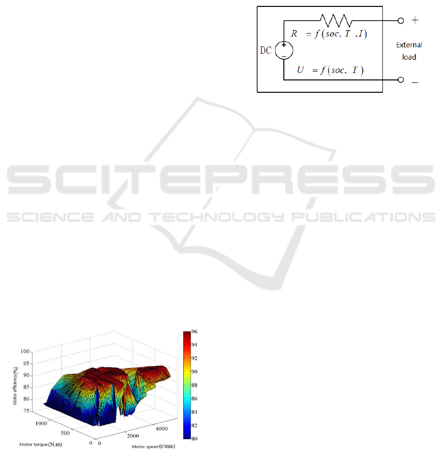
3.1.2 Motor and Controller System
The experimental modelling method is also used in
motors and controllers modelling process, which
emphasizes on the input and output characteristics.
The characteristic maps of the motors are obtained
by the motor bench test. The motor model mainly
includes a torque calculation module and a current
calculation module. Firstly, the motor receives the
target torque command. Then the torque calculation
module determines the maximum drive torque in
electric operating condition or the maximum braking
torque in braking condition which can be used as a
constraint of the motor output torque. Motor current
calculation module is used to calculate the driving
power or the generating power by the motor current
output speed, torque and motor efficiency factor
acquired from the motor efficiency curve shown in
Figure 3.
Figure 3: Motor efficiency curve.
3.1.3 Energy Storage System
In the SPHEV, the energy storage system is lithium
battery pack. In this paper, the model of the battery
pack is modelled by the internal resistance model.
The battery pack is modelled as a controllable
voltage source and a variable resistor. The
equivalent circuit diagram is shown in Figure 4. The
battery model outputs the state of charge (SOC) of
the battery pack and provides an electrical interface
to the generator and the motor.
Figure 4: Battery internal resistor model. (R: Battery
internal resistor, U: Voltage, soc: state of charge, T:
Temperature, I: Current ).
3.2 Thermal Management System
Modelling
In order to guarantee working performance and
reliability of the propulsion system components, an
adaptive controllable thermal management system
has been used for the propulsion system heat
dissipation. On the other side, the thermal
management system requires electrical energy to
fulfil its duty. Therefore the power consumption of
the thermal management system drive components
such as electric fan and electric pump need to be
considered in the total power demand.
The battery has the integrated cooling system in
the battery pack which is not the research focus in
this paper. So this part can be neglect in the thermal
management system.
3.2.1 Heat Sink Component
Heat sink components are heat exchangers that reject
heat to the ambient air. The calculation applies the
following formula (Z. P. Yao, 2001).
)(
'''
aapaaa
ttcm
(1)
a
is the quantity of heat removed of air side,
a
m
is the air mass flow,
pa
c
is the specific heat capacity of
the air,
'
a
t
is the inlet temperature of air,
''
a
t
is the
outlet temperature of air.
VEHITS 2017 - 3rd International Conference on Vehicle Technology and Intelligent Transport Systems
334
)(
"'
wwpwww
ttcm
(2)
w
is the quantity of heat removed of water side,
w
m is the mass flow rate of water,
wp
c
is the specific
heat capacity of water,
'
w
t
is the inlet temperature of
water,
''
w
t
is the outlet temperature of water.
''''
''
''''''
ln
wa
wa
wawa
m
ms
tt
tt
tttt
t
tKA
(3)
s
is the quantity of heat removed of radiator,
K
is the heat transfer coefficient of the radiator,
A
is the heat transfer area,
m
t
is the difference in
temperature between the fluid entering the heat
exchanger.
e
aa
d
L
u
fP
2
2
(4)
P
is the air flow pressure drop,
f
is the air
flow resistance coefficient,
a
is the air density,
a
u
is the air velocity, L is the length of flow pipe,
e
d is
the equivalent diameter.
g
u
d
l
h
c
f
2
Re
316.0
2
25.0
(5)
f
h
is the coolant pressure loss of the straight
pipe,
Re
is the Renault number,
l
is the length of
the coolant flow pipe,
d is the inside diameter of
the pipe,
c
u is the coolant velocity,
g
is the
acceleration of gravity.
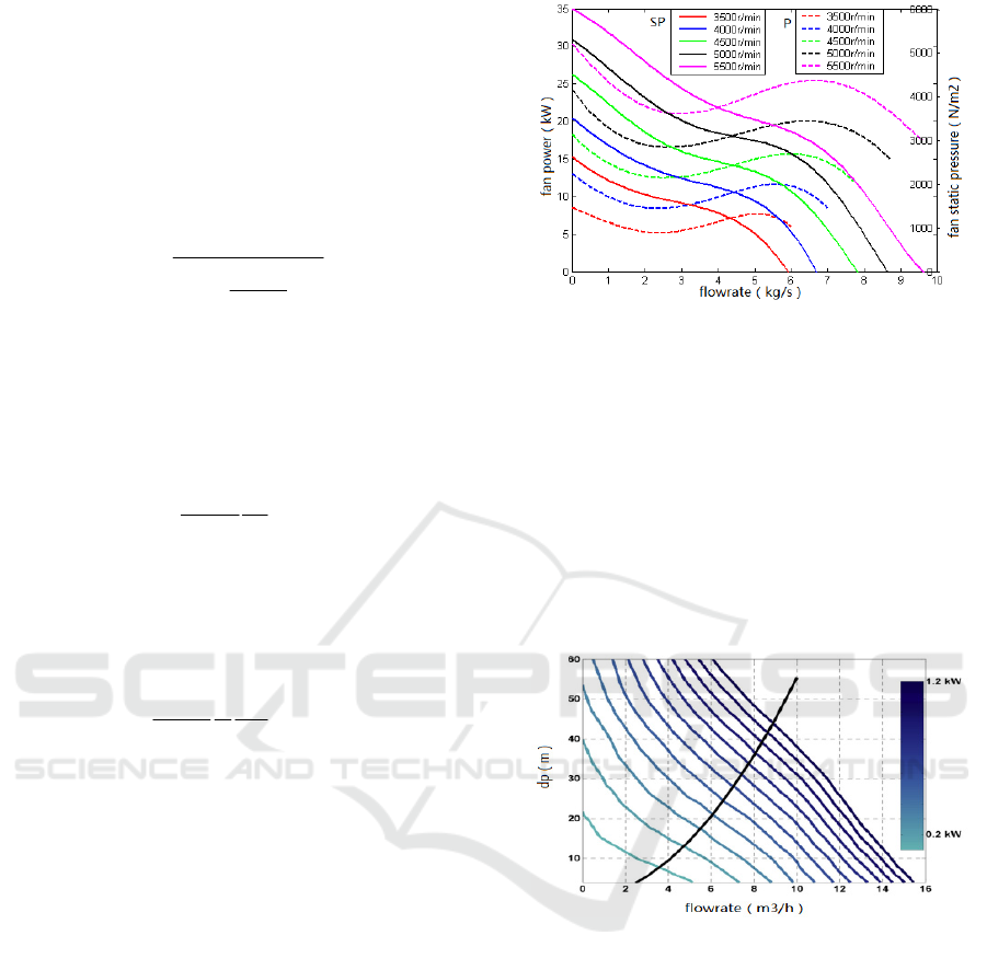
3.2.2 Electric Fan
The heat dissipation of the internal combustion
engine and electrical components is delivered by
water and through radiators where it is transferred to
air by electric fans. Two electrical fans have been
arranged in parallel according to the structure of the
thermal management system. The specific
performance curve of the electric fan is described in
Figure 5.
Figure 5: Electric fan performance curve. (SP: static
pressure, P: power).
3.2.3 Coolant Pump
There are totally three pumps in the thermal
management system. Two electric water pumps are
used in the circulation of the motor cooling circuit
and controller cooling circuit. One mechanic water
pump which is propelled by engine directly is used
in the engine cooling circuit. The specific
performance curve of the electric pump is described
in Figure 6(Francisco, 2015).
Figure 6: Electric pump performance curve.
4 GLOBAL ENERGY
MANAGEMENT STRATEGY
FOR SPHEV
The power distribution flexibility of SPHEV brings
a more complex energy management problem. The
energy management strategy of HEV can be divided
into two categories, namely rule-based and
optimization-based. Although on some particular
occasions driving cycle can be known, it is usually
unavailable in some off-road conditions which
causes rule-based strategies be the most useful. In
Global Energy Management for Propulsion, Thermal Management System of A Series-parallel Hybrid Electric Vehicle
335
this paper a rule-based energy management strategy
has been chosen for the SPHEV.
According to the driving condition, the SPHEV
can explore a variety of working modes. Vehicle
stop mode includes vehicle stopping and stopping &
charging conditions. The latter one is a special case
of the vehicle stopping mode. Electric driving mode
is applied in the low speed and small load condition.
Engine single driving mode is applied in the
situation that vehicle required torque is in the engine
high efficiency load areas. Hybrid driving mode is
applied to full load acceleration or climbing
conditions. Braking mode includes electrical braking
and mechanical braking is applied in brake
condition.
For different working modes, the energy
management adopts the control strategy based on the
power distribution rules. First, the total demand
power of the vehicle including the vehicle driving
power and auxiliary power is distributed between the
engine and the battery, and then the engine power is
distributed between the motor A and the mechanical
power. On the premise that battery SOC is
maintained at optimal working range, engine works
in the optimal efficiency range by the adjustment of
the battery. Motor A is used to adjust the engine
speed into the optimal speed range in order to realize
the best fuel consumption.
Under this situation, the speeds of fans and
pumps are controlled by the thermal management
system which is also considered in the global energy
management system. There are two thermal
management control strategies are applied in this
paper. One is traditional on-off control strategy. The
other one is rule-based control strategy which is
realized by the rule-based map determined by the
different vehicle working modes. Compared to the
traditional on-off control, this rule-based cooling
control strategy is more elaborate. The specific
control target temperatures of propulsion
components can be seen in Table 1.
Table 1: The control target temperatures of propulsion
components.
Propulsion component
Control target outlet water
temperature(K)
Engine 376
Generator 358
Motor 358
Generator controller 338
Motor controller 338
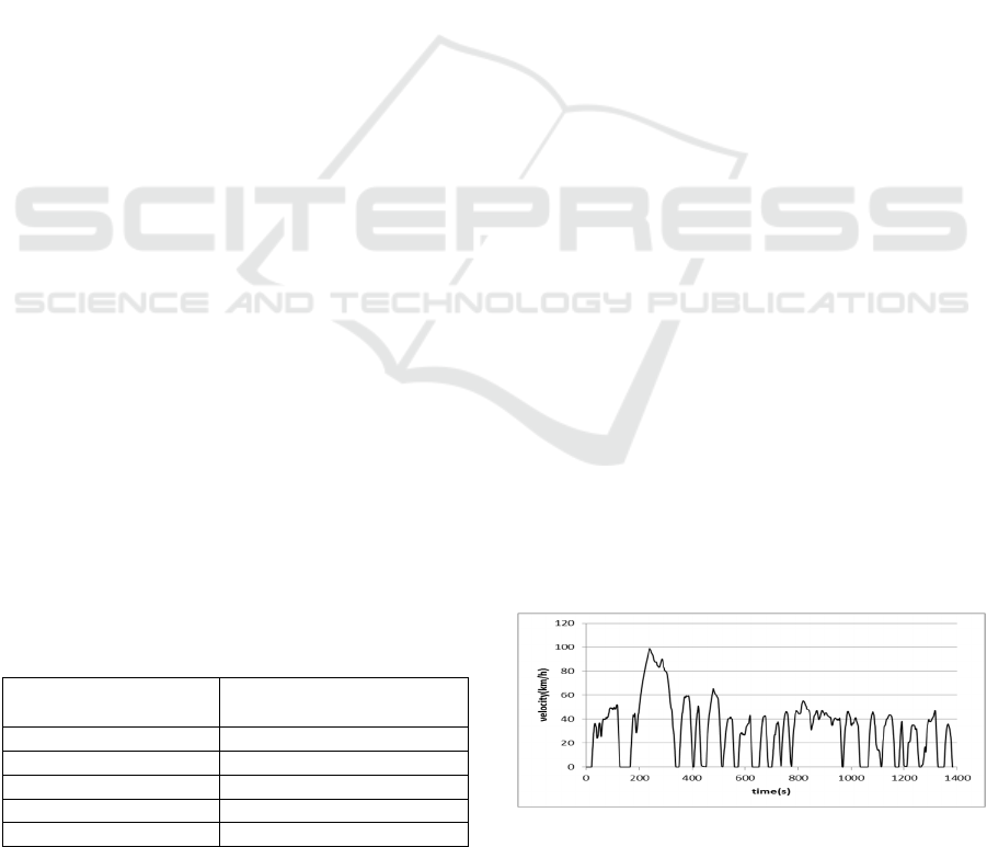
5 RESULTS AND DISCUSSIONS
A series of simulations under UDDS driving cycle
using different cooling control strategies are
conducted. The international general urban road
driving cycle UDDS is shown in Figure 7. In the
UDDS driving cycle, the maximum velocity is 91.2
km/h. In the simulation, the initial SOC of the
battery is set to 0.8. The vehicle needs to start, stop,
accelerate and brake frequently throughout this
driving cycle. The total demanding power of
SPHEV is shown in Figure 8. The demanding power
is distributed between the engine power and the
battery power. The engine power over the whole
driving cycle can be seen in Figure 9. The histories
of battery SOC and power over the driving cycle can
be seen in Figure 10. During the driving cycle, the
SOC of the battery always declines. In light of
recycling energy of the electrical brake, the SOC
changing curve goes up and down accordingly
which is related to the charge-and-recharge process.
Figure 11 shows the engine and electric components
temperature histories over the driving cycle under
rule-based cooling control strategy. Figure 12 shows
the vehicle thermal management system power
consumption over the driving cycle under different
cooling control strategies.
The simulation results show that the adaptive
controllable thermal management system with rule-
based control strategy proposed in this research is
suitable for the SPHEV, which can satisfy the heat
dissipation requirements of the propulsion
components under different driving conditions.
Under this circumstance, the propulsion components
can work effectively in a better temperature range.
On the other side, the power consumption of the
vehicle thermal management system can be reduced
significantly by using the rule-based control strategy.
Compared to the traditional on-off control strategy,
the power consumption of the thermal management
system using rule-based control strategy can be
decreased by 31.7%.
Figure 7: UDDS driving cycle.
VEHITS 2017 - 3rd International Conference on Vehicle Technology and Intelligent Transport Systems
336
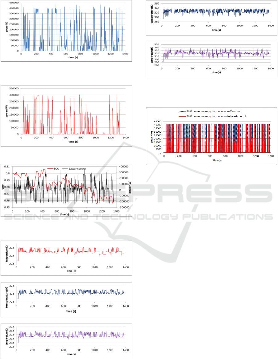
Figure 8: vehicle total demanding power under UDDS
driving cycle.
Figure 9: Engine Power under UDDS driving cycle.
Figure 10: Battery state of charge and power under UDDS
driving cycle.
(a) Engine
(b) Motor
(c) Generator
(d) Motor controller
(e) Generator controller
Figure 11: Temperature histories of engine and electric
components.
Figure 12: Power consumption of thermal management
system under different control strategies. (TMS: thermal
management system).
6 CONCLUSIONS
The mechanical-electrical-thermal coupled model
established in this paper is very efficient in the
power delivery, distribution and dynamic heat
response research of SPHEV. With the multi-
disciplined coupled model, a global energy
management can be realized. The propulsion
components heat characteristic and thermal
management system power consumption can be
synthetically considered. With suitable cooling
control strategy, it can not only enhance the
propulsion performance, but also reduce the system
power consumption.
ACKNOWLEDGEMENTS
Fanatical and technical supports from the Chinese
Scholarship fund and China North Vehicle Research
Institute are gratefully acknowledged.
Global Energy Management for Propulsion, Thermal Management System of A Series-parallel Hybrid Electric Vehicle
337

REFERENCES
C. C. Chan, 2002. The state of the art of electric and
hybrid vehicle, in Proceedings of IEEE, Vol. 90, No. 2,
pp. 247-275.
C. L. Xiang, F. Ding, W. D. Wang and W. He, 2017.
Energy management of a dual-mode power-split
hybrid electric vehicle based on velocity prediction
and nonlinear model predictive control, Appl Energy,
189: 640-653.
S. J. Park and D. Jung, 2008. Numerical Modeling and
Simulation of the Vehicle Cooling System for a Heavy
Duty Series Hybrid Electric Vehicle, SAE Paper No.
2008-01-2421.
S. J. Park and D. Jung, 2010. Design of Vehicle Cooling
System Architecture for a Heavy Duty Series-Hybrid
Electric Vehicle Using Numerical System Simulations,
Journal of Engineering for Gas Turbines and Power,
Vol. 132, 2010, pp. 092802-092802-11.
F. J. Espadafor, D. P. Guerrero, E. C. Trujillo, M. T.
Garcia and J. Wideberg, 2015. Fully optimizied energy
management for propulsion, thermal cooling and
auxiliaries of a series hybrid electric vehicle, Appl.
Thermal Engineering 91 (2015) 694-705.
Z. P. Yao and X. G.Wang, 2001. Heat transfer in vehicle
cooling, Beijing: Beijing Institute of Technology
Press, 2001, pp.129-147.
VEHITS 2017 - 3rd International Conference on Vehicle Technology and Intelligent Transport Systems
338
