A Lightweight Integrity Protection Scheme for Fast Communications in
Smart Grid
Alireza Jolfaei and Krishna Kant
Department of Computer Science, Temple University, Philadelphia, U.S.A.
Keywords:
GOOSE Message, Integrity Protection, Permutation, Phasor Measurement, Substation Automation System.
Abstract:
Due to the mission-critical nature of energy management, smart power grids are prime targets for cyber-attacks.
A key security objective in the smart grid is to protect the integrity of synchronized real-time measurements
taken by phasor measurement units (PMUs). The current communication protocol in substation automation
allows the transmission of PMU data in absence of integrity protection for applications that strictly require
low communication latency. This leaves the PMU data vulnerable to man-in-the-middle attacks. In this paper,
a lightweight and secure integrity protection algorithm has been proposed to maintain the integrity of PMU
data, which fills the missing integrity protection in the IEC 61850-90-5 standard, when the MAC identifier
is declared 0. The rigorous security analysis proves the security of the proposed integrity protection method
against ciphertext-only attacks and known/chosen plaintext attacks. A comparison with existing integrity
protection methods shows that our method is much faster, and is also the only integrity protection scheme
that meets the strict timing requirement. Not only the proposed method can be used in power protection
applications, but it also can be used in emerging anomaly detection scenarios, where a fast integrity check
coupled with low latency communications is used for multiple rounds of message exchanges.
1 INTRODUCTION
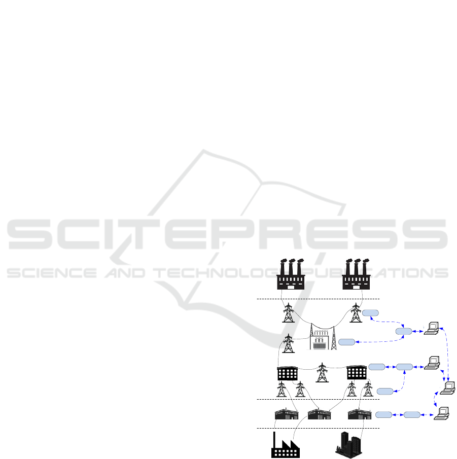
The supervisory control and data acquisition
(SCADA) systems in emerging smart grids monitor,
control and protect power system components by
making use of a network of phasor measurement units
(PMUs) and phasor data concentrators (PDC). As
shown in Figure 1, synchronous PMUs and PDCs are
installed in various locations (key substations) of the
transmission and distribution lines. PMUs measure
voltage magnitude, phase, and line frequency 30 to
60 times a second; and send these measurements
along with the global position system (GPS) loca-
tion of the PMU to PDCs. This is done through
a publish-subscribe mechanism, where the PMUs
work as publishers to which the PDCs subscribe.
A PDC receives data from many (typically 3 to 32)
PMUs, and then sorts and aggregates the received
data based on the time-tag. The aggregated data is
then relayed using a two-way communication system
to a number of local control centers (LCCs), which
coordinate their actions interacting with a federated
control center (FCC). Subsequently, LCCs draw
the best overall snapshot solution using all PMU
measurements (Weng et al., 2016).
Transmission
Distribution
Generation
Costumers
Transmission Substation
Subtransmission
Distribution
Substations
Transmission
Distribution
Generation
Costumers
Transmission Substation
Subtransmission
Distribution Substations
PMU
PMU
PDC
PMU
PMU
PDC
PMU PDC
LCC
FCC
LCC
LCC
Figure 1: Typical model of a power grid architecture.
Control centers use the IEC 61850-90-5 standard
to communicate with smart measurement units (IEC
61850-90-5, 2012). This standard utilizes a generic
object oriented substation event (GOOSE) proto-
col for fast relay-to-relay communications. Since
GOOSE messages are time critical, they are only as-
Jolfaei, A. and Kant, K.
A Lightweight Integrity Protection Scheme for Fast Communications in Smart Grid.
DOI: 10.5220/0006394200310042
In Proceedings of the 14th International Joint Conference on e-Business and Telecommunications (ICETE 2017) - Volume 4: SECRYPT, pages 31-42
ISBN: 978-989-758-259-2
Copyright © 2017 by SCITEPRESS – Science and Technology Publications, Lda. All rights reserved
31

Table 1: Size of payload data under various PMU/PDC con-
figurations
Number
of PMU
voltage
PMU
data
size
PDC data size Applicability
channels (bytes) 3 PMUs 6 PMUs 10 PMUs
1 40 104 200 328
Single phase
line in dis-
tribution sys-
tems
3 56 120 216 344
3-phase
power trans-
mission
lines
6 80 144 240 368
power trans-
mission lines
8 96 160 256 384
power trans-
mission lines
10 112 176 272 400
power trans-
mission lines
Table 2: Allowed values for MAC value calculation.
Identifier MAC algorithm Key size (bits)
0 None None
1 SHA-256 80
2 SHA-256 128
3 SHA-256 256
4 AES-GMAC 64
5 AES-GMAC 128
sociated with three layers of the open systems inter-
connection (OSI) model, namely, physical, data-link,
and application layers. IEC 61850 utilizes a standard-
ized Ethernet frame with a maximum payload size of
1492 bytes (Fan et al., 2015). The number of required
measurements depends on the topology of the power
grid as well as the requirements of optimal estimation
of the system states (Martin, K., Zwergel, A., and Ka-
postasy, D., 2015). Generally, in each substation, the
principal bus voltages should be included in the mea-
surement set. To this end, several PMUs are normally
used to cover a large substation. The size of mea-
surement data depends on the number of voltages that
a PMU measures. Table 1 gives the size of payload
data in transmission and distribution substations un-
der various PMU/PDC configurations.
Although the utilization of PMUs has facilitated
the efficient management and delivery of power in
current smart grids, it is vulnerable to integrity at-
tacks. The standard for formatting and delivery of
PMU data (IEEE Standard C37.118 (Martin et al.,
2008)) includes no end-to-end security mechanisms,
and transmits messages in plaintext without any
mechanism to protect their integrity. Although, a
cyclic redundancy check (CRC) (Sobolewski, 2003)
is used in the PMU data frame, the integrity protec-
tion of a CRC is null, as it cannot detect intentional
tampering. To this end, IEC 61850-90-5 mandates
the use of a number of message authentication code
(MAC) algorithms (Table 2), which are determined by
an identifier in the message header based upon latency
requirements. However, the complete deployment
of this standard will take a long time (Seyed Reza
et al., 2016) because of the compatibility issues of the
standard as well as the hardware issues. For exam-
ple, there are still many PMUs and PDCs in opera-
tion that have no cryptographic acceleration (Pappu
et al., 2013). In addition, when the latency implied
by the MAC implementation cannot be tolerated, IEC
61850-90-5 allows the transmission of messages in
the absence of integrity protection, as shown in Ta-
ble 2. This mainly happens in protection applications
where time is critical and therefore a fast message
communication is required. Examples of time criti-
cal applications are load shed (Adamiak et al., 2014)
and synchrophasor-assisted transfer trip (Kundu and
Pradhan, 2014) where a trip signal is sent from a sub-
station to another that could be more than 100 miles
away. In such applications, the use of MAC algorithm
is largely disabled by setting the identifier to zero.
This leaves the PMU data vulnerable to man-in-the-
middle attacks, which can alter the current phasor of
the bus, for instance, to a value greater than the maxi-
mum rated current of the line or even to zero amperes.
This would trigger protective relays to switch on and
off, which could be costly to electrical equipment and
perturb the grid, potentially leading to blackouts.
Delay requirements for power system networks
depend on a number of parameters, such as the spe-
cific protection equipment used. Most power line
equipment can endure faults or short circuits for up
to approximately five power cycles before experienc-
ing irreversible damage or affecting other segments
in the network. This translates to total fault clearance
time of less than 84 ms. However, as a safety pre-
caution, actual operation time of protection systems
is limited to approximately 70 percent of this period,
including fault recognition time, command transmis-
sion time and line breaker switching time (Wetterwald
P. and Raymond J., 2015). Some system components,
such as large electromechanical switches, require par-
ticularly long time to operate and take up the major-
ity of the total clearance time, leaving only a 10 ms
window for the communications part of the protection
scheme, independent of the distance to travel. Given
the sensitivity of the issue, communication networks
impose requirements that are even more stringent, for
instance IEC 61850 standard limits the transfer time
for protection messages to
1
4
cycle or 4 ms (for 60 Hz
lines) for the most critical messages.
SECRYPT 2017 - 14th International Conference on Security and Cryptography
32

To meet the 4 ms latency requirement, we are thus
compelled to look for a more lightweight and a non-
hash-based solution. A potential solution is in the
use of a fast checksum, which has the advantage of
having less computational cost. Checksums are com-
mon methods for detecting accidental data corruption,
for instance, in TCP (Zander et al., 2007) and ZLIB
(Sofia et al., 2015); and compared to MACs, they im-
pose much less computational overheads. However,
since checksums can be easily spoofed, we propose a
novel integrity protection method, which hides check-
sum bits inside payload data using a fast bit permuta-
tion technique. Our rigorous security analysis shows
no weaknesses in the proposed method, and demon-
strates no simple method of recovering the secret key.
We also confirm the security of the proposed integrity
protection method against ciphertext-only attacks and
known/chosen plaintext attacks. To the best of our
knowledge, the proposed method is the first secure
technical solution that meets the strict communication
latency requirements in protective relaying in trans-
mission and distribution substations.
The remainder of this paper is organized as fol-
lows. Section 2 summarizes the related work. Sec-
tion 3 provides details of the proposed embedding
and integrity verification algorithms. The security of
the proposed method is evaluated using an adversarial
model in Sections 4. Section 5 evaluates the perfor-
mance of the proposed method with respect to compu-
tational complexity and running time, and the results
are compared with previous works. Finally, Section
6 concludes that the proposed scheme is secure, effi-
cient and feasible.
2 RELATED WORK
Recent research has mainly been focused on preserv-
ing the integrity of PMU data in applications where
latency is on the order of seconds (rather than mil-
liseconds), such as static state estimation, power flow
analysis and model validation. The integrity prob-
lem in such applications can be addressed using con-
ventional hash based techniques, such as a cipher-
based MAC (CMAC) (Dworkin, 2007) and a hash-
based MAC (HMAC) (Khan et al., 2007). How-
ever, these solutions cannot be used in power sys-
tem protection because of the latency implied by
the overheads. Despite the importance of data in-
tegrity in the protection of power equipment, only a
few technological solutions have been given, (Guo
et al., 2007; Zhang et al., 2008; Abuadbba and Khalil,
2015; Abuadbba et al., 2016), which mainly utilized
steganographic methods. Compared to crypto primi-
tives, steganographic methods normally require less
memory, power and processing capabilities, which
can suit the constrained capabilities of smart grid in-
frastructure.
In (Guo et al., 2007), Guo et al. proposed a fragile
watermarking method for protecting the integrity of
payload data. In this scheme, payload is firstly split
into groups of variable size. The size of the group
is determined adaptively as a function of the data it-
self. A secure hash function, such as MD5, is then
applied to each data element in the payload. If the
hash value is zero, then the data element marks the
end of the group. A watermark is formed by both the
current group hash value and the group hash value of
the next group. The watermark is stored in the least
significant bits of all data elements. However, Guo et
al.’s watermarking scheme needs to compute a secure
hash function several times. Therefore, it is compu-
tationally expensive for the microprocessors used in
PMUs.
In (Zhang et al., 2008), Zhang et al. proposed
an end-to-end, statistical approach for the integrity
protection of sensory measurement data using a di-
rect spread spectrum sequence (DSSS) based water-
marking technique. In this scheme, the measurement
data, which is sent from the sender nodes, is visual-
ized as an image at different time snapshots, in which
every sender node is viewed as a pixel and its value
corresponds to the gray level of the pixel. Follow-
ing this equivalency, a watermark is embedded in this
image in a distributed fashion at each node. Given
the watermark as a prior knowledge, the receiver is
then able to verify the integrity of the measurement
data. However, the proposed method is disclosed us-
ing known/chosen plaintext attacks, because the size
of embedding data is much smaller than the size of
payload data, and watermarks are generated under the
same key.
In (Abuadbba and Khalil, 2015), Abuadbba and
Khalil proposed a steganographic method, which pro-
tects the integrity of smart grid readings by hiding a
confidential information (a fingerprint) bit-by-bit in-
side the detailed sub-band coefficients of the discrete
wavelet transform (DWT) of the payload data. Al-
though this method is much faster than MAC-based
solutions, it cannot protect the integrity of the com-
plete payload data, because the adversary can simply
spoof a fradualent message by modifying the approx-
imation coefficients of DWT of the payload data. In
other words, only one pair of covertext and stegotext
is enough to break the integrity protection algorithm.
In addition, the embedding process makes irreversible
distortions at the location of hidden bits in the cover-
text. Therefore, a portion of measurement data will be
A Lightweight Integrity Protection Scheme for Fast Communications in Smart Grid
33

lost, which may impact the decision making process
of control centers. The transmitted stegotext is highly
prone to intentional (interference) and unintentional
(noise) attacks rendering the steganography based in-
tegrity protection solutions impractical. Indeed, any
slight change in the transmitted stegotext will result
in the loss of embedded information, and more sig-
nificantly, loss of faith in the received GOOSE mes-
sage. To this end, Abuadbba et al. (Abuadbba et al.,
2016) combined a 3D DWT based steganographic
method with an error detection and correction tech-
nique, namely, BCH syndrome codes, to detect and
recover any change in the payload data. However,
the size of hidden data is much less than the size
of payload data, and therefore, similar to (Abuadbba
and Khalil, 2015), the location of the embedded data
is easily disclosed by making use of known/chosen
covertext attacks.
It follows that steganography by itself cannot suf-
ficiently address the integrity problem, and it needs to
be combined with another method, such as hashing or
encryption, to make the stegotext secure from attacks.
To this end, we propose a novel lightweight solution
for the integrity problem, which is secure from well-
known attacks.
3 PROPOSED INTEGRITY
PROTECTION SCHEME
The building blocks of the proposed scheme are ex-
plained in following subsections. The notations used
in the explanation are listed in Table 3.
3.1 16-bit Fletcher Checksum
The 16-bit Fletcher checksum has two variants: a
one’s complement and a two’s complement version.
In this paper, we used the former, because it pro-
vides better error detection than the latter (Nakassis,
1988). The 16-bit Fletcher checksum is calculated
iteratively over a sequence of 8 bit blocks, namely,
P
0
, P
1
, .. . , P
N−1
, by maintaining two unsigned one’s-
complement 16-bit accumulators R and S, whose
contents are initially zero. The pseudo-code of the
16-bit Fletcher checksum is given in Algorithm 1. It
could be shown that at the end of the Fletcher’s loop,
R will contain the 8-bit one’s complement sum of all
8 bit blocks in the payload data, and S will contain
N ·P
0
+ (N −1) ·P
1
+ ···+ P
N−1
. One advantage of
the Fletcher algorithm is that it detects the transposi-
tion of octets/words of any size within the data stream.
The error detection properties of the Fletcher check-
sum is comparable to CRCs (Sobolewski, 2003) with
Table 3: Notations.
Notation Description
N The number of bytes in a plaintext
P
A plaintext represented by an 8N-bit ar-
ray
X A checksum represented by a 16-bit array
E
An expanded text represented by a (8N +
15)-bit array
C
A ciphertext represented by a (8N + 15)-
bit array
p(i)
A binary value at the position i (0 ≤ i ≤
8N −1) of the plaintext
x(d)
A binary value at the position d (0 ≤d ≤
15) of the checksum
e(w)
A binary value at the position w (0 ≤w ≤
8N + 15) of the expanded text
c( j)
A binary value at the position j (0 ≤ j ≤
8N + 15) of the ciphertext
K The set of secret key
P
The set of N bytes in a plaintext P , that
is, P = {P
0
, P
1
, . . . , P
N−1
}
C
The set of N +2 bytes in a ciphertext C,
that is, C = {C
0
,C
1
, . . . ,C
N+1
}
L
The set of byte locations for a plain-
text P with N bytes, that is, L =
{l | l = 0, 1, . . . , N −1}
Pr (P
t
, C
t
)
The probability that the resulting se-
quence of the t-th query and response is
(P
t
, C
t
)
Pr(C
t+1
|(P
t
,C
t
))
The probability that a ciphertext C
t+1
is
transmitted by the sender as the next mes-
sage, given the sequence of current query
and response pairs (P
t
, C
t
)
significantly reduced computational cost.
3.2 Permutation-only Encryption
Scheme
The permutation-only encryption scheme shuffles the
bit locations within an expanded text E, which is con-
structed by appending the checksum X to the pay-
load data P . The bit permutation process dissipates
the statistical structure of the expanded text into long
range statistics. To permute the bit locations, a se-
quence of pseudo-random numbers is constructed by
a concatenation of three pseudo-random sequences
generated from a linear congruential pseudo-random
number generator, defined by the following recur-
rence relation:
y
j+1
= (h ·y
j
+ q) mod 2
32
, (1)
where 0 ≤ j ≤ d
8N+16
3
e, h mod 4 = 1, q
mod 2 = 1, and y
0
is arbitrary. If h and
q are selected appropriately, for example,
h ∈ {2891336453, 29943829, 32310901} and
q ∈ {3, 5, 7}, the generated sequences pass formal
SECRYPT 2017 - 14th International Conference on Security and Cryptography
34

Algorithm 1: 16-bit Fletcher checksum.
1: procedure FLETCHER(P )
{Fletcher computes the checksum value X,
given a payload P }
2: R ← 0, S ← 0
3: for i ← 0, N −1 do
4: R ← (R + P
i
) mod 255
5: S ← (S + R) mod 255
6: end for
7: X ← (S 8) + R
S 8 denotes a logical left shift of S by 8 bits
8: end procedure
Algorithm 2: Permutation-only encryption.
1: procedure PERMUTATION(E, K)
{Permutation rearranges the bit locations, given
an expanded textE and a key K = (y
0
0
, y
00
0
, y
000
0
)}
2: for j ←0, d
8N+16
3
e do
3: y
0
j+1
←
h
1
·y
0
j
+ q
1
mod 2
32
4: y
00
j+1
←
h
2
·y
00
j
+ q
2
mod 2
32
5: y
000
j+1
←
h
3
·y
000
j
+ q
3
mod 2
32
6: y
3 j
← y
0
j+1
, y
3 j+1
← y
00
j+1
, y
3 j+2
← y
000
j+1
7: end for
8: X ← sort {y
w
}
8N+15
w=0
9: for j ←0, 8N + 15 do
10: c( j) ← e(x
j
)
11: end for
12: end procedure
statistical tests (Bellare et al., 1997). To avoid repe-
tition, differing seeds are used to initiate linear con-
gruential generators. The pseudo-random sequence
is then sorted in an ascending order, and therefore,
a unique index order number is obtained. To com-
plete the permutation, each bit of the expanded text
E is relocated according to its corresponding index
order. The permuted array forms the ciphertext C.
More precisely, C = {c( j) |c( j) = e(x
j
), for 0 ≤ j ≤
8N + 15}. The permutation-only encryption scheme
is described in Algorithm 2.
3.2.1 Cryptographic Properties
The recurrence relations used in Algorithm 2 are fast,
and require minimal memory (32 bits) to preserve the
state. This allows the simulation of multiple inde-
pendent streams. Moreover, there is no repetition in
the permutation sequence, because the period of each
linear congruential generator 2
32
is by design much
larger than 8N + 16. To further study the statistical
properties, the NIST SP800-22 tests (L’Ecuyer and
Simard, 2007) were applied to a sequences of 10 mil-
lion bits generated using the linear congruential gen-
erators. The test results are reported in Table 4 using
Algorithm 3: Checksum embedding.
1: procedure EMBEDDING(P , K)
{Embedding embeds a Fletcher checksum and
generates a ciphertext C, given a plaintext P and a
key K}
2: X ← FLETCHER(P )
3: E ← [P , X]
P and X are concatenated to form E
4: C ← PERMUTATION (E, K)
5: end procedure
Algorithm 4: Integrity verification.
1: procedure VERIFICATION(C, K)
{Verification checks the integrity of a transmitted
payload, given a ciphertext C and a key K}
2: E ← PERMUTATION (C, K)
3: P ← [e(0), e(1), . . . , e(8N −1)]
4: X ← [e(8N), e(8N + 1),. . . ,e(8N + 15)]
5: X
0
← FLETCHER(P )
6: if X 6= X
0
then
7: Integrity verification is failed
8: end if
9: end procedure
P-value, which summarizes the strength of the evi-
dence against the randomness (null) hypothesis. For
these tests, each P-value is the probability that a per-
fect random number generator would have produced
a sequence less random than the sequence that was
tested, given the kind of non-randomness assessed by
the test. A P-value less than 0.01 is an indication that
the randomness hypothesis is false with a confidence
level of 0.99. As shown in Table 4, the sequence
passed the test.
The pseudo-random numbers generated by linear
congruential generators are known to be predictable
in their simplest form (Plumstead, 1983). Even if
the parameters y
0
, h, q, and b are unknown (used as
the secret key), the sequence of numbers produced
by a linear congruential generator is still predictable
given some of the y
j
for j (0 ≤ j ≤ 8N + 15) (Plum-
stead, 1983). However, this predictability does not
imply that a cryptographic algorithm using a linear
congruential generator is breakable, because the ran-
dom numbers used by the permutation algorithm are
intermediate values, which are not made public.
3.2.2 Salting Procedure
To avoid using the same permutation mapping, the
key is randomized with a salt value. Since GOOSE
is a connectionless protocol, it would require out-of-
band synchronization for employing key randomiza-
tion. Such out-of-band synchronization is difficult
to achieve in the constrained substation environment.
Therefore, to avoid out-of-band synchronization, the
A Lightweight Integrity Protection Scheme for Fast Communications in Smart Grid
35

Table 4: NIST SP 800-22 test results.
Tests P-value
Frequency test 0.8263
Frequency test within a block 0.0959
Runs test 0.4726
Test for the longest run of ones in a block 0.5797
Binary matrix rank test 0.7882
Spectral test 0.2366
Non-overlapping template matching test 0.4256
Overlapping template matching test 0.5724
Maurer’s “Universal statistical” test 0.8801
Linear complexity test 0.8063
Serial test 0.0802
Approximate entropy test 0.7637
Cusums test 0.6700
Random excursion test 0.2172
Random excursion variant test 0.4014
key is salted with the status number (a 32-bit counter)
in the GOOSE message to generate differing permu-
tations in every dlog
2
(8N + 16)e−1 PMU transmis-
sions, where N is he number of plaintext bytes. This
helps to resist certain types of cryptanalysis, such as
plaintext attacks and precomputed rainbow table at-
tacks (Oechslin, 2003). If the limit of the status num-
ber (that is, 2
32
) is reached, the GOOSE protocol re-
establishes the number (namely roll-over), and the
secret key is re-synced. For example, for N = 128
bytes, the key is salted every 10 transmissions using
a counter, which is 32 bits in most microprocessors.
Assuming PMU sampling rate of 60 per seconds, re-
keying is needed only every
2
32
6
seconds or 22 years,
which is much longer than re-syncing periods chosen
for other reasons.
3.3 Embedding and Verification
Procedures
The Embedding and Verification algorithms are de-
fined over three sets, namely the plaintext P, the ci-
phertext C, and the key K, respectively. P is not an
arbitrary set, and it follows IEEE C37.118 (Martin
et al., 2008). For instance, the data communicated
by PMU can never be all 0’s or 1’s, as the frequency
value would never become zero or the time-stamp
would never become a negative value. Each key de-
termines a mapping from a set of plaintext into a set
of ciphertext, and vice versa. The embedding proce-
dure computes the checksum X of the plaintext P ;
it appends the checksum to the payload data P , and
then, permutes the expanded data using a fast keyed
bit shuffler. More precisely, C = Π
k
[P , X], where
X = FLETCHER(P ), and [P , X] denotes the con-
catenation of P and X. The embedding process is
described in Algorithm 3.
The content verification procedure is the inverse
procedure of checksum embedding. To verify the in-
tegrity of transmitted messages, the receiver first de-
crypts the received message C using a shared key
K; recomputes the checksum value X
0
, and then,
compares it with the embedded checksum X. If the
computed and received checksum mismatch, then this
shows that there was a message modification. This
procedure is detailed in Algorithm 4.
4 SECURITY ANALYSIS
Mathematically, the adversary could be considered as
an oracle machine which has access to the sender’s
embedding function without knowing the key. The
adversary asks n number of queries from the sender’s
embedding function to obtain a set of n plaintext
and ciphertext pairs, that is, ∆ = {(P
t
, C
t
) | t =
1, 2, . . . , n}. If the adversary successfully breaks the
integrity protection algorithm, the location of the
checksum is disclosed, and therefore, the adversary
can create a forgery that cannot be detected by the
verification algorithm of the receiver. The spoofing
query is successful if the adversary receives a posi-
tive verification response (C
t+1
, 1) from the receiver.
This type of spoofing represents a rather strong adver-
sary, but is realistic in smart grid settings, since the
messages could be intercepted and potentially forged.
The above discussion suggests that defining security
against such a strong adversary is usually not a simple
task.
Before we analyze the security of our proposed
method, we point out why simpler variants of the
same idea are insecure. Suppose that we encrypt the
payload data using pseudo-random permutations, that
is, C = Π
k
(P ). Permutation dissipates the statisti-
cal structure of the payload into long range statistics.
Choosing a permutation of large length size can ex-
ponentially increase the number of possible permu-
tations of payload, that is, #(π) = (8N)!. This ex-
ponential search space can make the statistical at-
tacks cumbersome by increasing the size of a pay-
load data. However, the encryption of payload bits
can only maintain data confidentiality, rather than in-
tegrity. As explained in (Krawczyk, 2001), an adver-
sary can simply spoof a new message by modifying
the bits in transit.
Another variant is to hide a checksum inside
the payload data. This could be achieved by us-
ing a steganographic method, for instance, an LSB
method (Cogranne and Retraint, 2013). However, this
method is not secure from chosen-covertext attacks
and chosen-stegotext attacks (Cohen and Lapidoth,
SECRYPT 2017 - 14th International Conference on Security and Cryptography
36

2002). Only one pair of chosen covertext and ste-
gotext is enough to disclose the location of hidden
checksum, which is sufficient to bypass the integrity
protection algorithm. This problem could be solved
by encrypting or hashing the embedded payload (that
is, expanded text). However, this solution is not ap-
propriate because of the high latency induced by cryp-
tographic primitives.
Now we analyze the security of the proposed in-
tegrity protection method, that is, C = Π
k
[P , X].
4.1 Ciphertext-only Attack
Theorem 1. The proposed integrity protection
scheme is secure from ciphertext-only attacks.
Proof. In a ciphertext-only attack, the adversary is
able to observe the transmitted ciphertext (that is, the
embedded GOOSE message), and then, recalculate
the checksum value of the first N bytes in every pos-
sible permutation, that is, (8N +16)! checksum recal-
culations (in worst case). If the value of the recalcu-
lated checksum corresponds to the last two bytes of
a permutation, then the checksum bytes and their lo-
cations will be disclosed. However, this is infeasible
for a large N. As discussed in Section 1, the mini-
mum size of a PMU data is 40 bytes, which means
the adversary needs to recalculate at least 2.11×10
664
checksums. This number of computations is ex-
tremely large, and thus makes the ciphertext-only at-
tack impractical. A less computationally intensive ap-
proach is to simply try to guess the key. However,
brute-force attacks are not feasible, because the pro-
posed algorithm employs three 32-bit secret seeds (re-
call Algorithm 2), which makes the key size more
than 80 bits, that is, the minimum key space rec-
ommended by NIST (Barker et al., 2016). This re-
quires checking 10
28
possibilities, which too is infea-
sible.
4.2 Known-Plaintext Attack
In the following, we derive an information theoretic
bound on the success probability of the query adver-
sary, who spoofs after making t oracle queries, under
the assumption that the key is not changed during the
queries. To this end, we use the following lemmas for
the proof of Theorem 2.
Lemma 1. Let (P
t
, C
t
) be a pair of query
and response with Pr (P
t
, C
t
) 6= 0, let C
t+1
de-
note a ciphertext with Pr (C
t+1
| (P
t
, C
t
)) 6= 0,
and let K = K((P
t
, C
t
), (C
t+1
, 1)). Then,
Pr (C
t+1
|(P
t
, C
t
)) · log
2
(Pr (C
t+1
|(P
t
, C
t
))) ≤
∑
k∈K
Pr (k,C
t+1
| (P
t
,C
t
)) · log
2
(Pr((P
t
, C
t
),
(C
t+1
, 1))) ·Pr (C
t+1
|k, (P
t
, C
t
)).
Proof. Let γ denote a function of k. If k ∈K , then,γ =
1; otherwise, γ = 0. From Pr (C
t+1
| (P
t
, C
t
)) 6= 0, it
follows that K 6= ∅ and Pr((P
t
, C
t
), (C
t+1
, 1)) 6= 0.
Accordingly, we can define a probability distribution
Ψ
((P
t
,C
t
),C
t+1
)
on k as
Ψ
((P
t
,C
t
),C
t+1
)
(k) =
Pr (C
t+1
| (P
t
, C
t
)) ·γ(k)
Pr((P
t
, C
t
), (C
t+1
, 1))
.
(2)
Since Pr((P
t
, C
t
), (C
t+1
, 1)) =
∑
k∈K
Pr(k |
(P
t
, C
t
)) · γ(k), then,
∑
k∈K
Ψ
((P
t
,C
t
),C
t+1
)
(k) = 1.
Therefore, Ψ
((P
t
,C
t
),C
t+1
)
is a probability dis-
tribution. If Pr(C
t+1
| k, (P
t
, C
t
)) 6= 0, then,
γ(k, C
t+1
, (P
t
, C
t
)) = 1; thus, we can rewrite the
conditional entropy as
Pr (C
t+1
| (P
t
, C
t
)) =
∑
k∈K
Pr(k|(P
t
, C
t
))·Pr (C
t+1
|k, (P
t
, C
t
))·γ(k).
(3)
By the definition of Ψ
((P
t
,C
t
),C
t+1
)
, we get
Pr (C
t+1
|(P
t
, C
t
)) =
∑
k∈K
Ψ
((P
t
,C
t
),C
t+1
)
(k)·
Pr((P
t
, C
t
), (C
t+1
, 1)) ·Pr (C
t+1
| k, (P
t
, C
t
)). (4)
Using Jensen’s Inequality (Briat, 2011) and Equation
2, we obtain
Pr (C
t+1
| (P
t
, C
t
)) ·log
2
(Pr (C
t+1
| (P
t
, C
t
))) ≤
∑
k∈K
Ψ
((P
t
,C
t
),C
t+1
)
(k) ·Pr((P
t
, C
t
), (C
t+1
, 1))·
Pr (C
t+1
| k, (P
t
, C
t
))·log
2
(Pr((P
t
, C
t
), (C
t+1
, 1))·
Pr (C
t+1
| k, (P
t
, C
t
))) =
∑
k∈K
Pr (k, C
t+1
| (P
t
, C
t
))·
log
2
(((P
t
, C
t
), (C
t+1
, 1))·Pr (C
t+1
| k, (P
t
, C
t
))).
(5)
This proves the lemma.
Lemma 2. For (P
t
, C
t
) ∈ ∆ with Pr (P
t
, C
t
) 6= 0,
H(C
t+1
|(P
t
, C
t
)) ≥−log
2
(Pr (P
t
, C
t
))+H(C
t+1
|
K, (P
t
, C
t
)).
Proof. From the definition of H(C
t+1
|(P
t
, C
t
)) and
the use of Lemma 1,
H(C
t+1
|(P
t
, C
t
)) ≥
−
∑
C
t+1
∈∆
Pr(C
t+1
|(P
t
, C
t
))·log
2
(Pr((P
t
, C
t
), (C
t+1
, 1))
−
∑
C
t+1
∈∆
∑
k∈K((P
t
,C
t
),(C
t+1
,1))
Pr(k | (P
t
, C
t
))·
Pr(C
t+1
|k, (P
t
, C
t
))·log
2
(Pr(C
t+1
|k, (P
t
, C
t
))).
(6)
A Lightweight Integrity Protection Scheme for Fast Communications in Smart Grid
37

This relation is expanded by the definition of
H(C
t+1
|K,(P
t
,C
t
)) as
H(C
t+1
|(P
t
, C
t
)) ≥
−
∑
C
t+1
∈∆
Pr(C
t+1
|(P
t
, C
t
))·log
2
(Pr((P
t
, C
t
), (C
t+1
, 1))
+ H(C
t+1
| K, (P
t
, C
t
)). (7)
Since Pr(P
t
, C
t
) ≥ Pr((P
t
, C
t
), (C
t+1
, 1)), we have
H(C
t+1
| (P
t
, C
t
)) ≥
−log
2
(Pr
t
(P
t
, C
t
)) + H(C
t+1
| K, (P
t
, C
t
)). (8)
This completes the proof.
We are now in position to prove the following
lower bound on the success probability of the query
adversary.
Theorem 2. Given the proposed integrity protection
scheme, let Pr
t
denote the probability of success of an
adversary, who spoofs after making t oracle queries.
Then, Pr
t
≥ |K|
−1
t+1
.
Proof. This proof is a direct application of the proof
used in (Rosenbaum, 1993) to the situation in which
the adversary makes oracle queries rather than ob-
serving messages. From the definition of the con-
ditional mutual information, I(K;C
t+1
| (P
t
, C
t
)) =
H(K |(P
t
, C
t
)) −H(K | C
t+1
, (P
t
, C
t
)) = H(C
t+1
|
(P
t
, C
t
)) −H(C
t+1
| K, (P
t
, C
t
)). Hence, it is suffi-
cient to show that log
2
(Pr
t
) ≥H(C
t+1
|K, (P
t
, C
t
)−
H(C
t+1
| (P
t
, C
t
)). By the definition of Pr
t
and us-
ing Jensen’s Inequality (Briat, 2011), we obtain
log
2
(Pr
t
) = log
2
∑
(P
t
,C
t
)∈∆
Pr(P
t
, C
t
) ·Pr
t
(P
t
, C
t
)
≥
∑
(P
t
,C
t
)∈∆
Pr(P
t
, C
t
) ·log
2
(Pr
t
(P
t
, C
t
)). (9)
The lower bound of log
2
(Pr
t
(P
t
, C
t
)) proved in
Lemma 2 yields
∑
C
t+1
∈∆
Pr(P
t
, C
t
) ·log
2
(Pr
t
(P
t
, C
t
)) ≥
∑
C
t+1
∈∆
Pr(P
t
,C
t
)·(H(C
t+1
|K, (P
t
, C
t
))−H(C
t+1
|(P
t
, C
t
)))=
H(C
t+1
| K, (P
t
, C
t
)) −H(C
t+1
| (P
t
, C
t
)). (10)
Using Inequalities 9 and 10, we obtain
Pr
t
≥ 2
H(K|C
t+1
,(P
t
,C
t
))−H(K|(P
t
,C
t
))
. (11)
Accordingly, −log
2
(Pr
t+1
) ≤ −log
2
(Pr
0
× Pr
1
×
··· × Pr
t
) ≤ (H(K) − H(K|(P
1
, C
1
))) +
(H(K | (P
1
, C
1
)) − H(K|(P
2
, C
2
))) + ··· +
(H(K|(P
t
, C
t
)) − H(K|(P
t+1
, C
t+1
))) = H(K)
−H(K|(P
t+1
, C
t+1
))≤H(K). Therefore, log
2
(Pr
t
) ≥
−
1
t+1
H(K). Since keys are equally likely to be used,
and also as the probability of success after the
observation of t pairs of plaintext and ciphertext
is equal, we have H(K) = log
2
(|K|). Therefore,
log
2
(Pr
t
) ≥ −
1
t+1
log
2
(|K|). This proves the theo-
rem.
In the following, we explain a strategy that a query
adversary may undertake for known plaintext attacks.
Lemma 3. Given a permutation-only encryption
primitive, which operates on plaintexts with 8N + 16
number of binary entries, the number of required
known plaintexts n to perform a successful known-
plaintext attack is O (dlog
2
(8N + 16)e).
Proof. In a known-plaintext attack, to disclose the
permutation mapping, which works on arrays of 8N +
16 bits, it is sufficient to input a plaintext with distinct
entries. However, from the practical point of view,
constructing a plaintext with distinct entries may not
be feasible, because each entry of the plaintext array
is from a finite set {0, 1}, and the number of entry
locations, that is 8N +16, exceeds the number of en-
try values. Therefore, a collection of plaintexts, all
of which have repeated entry values, is required to
uniquely determine the underlying permutation. This
problem is equivalent to splitting an array with dis-
tinct entries into a number of arrays whose entry val-
ues are equal or less than the maximum number of
entry values. To split the array, the adversary needs
to expand the entries using n digit expansions in radix
2, where n digits clearly produce 2
n
different values.
This implies the following relationship for the number
8N + 16 of entry locations:
2
n
< 8N + 16 ≤ 2
n+1
. (12)
The inequalities above indicate that the source en-
tries can be expanded by O (dlog
2
(8N + 16)e) dig-
its, and therefore, the source array can split into
O(dlog
2
(8N + 16)e) plaintexts. In other words,
O(dlog
2
(8N + 16)e) plaintexts construct a source ar-
ray with distinct entries.
4.3 Chosen-plaintext Attack
In a chosen-plaintext attack, which is a stronger no-
tion of security compared to a known-plaintext attack,
the aim is to find a procedure with a reduced number
of required plaintexts.
Lemma 4. Given a permutation-only encryption
primitive, which operates on plaintexts with 8N + 16
number of binary entries, the number of required
chosen plaintexts n to perform a successful chosen-
plaintext attack is n = dlog
2
(8N + 16)e.
SECRYPT 2017 - 14th International Conference on Security and Cryptography
38

Proof. Theoretically, the permutation mapping can
be easily deduced using a source array of size 8N +
16, whose entries are sequentially labeled with dis-
tinct values 0, 1, . . . , 8N + 15. However, this is not
practical, because the encryption/decryption primi-
tives only operate on binary values, which are less
than the number of entries. Therefore, to make the
attack feasible, the entries are firstly expanded by
dlog
2
(8N + 16)e digits with radix 2. This matrix is
then separated into dlog
2
(8N +16)enumbers of plain-
texts based on the digit positions in radix 2. Once
permutation is applied to the plaintexts, it produces
dlog
2
(8N +16)e ciphertexts with entries in radix 2. A
combination of ciphertexts using the positional digits
reveals the mapped locations.
We are now in position to prove the following the-
orem.
Theorem 3. The proposed integrity verification
scheme is secure from known/chosen plaintext at-
tacks.
Proof. To falsify the data, the adversary needs to dis-
close the permutation mapping. To this end, fol-
lowing Lemmas 3 and 4, the adversary asks at least
dlog
2
(8N + 16)e queries from the oracle machine to
determine the permutation mapping. These queries
are made under the assumption that the same key is
used for generating plaintext and ciphertext pairs in
each and every queries. However, the keys are salted
to a frequency less than the required number of pairs
for a successful attack, and are all equally likely to
be used. Nevertheless, the adversary tries to imper-
sonate the sender by using only one query. Follow-
ing Theorem 2, the minimum probability of success
for such attacks is
1
√
|K|
, which is negligible. In ad-
dition, the adversary may try to find the permutation
period, or may try to exhaust all possible permuta-
tion keys by asking numerous queries. Such an anal-
ysis could provide the adversary with a number of
plaintext and ciphertext pairs, which had been gen-
erated using the same key. However, the permuta-
tion domain grows exponentially by increasing the
size of payload, and this makes the attack computa-
tionally infeasible. For instance, given a payload data
with 100 bytes, 9.33 ×10
157
queries need to be asked
to exhaust all keys. This is computationally infea-
sible, and makes the proposed scheme secure from
known/chosen plaintext attacks.
4.4 Salt Attack
In a salt attack scenario, the adversary attempts to par-
tially disclose the key by comparing different pairs
of plaintext and ciphertext, which were made under
small modifications of salt value. Since the status
number has linear properties, the proposed scheme
seems to be vulnerable to off-path attacks (Gilad, Y.
and Herzberg, A., 2014). The adversary can observe
the initial messages, and hence, determine the status
number. The adversary can then perform a man-in-
the-middle attack, and fabricate a new status number
for the GOOSE message. To this end, the adversary
may increase the status number, because a message
with a lower status number than that of the previously
received message will not be processed. However, the
receiver can easily recognize the fake GOOSE mes-
sages through the verification process. Any change in
the status number would result in a different permuta-
tion mapping, which makes the message verification
fail at the receiver side. In addition, knowing the salt
value does not help in finding the secret key, because
permutation indices are constructed by the numerical
order of expanded key stream; and thus, it is not easy
to obtain the exact expanded key from permutation in-
dices. Furthermore, the permutation domain is long,
and this makes the adversarial analysis difficult to find
pairs which were encrypted under the same key.
Another attack strategy is to take control over the
status number, before the embedding process, on the
receiver’s side. To this end, the adversary may give
the same status (order) to GOOSE messages. This
may provide the adversary with a number of plain-
text and ciphertext pairs that are generated under the
same encryption key. Under such attack scenarios,
the security margin of the proposed scheme would be
dlog
2
(8N + 16)e chosen queries (as demonstrated in
Figure 2). However, such physical attacks may be
impractical, because the access points of PMUs are
physically secured upon proper configuration, which
prevents tampering and reprogramming. Nonetheless,
the adversary makes further effort to break the scheme
by making use of less number of chosen queries (even
one). Following Theorem 2, since the permutation
domain depends on the size of the plaintext, the min-
imum success probability of an adversary, who uses
only one query for an attack, is
1
√
(8N+16)!
, which is
negligible. Figure 3 depicts the log scale curve of the
minimum success probability of an adversary, who
uses at most dlog
2
(8N +16)e−1 queries. As shown
in Figure 3, this probability is negligible.
5 PERFORMANCE ANALYSIS
In addition to security analysis, the performance of
the integrity protection algorithm is also an important
factor to consider, especially for real-time GOOSE
A Lightweight Integrity Protection Scheme for Fast Communications in Smart Grid
39
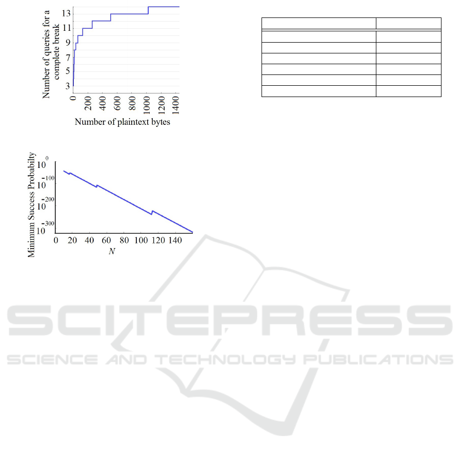
Figure 2: Number of required queries for a complete break.
Figure 3: Log scale curve of the minimum success proba-
bility of an adversary who uses at most dlog
2
(8N+16)e−1
queries.
communications, which require a high level of effi-
ciency. The computational complexity of the integrity
protection algorithm is the summation of complexi-
ties of the 16-bit Fletcher checksum generation and
the bit permutation process. Given an array of length
n, the complexity of computing the 16-bit Fletcher
checksum is α ·n, where α is a constant. The compu-
tational complexity of the bit permutation process is
the sum of complexities of the pseudo-random num-
ber generation and the radix sorting procedure. The
computational complexity of generating n pseudo-
random numbers using a linear congruential genera-
tor is β ·n, where β is a constant. In addition, given an
array of length n, radix sorting rearranges the array in
linear time. Therefore, in the worst case, a permuta-
tion of an array with length n is achieved using µ ·n
computations, where µ is a constant. Accordingly, the
computational complexity of the integrity protection
algorithm is (α + β + µ) ·n.
Given that the maximum size of payload data is
1492 bytes, a feasible integrity protection method
should have a minimum throughput of higher than
373 kilobytes per second (KB/s). This allows par-
ties to communicate reliably within the maximum
acceptable latency (4 ms). Since the most re-
cent microprocessors in substation automation sys-
tems use ARM Cortex-M processor cores, we eval-
uated the throughput of the integrity protection al-
gorithm on an ARM Cortex-M0 platform with 48
Table 5: Algorithm performance comparison.
Algorithm Speed (KB/s)
Proposed method 424
MD5 147
ChaCha20-Poly1305 94
AES-128-CCM 70
AES-128-EAX 70
AES-128-GCM 41
MHz frequency. We used K = (1,2, 3) as a rep-
resentative key for the performance analysis. We
also compared our performance results with that of
MD5, ChaCha20-Poly1305, AES-128-CCM, AES-
128-EAX, and AES-128-GCM on the same platform
(Birr-Pixton, 2015; Mouha et al., 2014). The bench-
mark results on an ARM Cortex-M0 microprocessor
are shown in Table 5. Benchmarks show that all meth-
ods have the same computational complexity O(n),
where n is the number of message bytes. O(n) gives
an asymptotic bound c ·n, which describes a linear
growth for a significantly large n. However, since n
is bounded, the constant factor c makes a difference
in running time. Compared to previous schemes, as
confirmed by the run-time analysis shown in Table
5, the proposed integrity protection method is much
faster, and it is the only scheme that meets the mini-
mum speed requirement, that is, 373 KB/s. This fast
integrity checking opens the use of energy anomaly
detection methods when multiple message exchange
is required.
6 CONCLUSION
In this paper, we proposed a lightweight and se-
cure integrity protection algorithm for maintaining
the integrity of PMU data in protective relaying ap-
plications. To be more precise, our proposed algo-
rithm is used in the absence of integrity protection
in IEC 61850-90-5, when the HMAC identifier is
set to zero. The proposed method computes a 16-
bit Fletcher checksum of the payload data, embeds
it into the payload data, and then, shuffles the pay-
load bits using a fast permutation-only encryption
scheme. We analyzed the security of our method with
respect to a query adversary. Our analysis showed
no weaknesses in the proposed method, and demon-
strated no simple method of recovering the secret key.
It also confirmed the security of the proposed in-
tegrity protection method against ciphertext-only at-
tacks and known/chosen plaintext attacks. A com-
parison with a number of existing integrity protection
methods showed that despite having the same level of
computational complexity, the proposed method is
SECRYPT 2017 - 14th International Conference on Security and Cryptography
40

much faster, and it is the only integrity protection
scheme that meets the speed requirement.
Since the proposed integrity protection method
uses a symmetric encryption algorithm, its security
highly depends on the initial key agreement, rekey-
ing, and revocation. To this end, our future research
will be focused on secure and efficient key manage-
ment between PMUs and PDCs in transmission and
distribution substations.
REFERENCES
Abuadbba, A. and Khalil, I. (2015). Wavelet based stegano-
graphic technique to protect household confidential
information and seal the transmitted smart grid read-
ings. Information Systems, 53:224–236.
Abuadbba, A., Khalil, I., Ibaida, A., and Atiquzzaman, M.
(2016). Resilient to shared spectrum noise scheme for
protecting cognitive radio smart grid readings- BCH
based steganographic approach. Ad Hoc Networks,
41:30–46.
Adamiak, M., Schiefen, M. J., Schauerman, G., and Ca-
ble, B. (2014). Design of a priority-based load shed
scheme and operation tests. IEEE Transactions on In-
dustry Applications, 50(1):182–187.
Barker, E., Barker, W., Burr, W., Polk, W., and Smid, M.
(2016). Recommendation for key management part
1: General (revision 4). NIST special publication,
800(57).
Bellare, M., Goldwasser, S., and Micciancio, D. (1997).
“pseudo-random” number generation within crypto-
graphic algorithms: The DDS case. In Annual In-
ternational Cryptology Conference, pages 277–291.
Springer.
Birr-Pixton, J. (2015). Benchmarking mod-
ern authenticated encryption on e1 devices.
https://jbp.io/2015/06/01/modern-authenticated-
encryption-for-1-euro/.
Briat, C. (2011). Convergence and equivalence results for
the Jensen’s inequality–Application to time-delay and
sampled-data systems. IEEE Transactions on Auto-
matic Control, 56(7):1660–1665.
Cogranne, R. and Retraint, F. (2013). An asymptotically
uniformly most powerful test for LSB matching de-
tection. IEEE transactions on information forensics
and security, 8(3):464–476.
Cohen, A. S. and Lapidoth, A. (2002). The gaussian wa-
termarking game. IEEE Transactions on Information
Theory, 48(6):1639–1667.
Dworkin, M. J. (2007). Recommendation for block cipher
modes of operation: The CMAC mode for authenti-
cation. NIST special publication 800-38b, National
Institute of Standards and Technology (NIST).
Fan, Y., Zhang, Z., Trinkle, M., Dimitrovski, A. D., Song,
J. B., and Li, H. (2015). A cross-layer defense mecha-
nism against GPS spoofing attacks on PMUs in smart
grids. IEEE Transactions on Smart Grid, 6(6):2659–
2668.
Gilad, Y. and Herzberg, A. (2014). Off-path TCP injection
attacks. ACM Transactions on Information and Sys-
tem Security (TISSEC), 16(4):13.
Guo, H., Li, Y., and Jajodia, S. (2007). Chaining wa-
termarks for detecting malicious modifications to
streaming data. Information Sciences, 177(1):281–
298.
IEC 61850-90-5 (2012). Use of IEC 61850 to transmit syn-
chrophasor information according to IEEE C37. 118.
Khan, E., El-Kharashi, M. W., Gebali, F., and Abd-El-Barr,
M. (2007). Design and performance analysis of a uni-
fied, reconfigurable HMAC-Hash unit. IEEE Trans-
actions on Circuits and Systems I: Regular Papers,
54(12):2683–2695.
Krawczyk, H. (2001). The order of encryption and authenti-
cation for protecting communications (or: How secure
is SSL?). In Annual International Cryptology Confer-
ence, pages 310–331. Springer.
Kundu, P. and Pradhan, A. K. (2014). Synchrophasor-
assisted zone 3 operation. IEEE Transactions on
Power Delivery, 29(2):660–667.
L’Ecuyer, P. and Simard, R. (2007). TestU01: A C li-
brary for empirical testing of random number gener-
ators. ACM Transactions on Mathematical Software
(TOMS), 33(4):22.
Martin, K., Hamai, D., Adamiak, M., Anderson, S., Be-
govic, M., Benmouyal, G., Brunello, G., Burger, J.,
Cai, J., Dickerson, B., et al. (2008). Exploring the
IEEE standard C37. 118–2005 synchrophasors for
power systems. IEEE transactions on power delivery,
23(4):1805–1811.
Martin, K., Zwergel, A., and Kapostasy, D. (2015).
PMU installation and configuration requirements,
Public Manual, version no. 1.0, MISO energy.
https://www.misoenergy.org/Library/Repository/.
Mouha, N., Mennink, B., Van Herrewege, A., Watanabe, D.,
Preneel, B., and Verbauwhede, I. (2014). Chaskey: an
efficient MAC algorithm for 32-bit microcontrollers.
In International Workshop on Selected Areas in Cryp-
tography, pages 306–323. Springer.
Nakassis, A. (1988). Fletcher’s error detection algorithm:
how to implement it efficiently and how to avoid the
most common pitfalls. ACM SIGCOMM Computer
Communication Review, 18(5):63–88.
Oechslin, P. (2003). Making a faster cryptanalytic time-
memory trade-off. In Annual International Cryptol-
ogy Conference, pages 617–630. Springer.
Pappu, V., Carvalho, M., and Pardalos, P. (2013). Opti-
mization and security challenges in smart power grids.
page 157. Springer.
Plumstead, J. B. (1983). Inferring a sequence generated
by a linear congruence. In Advances in Cryptology–
CRYPTO, pages 317–319.
Rosenbaum, U. (1993). A lower bound on authentication
after having observed a sequence of messages. Jour-
nal of Cryptology, 6(3):135–156.
Seyed Reza, F., Vanfretti, L., Ruiz-Alvarez, A., Mahmood,
F., Hooshyar, H., and Cairo, I. (2016). An IEC 61850-
90-5 gateway for IEEE C38. 118.2 synchrophasor data
transfer. In IEEE PES General Meeting, 17th to 21th
A Lightweight Integrity Protection Scheme for Fast Communications in Smart Grid
41

of July, 2016. Institute of Electrical and Electronics
Engineers (IEEE).
Sobolewski, J. S. (2003). Cyclic redundancy check. In En-
cyclopedia of Computer Science, pages 476–479. John
Wiley and Sons Ltd.
Sofia, A., Lewis, C., Jacobi, C., Jamsek, D. A., Riedy,
D. F., Vogt, J.-S., Sutton, P., and John, R. S. (2015).
Integrated high-performance data compression in the
IBM z13. IBM Journal of Research and Development,
59(4/5):7–1.
Weng, Y., Negi, R., Faloutsos, C., and Ili
´
c, M. D. (2016).
Robust data-driven state estimation for smart grid.
IEEE Transactions on Smart Grid, pages 1–12.
Wetterwald P. and Raymond J. (2015). Deterministic net-
working utilities requirements, IETF draft, detnet.
Zander, S., Armitage, G., and Branch, P. (2007). A survey
of covert channels and countermeasures in computer
network protocols. IEEE Communications Surveys &
Tutorials, 9(3):44–57.
Zhang, W., Liu, Y., Das, S. K., and De, P. (2008). Secure
data aggregation in wireless sensor networks: a water-
mark based authentication supportive approach. Per-
vasive and Mobile Computing, 4(5):658–680.
SECRYPT 2017 - 14th International Conference on Security and Cryptography
42
