
SystemC Test Case Generation with the Gazebo Simulator
Thomas W. Pieber, Thomas Ulz and Christian Steger
Institute for Technical Informatics, Graz University of Technology, Inffeldgasse 16/I, Graz, Austria
Keywords:
SystemC, Gazebo, Plugin, Cosimulation, Simulation, XML, Test Case Generation.
Abstract:
The current approach of hardware simulators are testbeds that supply the Device under Test (DUT) with inputs.
These sequences of inputs are the result of engineers reverse engineering the use cases extracting the inputs
from them and adding some extreme cases. This paper describes an approach where the input sequences are
generated directly from the use case itself. The use case is therefore simulated in an environmental simulator
such as Gazebo. This generates the stimuli for the DUT. To facilitate the compatibility between the different
simulation environments we present an easy-to-use and easy-to-implement communication strategy.
1 INTRODUCTION
A system design needs to be simulated in order to
test it extensively. Such a simulation should be stimu-
lated with real world events and unusual events to test
the functionality under normal working situations and
extreme cases. Such tests are normally designed by
thinking of scenarios, defining how the device should
react, and testing these input sequences. Furthermore,
random input sequences can be applied to the sys-
tem to test the design more extensively. These ran-
dom tests are unlikely to produce valid inputs and pri-
marily test the error handling. As these tests are un-
likely to perform useful tasks, it is necessary to have
a system that can generate useful input and the ac-
cording expected data. We have therefore designed a
system that uses an environment simulation to gener-
ate the inputs for testing a sensor system. This de-
sign can also reduce the effort needed to design test
cases, as only scenarios in which the DUT normally
operates need to be constructed. From these scenar-
ios valid input data is automatically generated. As an
environmental simulator, a robotics simulator, such as
Gazebo, can be used.
A robotics simulator is designed to handle com-
plex systems and generate sensory information of any
kind. A widely used robotics simulator is the Gazebo
simulator (Open Source Robotics Foundation, 2004;
Koenig and Howard, 2004). This open source product
can be modified (in a, for us, useful way) by writing
plugins for the entire world, the models, the sensors,
and an entire system. Further modifications can be
made to the visuals and the GUI. The Gazebo simu-
lator operates in discrete time steps of 1 ms . This is
enough for simulating the movement of a robot and
scarce enough that the robot’s operating system can
handle most commands in this time step.
For simulating a sensory device (hereafter Device
under Test or DUT) a tool like SystemC (Accelera,
2000) can be used. With this simulator, a complex mi-
crosystem can be designed and tested. Also the com-
ponent parts of this system can be modelled in varying
detail, allowing for later synthetization. SystemC can
simulate the DUT in discrete time intervals as small
as 1 fs.
This difference in simulation speed is a major
problem to be solved to combine the two simulation
environments. As the SystemC simulation is operates
in such fine time intervals, it generates huge amounts
of data during the execution of a test scenario, as such
a test scenario can last for many minutes. The prob-
lem of generating and handling these amounts of data
must be considered when designing the status output
of the DUT. Also the connection of the DUT on the
SystemC side of the simulation needs to be modified
in order to allow the storage of communication data
between it and the simulator and the correct input of
the data to the DUT.
Another issue that comes with connecting the
simulators comes from the communication between
them. The simulators have to communicate in order
to exchange status information like the actual simu-
lation time, commands, and generated messages. As
the SystemC simulation works with finer time steps it
requires much more fine granular input data and pro-
duces huge amounts of output data. This data needs
Pieber, T., Ulz, T. and Steger, C.
SystemC Test Case Generation with the Gazebo Simulator.
DOI: 10.5220/0006404800650072
In Proceedings of the 7th Inter national Conference on Simulation and Modeling Methodologies, Technologies and Applications (SIMULTECH 2017), pages 65-72
ISBN: 978-989-758-265-3
Copyright © 2017 by SCITEPRESS – Science and Technology Publications, Lda. All rights reserved
65

to be extrapolated from the data Gazebo provides and
afterwards filtered to allow Gazebo to work with the
return data.
The remainder of this paper is structured as fol-
lows: In Section 2 other works that combine SystemC
or Gazebo with other simulators are described. Sec-
tion 3 explains the motivation for our design, the re-
quirements that need to be implemented, and details
of the solution for the requirements. An evaluation
of the usability and functionality of the design is de-
scribed in Section 4. Following that, Section 5 men-
tions ideas on how to further improve the proposed
design. This paper concludes with Section 6.
2 RELATED WORK
Gazebo is an open source robotics simulator. It is
primarily combined with the Robot Operating Sys-
tem (ROS). There are some approaches for combining
Gazebo with other software for robotics and compu-
tational intelligence (Zamora et al., 2016).
There are approaches that connect other tools that can
be used to simulate hardware, to Gazebo (Mathworks,
2016). In these approaches, the main interface to the
simulation environment is the interface to ROS.
SystemC is a modelling language based on C++.
The extension consists of a class library and a simu-
lation kernel. In (Panda, 2001) a short summary of
design processes for SystemC is given.
There exist some interfaces to SystemC in the lit-
erature such as (Martin et al., 2002; Possadas et al.,
2005; Bouchhima et al., 2006; Huang et al., 2008;
Mueller-Gritschneder et al., 2013). These papers use
SystemC as a primary basis and extend the function-
ality of it. (Huang et al., 2008) describe a possibility
of running a SystemC simulation on a distributed net-
work, improving the time performance significantly.
An interface to SystemC was designed in (Bouch-
hima et al., 2006). This work uses Matlab/Simulink
as a continuous simulation for the environment, which
communicates with the SystemC model.
In the work found in (Martin et al., 2002),
SystemC was connected with an analog circuit simu-
lator like SPICE (Simulation Program with Integrated
Circuit Emphasis) and VHDL (Very High Speed Inte-
grated Circuit Hardware Description Language (VH-
SIC Hardware Description Language)).
In (Mueller-Gritschneder et al., 2013) a platform
for simulating an entire robot is modelled in SystemC.
In this approach the SystemC simulation was used
to simulate the behaviour of a robotic system on the
transaction layer. With their simulation results the au-
thors update the model of a robot in a virtual world,
simulated in a Java environment. After that measure-
ments are taken in the Java environment and sent to
the SystemC robot model for further processing. They
use network sockets to communicate between the two
simulations. In this paper SystemC was used to sim-
ulate the robot’s movement as accurate as possible,
while in our proposal the robot’s behaviour gives the
input to the simulation of other hardware.
In summary, SystemC was connected with many
simulators for cycle accurate measurements, other
hardware description languages, or circuit simulators.
In (Mueller-Gritschneder et al., 2013) SystemC was
used to simulate physical effects on robots.
Comparing this previous work with our proposal,
our contributions are a completely new aspect of
connecting simulators for generating test cases for
systems automatically, as well as connecting the
SystemC simulation with an open source robotics
simulation. That means that SystemC was previously
used to simulate effects in the larger simulation, in
this approach the larger simulation is used to stimu-
late the whole system simulated in SystemC.
In our use-case a sensor is read using a wireless
channel. For such a use-case the NFC technology is
well well-suited. This is due to the fact that energy
can be transmitted through the RF (radio frequency)
field. With that energy the sensor and the supporting
microcontroller(s) can be operated. The same energy
can also be used to charge a small battery or capacity.
In (Wireless Power Consortium et al., 2010; Strom-
mer et al., 2012; Lee et al., 2013) the mechanism for
transmitting energy alongside data and for storing that
energy are described.
There are different approaches to communicate
between simulation environments; commonly used
are XML (Extensible Markup Language) and JSON
(JavaScript Object Notation). Of these two, JSON
is more efficient as (Nurseitov et al., 2009) show.
(Sumaray and Makki, 2012) furthermore compares
Google’s Protocol Buffer (protobuf), which is used by
the Gazebo simulator, alongside JSON and XML.
As the SystemC simulation works in many cycles
for every internal time step, the efficient generation of
JSON objects, as well as the generation of protobuf-
messages, would require major changes in the exist-
ing simulations. Following this, the approach to com-
municate from SystemC to Gazebo is to embed the
values of interest in XML-tags.
3 DESIGN
The goal of the presented design is to connect a
SystemC simulation to a high-level simulator in order
SIMULTECH 2017 - 7th International Conference on Simulation and Modeling Methodologies, Technologies and Applications
66
to generate stimuli for the simulation. Using this ap-
proach, the testbed for the SystemC simulation is the
simulation of the use-case. This method allows the
generation of stimuli for the SystemC simulation from
the specification of an interaction of the designed sys-
tem with the environment. This is not only more effi-
cient than a system engineer could be, but also small
variations of the environment can generate a wide va-
riety of tests.
To support a SystemC simulation with input from
an environment simulator like Gazebo, a plugin for
that simulator needs to be developed. This plugin
must be able to send commands and data to the
SystemC environment and receive the results and sta-
tus of the SystemC simulation.
A huge hurdle for connecting the two simula-
tion environments is the different simulation speeds.
Gazebo works with time steps of 1 ms whilst SystemC
can handle steps as small as 1 fs. This is a twelve or-
ders of magnitude higher time resolution of SystemC.
Even a “slow” computer which only works at 50 MHz
performs 5·10
4
steps in one time step of Gazebo. This
results in amounts of data that are hard to evaluate in
a high-level simulation environment. Therefore, mea-
sures have to be made to limit the amount of data that
needs to be transmitted. In order to do this a connec-
tion between the simulators needs to be defined.
The connection between the two simulation envi-
ronments must be supported by both environments. In
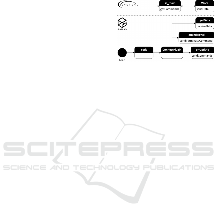
the Gazebo simulator a plugin can be written. Figure
1 shows a subset of the states the plugin needs to per-
form during the execution. This model-plugin needs
to open communication channels and fork a new pro-
cess that will become the SystemC simulation. The
plugin then proceeds to the normal execution. For
that it connects to the required Gazebo internal sig-
nals. One of the required connections is to the onUp-
date signal. This signal is set on every time step in
the simulation. On activation of this signal the plugin
retrieves the status information and other messages
from the DUT in the SystemC simulation. When this
is done and the data is processed, the plugin can send
new commands and messages to the DUT.
To send different messages between the communi-
cating parties an easy-to-implement approach is used.
In the SystemC simulation the interesting parameters
can be sent to the communication channel. The quick-
est way to implement such a communication would
be to redirect the standard output to the communi-
cation pipe before forking the SystemC simulation,
and send the interesting values encased by XML-style
tags. With these tags it is easy to find the interest-
ing values in the input stream and separate it from
the rest. With this approach the produced data can
Figure 1: States of the execution of the implemented plugin.
be collected by Gazebo in the order it was produced.
Another approach is the collection of the interesting
data in a global data structure, generate a JSON mes-
sage, and send it at the end of the time step. This
approach however would require more changes in the
simulation, while the improvement of the efficiency is
negligible in contrast to the whole execution.
The Gazebo plugin needs to parse the incoming
stream of data. With the XML-tags it can detect the
values, perform some preprocessing and store it in a
fitting datastructure. When the simulation halts at the
specified time, a sync tag needs to be sent to Gazebo.
When this signal is received, the plugin can operate
again and send the received data to the processing
nodes. As (Sumaray and Makki, 2012) show, this
communication is done most efficiently with Google’s
protobuf approach. To use this method, custom mes-
sages are defined. These messages can then be sent
to a simulation of the channel. This separation is
done in order to provide the possibility of changing
the channel and the parameters independently of the
rest. In our design a NFC communication is chosen.
The channel simulation is implemented as a World-
plugin of Gazebo. This plugin takes the environmen-
tal states and calculates the transmitted power and can
induce errors or attacks on the communication. The
calculations of the transmission statistics are based on
(Wireless Power Consortium et al., 2010; Lee et al.,
2013) The channel plugin can then relay the (modi-
fied) messages with additional information about the
channel to the receiving party. In our scenario, the
ROS system can then access the received data.
The communication in the other direction follows
the same rules. The robot’s OS sends data to the chan-
nel, the channel modifies and appends the message
and retransmits it to the sensor plugin (if the sensor
is within communication range). The sensor plugin
gathers the data and commands from the robot and
from the channel, and generates a message that can
be sent to the SystemC simulation.
Another useful extension is another World-plugin
SystemC Test Case Generation with the Gazebo Simulator
67

that gatheres sensory information for the sensor to
process. Also this information can be collected by the
sensor plugin and relayed to the SystemC simulation.
In the SystemC simulation the testbed needs to be
changed to accommodate the interface to the high-
level Gazebo simulation. The requirements that the
altered testbed has to fulfil, in order to work properly,
are:
R.1 The simulation parameters, commands to the
DUT, and other information regarding the hard-
ware simulation must be configurable.
R.2 The commands that come from the Gazebo sim-
ulator must be parsed and distributed.
R.3 The testbed must be able to be activated contin-
uously.
R.4 The simulation time for each iteration should be
variable to allow a variety of scenarios.
R.5 A direct communication to the parts that can be
affected by the commands must be possible.
R.6 The incoming commands must be stored and ex-
ecuted in the correct order.
R.7 A proper time synchronization between the two
environments needs to be established.
R.8 The traces from the simulation should be de-
activated, or at least reduced, as a execution
over a prolonged simulation time produces huge
amounts of data.
Furthermore, some minor changes have to be made in
the rest of the simulation. Most notably is the inser-
tion of messages back to the Gazebo simulator. These
changes are similar to the changes needed for require-
ment R.7.
Requirement R.1 is fulfilled by providing a
POSIX (Portable Operating System Interface) pipe
that connects the standard input of the SystemC
testbed with the Gazebo plugin. This allows the
transfer of information (like configuration parame-
ters) through the standard input from the Gazebo sim-
ulator to the SystemC simulation.
To satisfy requrement R.2 a parser for the received
messages is implemented and called at the start of ev-
ery execution cycle.
To fulfil requirement R.3 the testbed is written in
an endless loop. The condition to terminate the pro-
cess is taken from the standard input. As the input
is connected via a POSIX pipe to the Gazebo simula-
tor, the SystemC simulation can be ended if Gazebo
is closed.
Special commands to change timing parameters
are included in the command structure to implement
requirement R.4. In SystemC two commands are
needed; one for the time unit and one for the value.
As we want to simulate a sensor system, it is use-
ful to feed the simulated sensory information to the
sensor-input of the SystemC simulation. This cor-
responds to specification R.5. With special tags this
data can be extracted from the received message. This
data is then sent to a FIFO (first in, first out) memory
“sensor”. This sensor can then set the required values
on its data lines.
The same approach can be used for requirement
R.6. In this requirement the input is stored in a FIFO
at the control unit of the sensor. This control unit can
then execute the commands in order. For a proper
execution of the commands an additional data field is
required. This data field stores the exact time values at
which the command should have arrived to simulate a
serialized channel.
To fulfil requirement R.7, a channel to communi-
cate back to the Gazebo simulation needs to be de-
clared. This is most easily done by redirecting the
standard output to another pipe before executing the
simulation. The synchronization between the simu-
lation environments is done by creating a sync-signal
at the end of a simulation step. The sync-signal is de-
fined by a specialized XML-tag that is sent to the stan-
dard output. After this signal is received, the Gazebo
simulator is allowed to excite another step. This step
in turn triggers the advance of the SystemC simulation
by one time step. The same method for communicat-
ing to the Gazebo environment can be used for other
data as well. These data-fragments are then encased
in XML-tags that can be found in the output stream
of the SystemC simulation. For each interesting event
in the SystemC environment a separate XML-tag is
defined. In our test-design, interesting events are: (I)
the sending of data packets from different execution
stages and (II) the status of the battery of the sensor.
When simulating an environment it is necessary
that longer amounts of time are simulated, in order
to also simulate the edge conditions. This results in
huge amounts of data that come from the SystemC
environment. Normally, this data comes in form of
VCD-files (Value Change Dump files). If the clock of
the simulation is dumped as well, this results in vast
amounts of data referring to clock changes while the
actual simulation process has not even begun.
Requirement R.8 refers to that problem. There-
fore it is necessary to wait for input before initializing
the simulation. This input determines if traces will
be made, and if yes, which traces should be activated.
Furthermore, it is possible to pause the execution of
the SystemC simulation if all relevant operations for
this time step are handeled which results in shorter
simulation times. This approach does however reduce
the quality of the simulation results and should there-
SIMULTECH 2017 - 7th International Conference on Simulation and Modeling Methodologies, Technologies and Applications
68
Figure 2: Overall communication process between Gazebo
and SystemC.
fore only be used if the DUT is in a low power mode.
If the simulation is paused prematurely two addi-
tional challenges emerge. The first is the disconnec-
tion of the simulation time of Gazebo and SystemC.
In order to prevent that from happening in the trace,
an additional value can be generated. This value is
toggled if the simulation pauses prematurely.
The second challenge is the simulation of values
that change even if basically no useful operation is
performed. An example for such a value is the energy
level of a battery that is drained a little even in low-
power mode. A fashionable solution to this problem
is the estimation of this value at the supposed end of
the simulation.
With these calculations at the premature pausing
of the simulation and the knowledge that every sim-
ulation step takes 1 ms the timings of the operations
can be restored and the sharp edges on estimated val-
ues can be reduced by interpolating between the data
points.
Figure 2 shows the global communication paths
between the two simulation systems and the changed
interfaces. The robot from the Gazebo simulator, as
well as the environment in which the robot operates,
compute the input for the SystemC simulation. These
input parameters are sent to the interface (testbed) of
the SystemC simulation, which in turn distributes this
data to the required parts of the internal simulation.
This simulation produces outputs which are sent over
the standard output to the Gazebo simulator (dashed
line). Furthermore, data is sent to the testbed, as some
traces still need to be captured. In the Gazebo simu-
lator, the environment can affect the communication
channel between the sensor and the robot again. Fi-
nally, the robot can access the gathered data. This data
can then be compared to the data generated by the sen-
sor in order to optimize the communication process.
All parts of the simulation in the Gazebo simulator
are implemented using plugins. This allows the easy
reconfiguration of the simulation to feature other or
more actors, inputs, obstacles, parameters, and even
allows the change of the whole communication chan-
nel.
4 EVALUATION
To evaluate the developed system, a SystemC simula-
tion of a smart sensor that communicates and charges
the internal battery with NFC (Near Field Commu-
nication) technology was constructed. This is the
sensory device denoted DUT beforehand. This sim-
ulation is then started by a Gazebo plugin. The
Gazebo simulator provides the context for the sim-
ulation and gives useful sensory values as input to
the system. The Gazebo simulator can communicate
with the SystemC simulation over the standard input
and output of the SystemC simulation. In our design
the wireless NFC communication channel is modelled
in a Gazebo World-plugin. A World-plugin is a plu-
gin, that is loaded at the beginning, connected to all
parts of the simulation, and is active until the simu-
lation ends. With this approach, the channel simula-
tion can get different parameters that affect the com-
munication. Such parameters are the distance and
orientation between the antennas, obstacles between
the antennas, and other noise on the communication
band. Because the channel is modelled separately, it
can be easily changed to accommodate other commu-
nication techniques like WiFi, Bluetooth, Zigbee, or
wired connections.
The communication between the simulators is per-
formed with strings encased in XML-tags. On each
side of the communication an XML parser is written
that searches for the declared tags. The strings found
by this parser are then stored in a suiting data struc-
ture. For our use case, this data structure consists of
a list of objects, referring to the XML-tags, each con-
taining a list of the received data values.
The data contained in this structure can then be
read sorted by topic in the order it was received. For
data that needs to be transmitted via the NFC chan-
nel, a preprocessing step is executed that generates
protobuf-messages.
The SystemC simulation can get the required
stimuli from the environment of the Gazebo simula-
tor. In Figure 3 a concept for the simulation is shown.
The robot, as part of the environment, interacts with
the DUT. In this simulation the DUT is attached to a
crate as an environmental feature. The robot moves
SystemC Test Case Generation with the Gazebo Simulator
69
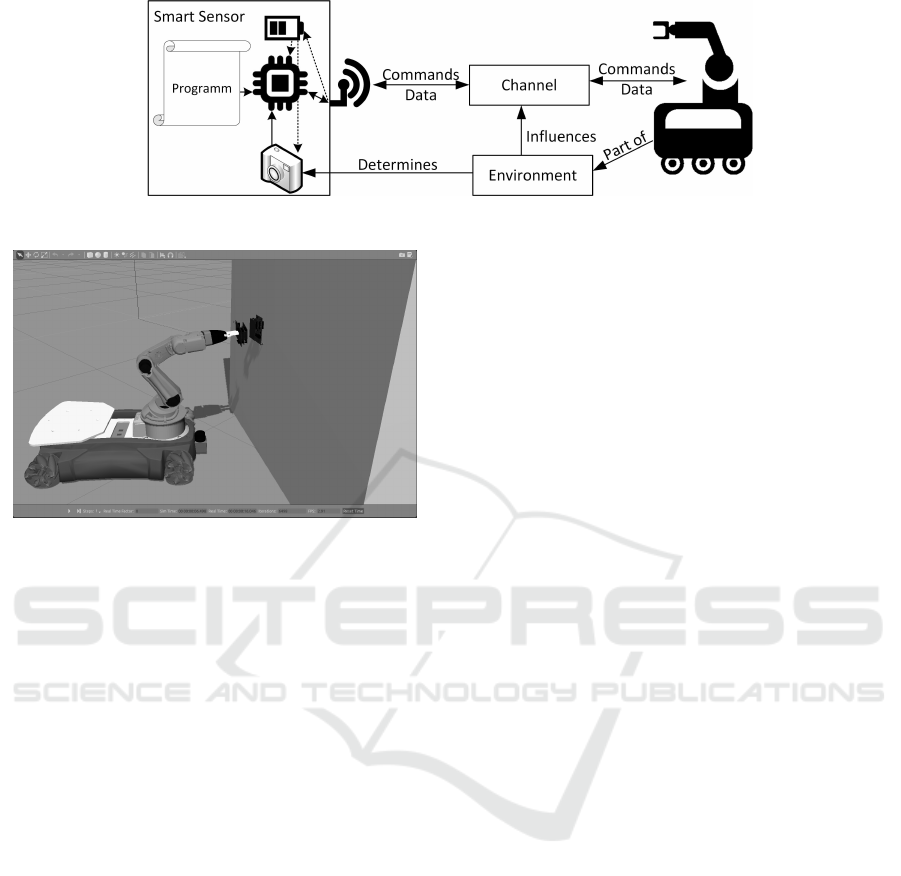
Figure 3: Concept of the Evaluation Design.
Figure 4: Interaction of a robot with the sensor.
towards the DUT and tries to communicate with it.
As the robot gets closer, the NFC connection between
the robot and the DUT gets better. When the channel
is good enough such that enough energy gets trans-
mitted the DUT switches on and the communication
can happen.
This simulation performs every operational phase
of such a DUT when some entity tries to communi-
cate with it. Because the global simulation is done
in a robotics simulator, a new test case can be imple-
mented by repositioning the DUT and robot and giv-
ing the robot some new instructions. The local sim-
ulation of the DUT is still done with SystemC. This
allows very accurate measurements on the DUT. In
this scenario we want to monitor the power usage and
ability to store excess energy during such a read cy-
cle. With these measurements we hope to develop a
more efficient power manage system on our DUT. Ad-
ditionally more information about the NFC communi-
cation can be gathered from this simulation.
Figure 4 shows the environment with the robotic
arm and the DUT. To communicate with the DUT an-
other sensor was mounted on the end of the robotic
arm.
While the robot is approaching the sensor the NFC
antenna on the robot’s arm is activated. The trans-
mitted energy and commands are received at the sen-
sor. The sensor’s energy intake can be seen in Figure
5. This figure furthermore shows the compression of
simulation time as a result of requirement R.8. The
upper graph starts at approximately 0.9 ms and runs
to about 3.5 ms. The lower graph is time-expanded to
correlate with the Gazebo simulation time. This graph
starts at 5840 ms and runs to 6480 ms. This results in
a compression of the 5.8 s idle time to 0.9 ms.
5 FUTURE WORK
As many hardware elements are simulated in lan-
guages other than SystemC, plugin-structures need to
be developed to also include such simulations with a
high-level simulator. From our point of view a simi-
lar approach to include languages such as Verilog or
VHDL seems promising.
For bigger simulations it may also be useful to
connect to the SystemC simulation using network
sockets to allow the parallel computation of multiple
sensors.
Furthermore, simulations of the planned system as a
whole, of multiple sensors, senders and receivers, and
different channels need to be performed.
6 CONCLUSIONS
We presented a new approach for connecting a
SystemC hardware simulation to a robotic simula-
tor. This is done in order to automatically generate
the stimuli for the SystemC testbed. The huge dif-
ference in time resolution between these simulators
pose a barrier to connect them. To solve this hur-
dle, a mechanism to synchronize the simulations and
transport data between them is shown. In addition to
that, we have mentioned that extrapolating data for the
SystemC simulation, as well as filtering the produced
data for the Gazebo simulator, is necessary. Further-
more, the SystemC simulation needs some changes in
order to be able to connect to such a high-level simu-
lator. These changes include:
• Reduction of output if possible - without greatly
decreasing the degree of detail where it is needed.
SIMULTECH 2017 - 7th International Conference on Simulation and Modeling Methodologies, Technologies and Applications
70
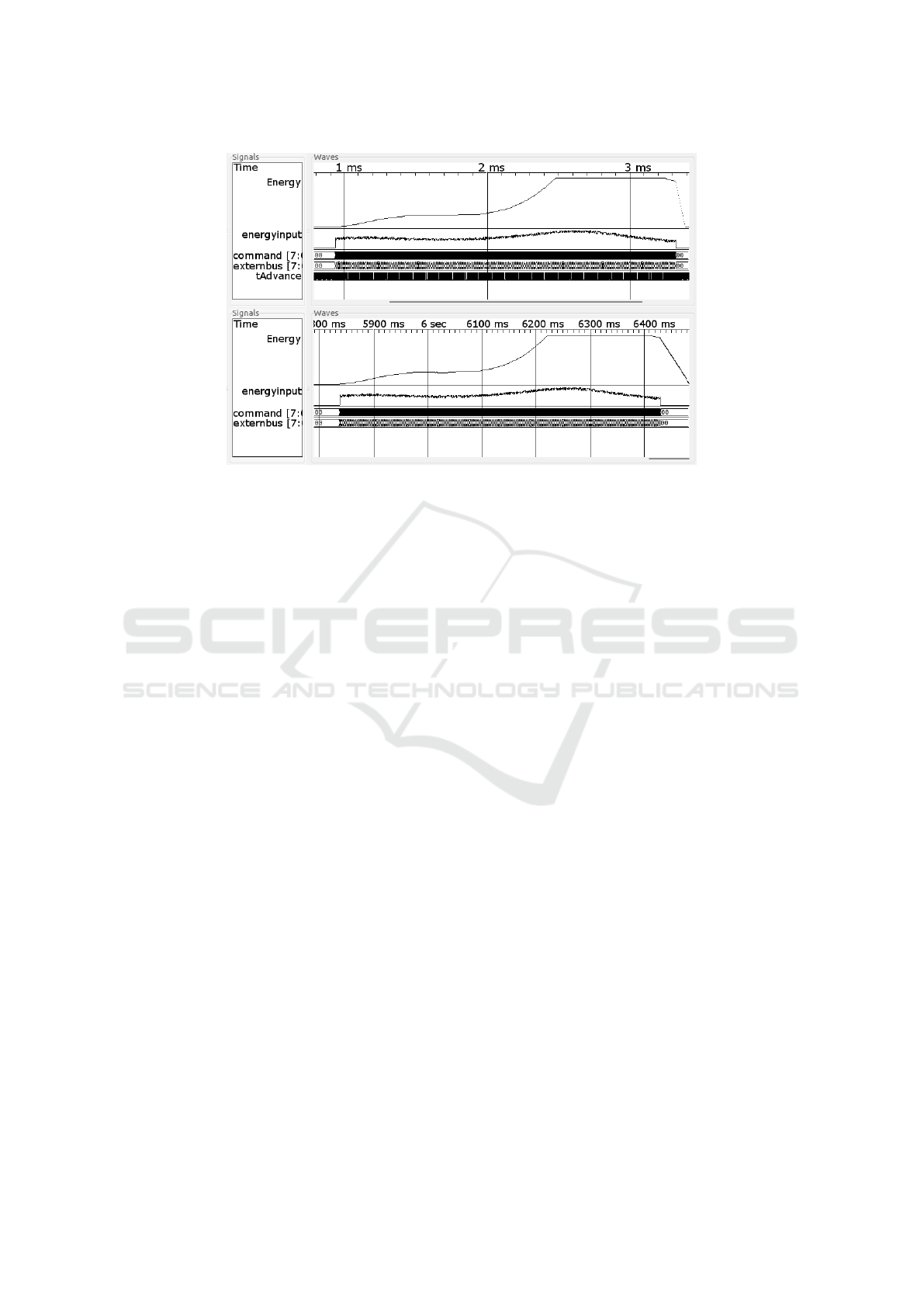
Figure 5: Energy trace of the sensor while a robot is approaching. The shorter simulation time at the top is a result of the
reduction of execution time due to requirement R.8
• Rewriting the testbed to allow the external simu-
lation to control the simulation
• Inclusion of special outputs for synchronization,
passing status information, and transmitting the
generated data to the Gazebo simulator.
Additional changes have been made to the Gazebo
simulator.
• A plugin to control SystemC has been developed.
This plugin handles all communication from and
to SystemC, keeps the simulations synchronized,
and controls the start and end conditions for the
SystemC simulation.
• Different channels, wireless and wired, have been
modelled in Gazebo that can be used to simulate
the connection between arbitrary devices.
ACKNOWLEDGEMENTS
This project has received funding from the Electronic
Component Systems for European Leadership Joint
Undertaking under grant agreement No 692480. This
Joint Undertaking receives support from the European
Unions Horizon 2020 research and innovation pro-
gramme and Germany, Netherlands, Spain, Austria,
Belgium, Slovakia.
REFERENCES
Accelera (2000). SystemC. http://accellera.org/downloads/
standards/systemc. Last accessed on Jan 17, 2017.
Bouchhima, F., Briere, M., Nicolescu, G., Abid, M., and
Aboulhamid, E. (2006). A SystemC/simulink co-
simulation framework for continuous/discrete-events
simulation. In 2006 IEEE International Behavioral
Modeling and Simulation Workshop. Institute of Elec-
trical and Electronics Engineers (IEEE).
Huang, K., Bacivarov, I., Hugelshofer, F., and Thiele, L.
(2008). Scalably distributed SystemC simulation for
embedded applications. In 2008 International Sym-
posium on Industrial Embedded Systems. Institute of
Electrical and Electronics Engineers (IEEE).
Koenig, N. and Howard, A. (2004). Design and use
paradigms for gazebo, an open-source multi-robot
simulator. In 2004 IEEE/RSJ International Confer-
ence on Intelligent Robots and Systems (IROS) (IEEE
Cat. No.04CH37566). Institute of Electrical and Elec-
tronics Engineers (IEEE).
Lee, W.-S., Son, W.-I., Oh, K.-S., and Yu, J.-W. (2013).
Contactless energy transfer systems using antiparallel
resonant loops. IEEE Transactions on Industrial Elec-
tronics, 60(1):350–359.
Martin, D., Wilsey, P., Hoekstra, R., Keiter, E., Hutchinson,
S., Russo, T., and Waters, L. (2002). Integrating mul-
tiple parallel simulation engines for mixed-technology
parallel simulation. In Proceedings 35th Annual Simu-
lation Symposium. SS 2002. Institute of Electrical and
Electronics Engineers (IEEE).
Mathworks (2016). Get Started with Gazebo and a Sim-
ulated TurtleBot. https://de.mathworks.com/help/
robotics/examples/get-started-with-gazebo-and-a-
simulated-turtlebot.html. Last accessed on Jan 03,
2017.
Mueller-Gritschneder, D., Lu, K., Wallander, E., Greim, M.,
and Schlichtmann, U. (2013). A virtual prototyping
platform for real-time systems with a case study for
a two-wheeled robot. In Design, Automation & Test
SystemC Test Case Generation with the Gazebo Simulator
71

in Europe Conference & Exhibition (DATE), 2013.
EDAA.
Nurseitov, N., Paulson, M., Reynolds, R., and Izurieta, C.
(2009). Comparison of json and xml data interchange
formats: A case study. Caine, 2009:157–162.
Open Source Robotics Foundation (2004). Gazebo simula-
tor. http://www.gazebosim.org. Last accessed on Jan
03, 2017.
Panda, P. R. (2001). SystemC - Amodelling platform sup-
porting multiple design abstractions. In Proceedings
of the 14th international symposium on Systems syn-
thesis - ISSS. Association for Computing Machinery
(ACM).
Possadas, H., Adamez, J. A., Villar, E., Blasco, F., and Es-
cuder, F. (2005). RTOS modeling in SystemC for real-
time embedded SW simulation: A POSIX model. De-
sign Automation for Embedded Systems.
Strommer, E., Jurvansuu, M., Tuikka, T., Ylisaukko-oja, A.,
Rapakko, H., and Vesterinen, J. (2012). NFC-enabled
wireless charging. In 2012 4th International Work-
shop on Near Field Communication. Institute of Elec-
trical and Electronics Engineers (IEEE).
Sumaray, A. and Makki, S. K. (2012). A comparison of data
serialization formats for optimal efficiency on a mo-
bile platform. In Proceedings of the 6th International
Conference on Ubiquitous Information Management
and Communication, ICUIMC ’12, pages 48:1–48:6,
New York, NY, USA. ACM.
Wireless Power Consortium et al. (2010). System descrip-
tion wireless power transfer. Volume I: Low Power,
Part, 1.
Zamora, I., Lopez, N. G., Vilches, V. M., and Cordero, A. H.
(2016). Extending the OpenAI Gym for robotics:
a toolkit for reinforcement learning using ROS and
Gazebo. arXiv preprint arXiv:1608.05742.
SIMULTECH 2017 - 7th International Conference on Simulation and Modeling Methodologies, Technologies and Applications
72
