
Easy 3D Mapping for Indoor Navigation of Micro UAVs
∗
Henrik Schiøler, Luminita Totu, Anders la Cour-Harbo, John Josef Leth and Jesper Larsen
Department of Electronic Systems, Automation and Control, Aalborg University, Denmark
Keywords:
UAS, 3D Mapping, Indoor Path Planning.
Abstract:
Indoor operation of micro Unmanned Aerial Vehicles (UAV or UAS) is significantly simplified with the ca-
pability for indoor localization as well as a sufficiently precise 3D map of the facility. Creation of 3D maps
based on the available architectural information should on the one hand provide a map of sufficient precision
and on the other limit complexity to a manageable level. This paper presents a box based approach for easy
generation of 3D maps to serve as the basis for indoor navigation of UAS. The basic building block employed
is a 3D axis parallel box (APB). Unions of APBs constitute maps, which are by definition closed to basic set
operations such as; union, intersection, set difference etc. The restriction to APBs is made in accordance with
the tradeoff between simplicity and expressiveness, where real time requirements emphasize simplicity. The
mapping approach is presented along with different approaches of selecting via points ensuring sufficiently
efficient path planning and at the same time ensuring scalability by keeping complexity low. A proposition
for minimal via point assignment is ensuring at least feasibility of path planning is presented. Feasibility is
not proved formally. Instead results from a randomized statistical proof are given. 3D Mapping, via point as-
signment and calibration are all implemented in a stand alone software application. The application program
provides, through a graphical user interface, the possibility to map indoor environments based on existing 2D
floor maps.
1 INTRODUCTION
Robotic localization, route planning as well as the as-
sociated mapping have been investigated thoroughly
through decades, where most efforts are made to-
wards higher and eventually full autonomy (Mart
´
ınez
et al., 2013). Although impressive results have been
achieved within Simultaneous Localization and Map-
ping (SLAM) such fully autonomous approaches still
lack industrial adoption for highly efficient and reli-
able operation. A major difference between the un-
derlying assumption behind the quest towards full au-
tonomy and large scale industrial adoption is that in-
dustrial environments are most often well known and
largely static, whereas unknown time varying envi-
ronments are typically assumed to stress the capabil-
ity for autonomy to the extreme.
Indoor operation has until recently been consid-
ered GPS denied. However, with the emergence of
indoor positioning technologies such as (Theilgaard,
2016; de Velde, 2016) this assumption is to a large
extent nullified. We consider the case for indoor in-
∗
The UAWORLD project is partly funded by Innovation
Fund Denmark
dustrial UAV operation based on the Games On Track
(GoT) ultra sound based positioning technology. In
that case on-board mapping could be performed with
the aid of the global positioning system to reduce the
inherent complexity of SLAM and in turn increase
robustness to noise/disturbances and drifting inertial
sensors. Although on-board ad hoc mapping is a vi-
able opportunity, we argue the value of an initial map
created prior to operation, providing a sufficiently
precise basis for navigation within the main trans-
portation highways in the facility. On top of and with
aid of the initial map a finer ad hoc map may be cre-
ated at a later stage using on-board sensors such as
LIDAR and 3D camera.
The approach and tools presented in this paper
constitute an attempt to bridge the gap between avail-
able 2D architectural information and operational 3D
maps from which topological information for UAV
route planning can be extracted. A comparable 2D ap-
proach is presented in (Boniardi et al., 2016), where
hand drawn sketches provide the topological basis for
mapping through SLAM. SLAM adds scaling and ori-
entation to a diffeomorphic map between the sketched
image and real rasterized image of the map domain.
We find the sketching approach infeasible for 3D
300
Schiøler, H., Totu, L., Cour-Harbo, A., Leth, J. and Larsen, J.
Easy 3D Mapping for Indoor Navigation of Micro UAVs.
DOI: 10.5220/0006418303000308
In Proceedings of the 14th International Conference on Informatics in Control, Automation and Robotics (ICINCO 2017) - Volume 2, pages 300-308
ISBN: Not Available
Copyright © 2017 by SCITEPRESS – Science and Technology Publications, Lda. All rights reserved

mapping but recognize the need for a user interface
with the same high usability and in coherence with
intuition. In (Lin et al., 2013) information is ex-
tracted from standardized Building Information Mod-
els (BIM) in Industry Foundation Classes (IFC) for-
mat to achieve floor constrained indoor path planning.
In (Lin et al., 2013) floor areas are discretized into
planar grids defining via points for paths. Although
BIM provides an obvious input for indoor path plan-
ning, alternatives will be necessary for a significant
time span due to the relatively low adoption of BIM
even for new construction (Edirisinghe and London,
2015). We present a GUI with resemblance to 3D
design tools such as Google SketchUp (Ske, 2017)
but based on a restricted definition space for reduced
complexity and support for 3D path planning. Our
main modeling element is a so called Axes Paral-
lel Box (APB), which makes our approach resem-
ble that in (Yuan and Schneider, 2011), where boxes
of (initially) fixed sizes are used as modeling build-
ing blocks through the LEGO approach. Whereas
boxes in (Yuan and Schneider, 2011) are subsequently
merged into larger elements in a bottom-up order
we pursue a top-down approach, where large boxes
are defined initially and subsequently partitioned into
smaller elements of which some are appropriately
deleted, i.e. the model is pruned. A formalism for
combining APBs through symbolic set operations is
presented, which could be seen as a subset of Con-
structive Solid Geometry (CSG) (Voelcker and Re-
quicha, 1977). Confining the formalism to the APB
subset of CSG reduces complexity allowing to give
geometric properties explicitly and facilitating easy
assignment of via points for path planning.
First the mapping formalism is introduced with
examples. Next the GUI developed is presented
through an example for the main test flight area of
the UAWORLD project. Topological mapping is per-
formed through the assignment of via points and as-
sociated visibility graph. We introduce the feasibility
problem of assigning a sufficient set of via points to
ensure reachability through via points followed by a
proposition for its solution. In the absence of rigorous
proofs for the proposition we present results from a
randomized statistical proof, where a large sample of
3D maps are generated randomly to serve as counter
example candidates. Next we give complexity con-
siderations for the proposed mapping approach and
compare with a grid based method for a real life ex-
ample. Finally conclusions are given with a discus-
sion of possible extensions and perspectives for future
work.
2 AXES PARALLEL BOXES
As a basic descriptive element we use the APB, i.e. a
6-tupple B = (x
1
, x
2
, y
1
, y
2
, z
1
, z
2
) ∈ R
6
interpreted ge-
ometrically as Cartesian coordinates for opposite box
corners such that
x
1
< x
2
y
1
< y
2
z
1
< z
2
(1)
Let B denote the set of APBs. We define a boxmap M
to be a finite union of boxes, i.e.
M = ∪
N
i
{B
i
}, B
i
∈ B (2)
where {B
i
} is the singleton containing only the ele-
ment B
i
. As an example the boxmap R for a rectangu-
lar room could be given as
R = { f loor} ∪ {ceiling} ∪
{easternwall} ∪ {westernwall} ∪
{northerwall} ∪ {southernwall}
where each member of the union denotes an appropri-
ate APB to be provided by the cartographer (user). In
this case the user should then provide 6 times 6 coor-
dinates. Let M denote the set of boxmaps.
The example illustrates the use of APBs and boxmaps
for describing physical structures within the facility.
However, they may equally well describe imaginary
blockings such as safety zones, where robot (UAV)
access is prohibited.
3 BOXMAP ALGEBRA
Since boxmaps are constituted by sets of 6-tupples
(APBs) they are by definition closed under set oper-
ations such as union, intersection and set difference.
Adding boxmaps M
1
and M
2
is defined by set union,
i.e.
+ : M × M → M
M
1
+ M
2
= M
1
∪ M
2
(3)
Note how unions of boxmaps become practicable for
merging or extending maps, e.g. in the case where
maps are constructed on demand and neighboring
rooms are added to the map in the order of creation.
We introduce an additional operation box subtrac-
tion: − : B × B → M such that for
A = (x
1
A
, x
2
A
, y
1
A
, y
2
A
, z
1
A
, z
2
A
)
B = (x
1
B
, x
2
B
, y
1
B
, y
2
B
, z
1
B
, z
2
B
)
Easy 3D Mapping for Indoor Navigation of Micro UAVs
301

we define
A − B = {(x
1
A
, min([x
2
A
, x
1
B
]), y
1
A
, y
2
A
, z
1
A
, z
2
A
),
(max([x
1
A
, x
2
B
]), x
2
A
, y
1
A
, y
2
A
, z
1
A
, z
2
A
),
(x
1
A
, x
2
A
, y
1
A
, min([y
2
A
, y
1
B
]), z
1
A
, z
2
A
),
(x
1
A
, x
2
A
, max([y
1
A
, y
2
B
]), y
2
A
, z
1
A
, z
2
A
),
(x
1
A
, x
2
A
, y
1
A
, y
2
A
, z
1
A
, min([z
2
A
, z
1
B
])),
(x
1
A
, x
2
A
, y
1
A
, y
2
A
, max([z
1
A
, z
2
B
]), z
2
A
)}
where APBs not fulfilling (1) are generally discarded
from the result in order to avoid degenerate APBs rep-
resenting empty or zero volume sets. The discard of
degenerate APBs is implicitly assumed in the sequel.
The definition of box subtraction can be generalized
to boxmaps, i.e.
− : M × B → M (4)
M − B = ∪
B
i
∈M
(B
i
− B) (5)
Consider the room example above. With box subtrac-
tion the user can now provide coordinates for 2 APBs
instead of previously 6, i.e.
R = {outer} − inner (6)
where outer would be an APB comprising Cartesian
coordinates for the outer wall corners and inner for
interior corners. As a numerical example consider
outer = (−1, 11, −1, 31, −1, 6)
inner = (0, 10, 0, 30, 0, 5)
(7)
In this case
R = {(−1, 0, −1, 31, −1, 6), (western wall)
(10, 11, −1, 31, −1, 6), (eastern wall)
(−1, 11, −1, 0, −1, 6), (northern wall)
(−1, 11, 30, 31, −1, 6), (southern wall)
(−1, 11, −1, 31, −1, 0), (floor)
(−1, 11, −1, 31, 5, 6)} (ceiling) (8)
which is given in a 3D depiction in figure 1 (without
ceiling for illustrative purposes)
Figure 1: Room created from the subtraction of inner from
outer boundaries.
For algorithmic purposes (explained in the sequel)
we define a so called almost disjoint box subtraction,
i.e. if A − B = {D
1
, D
2
, D
3
, D
4
, D
5
, D
6
} we define the
almost disjoint subtraction −
d
by
A −
d
B = {D
1
, D
2
− D
1
, D
3
− D
2
− D
1
,
D
4
− D
3
− D
2
− D
1
,
D
5
− D
4
− D
3
− D
2
− D
1
,
D
6
− D
5
− D
4
− D
3
− D
2
− D
1
}
= {Dd
i
} (9)
as well as for maps and APBs
−
d
: M × B → M (10)
M −
d
B = ∪
B
i
∈M
(B
i
−
d
B) (11)
Although we have implicitly anticipated the for-
mal geometric interpretation of APBs as subsets of
R
3
we have postponed a formal definition. For a
geometric interpretation we define the membership
relation between a point (x, y, x) ∈ R
3
and an APB
B = (x
1
, x
2
, y
1
, y
2
, z
1
, z
2
) as
x ∈ B ⇐⇒ x
1
≤ x ≤ x
2
∧
y
1
≤ y ≤ y
2
∧
z
1
≤ z ≤ z
2
(12)
which allows to define the coverage |B| of B by
|B| = {x ∈ R
3
|x ∈ B} (13)
as well as the coverage of a boxmap M = {B
1
, .., B
N
}
by
|M| = ∪
B
i
∈M
|B
i
| (14)
With the definition of coverage, the following proper-
ties of the defined operations are easily established
|M + B| = |M| ∪ |B|
|M − B| = |M −
d
B| = |M| \ |B|
(15)
where · denotes set closure and \ denotes set differ-
ence in R
3
. Also for A −
d
B = {Dd
i
}
int(|Dd
i
| ∩ |Dd
j
|) =
/
0 (16)
where int(A) denotes interior of a set A ⊆ R
3
. We say
that the APBs {Dd
j
} in (16) are non-overlapping or
almost disjoint.
Since we use boxmaps M to define the space occu-
pied by physical (or imaginary) obstructions (obsta-
cles) the open space S is defined by
S = R
3
\ |M|
and the flight space F as a subset hereof, i.e. F ⊆ S.
For simplicity we assume F to be connected, i.e. mu-
tual reachability between any two points of F. For-
mally this means that for any two points o, d ∈ F a
continuous curve T : R → R
3
exists such that T (t) ∈
F ∀t ∈ [0, 1] and at the same time T (0) = o and
T (1) = d. We say additionally that two points o, d ∈ F
are mutually visible if the straight line connecting
them is entirely in F.
ICINCO 2017 - 14th International Conference on Informatics in Control, Automation and Robotics
302
4 USER INPUT
Although the introduction of the box subtraction op-
eration above is likely to release the user of significant
burden, the numerical interface to 3D mapping seems
unreasonably cumbersome for complex environment
mapping. For that purpose we suggest a graphical
user interface with an existing floor map as primary
input. Maps may be in the possession of the user as
architectural blueprints or e.g. as a ROS map captured
through LIDAR scanning from a UGV (Unmanned
Ground Vehicle).
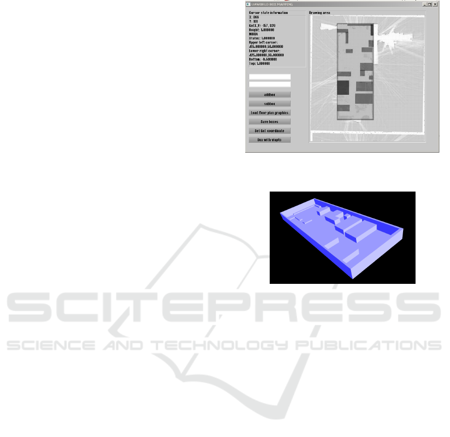
4.1 Graphical User Interface
A proof of concept GUI, based on the Irrlight open
source 3D engine (Gebhardt, 2016), has been imple-
mented. The first action performed by the user is to
load floor map graphics, which is then shown as a
background in the map design area as shown in fig-
ure 2 (a).
Exterior wall boundaries are then added as an
APB by pointing mouse to upper left and lower right
corners of the boundary. Vertical coordinates are pro-
vided through mouse wheel. Next, interior bound-
aries are given as an APB and subtracted to create
surrounding walls.
In the following mapping process the user will
provide APBs for each box shaped obstacle inside
the room and if necessary provide several APBs for
obstacles far from box shape. An impression of the
mapping process if shown in figure 2(a) with a 3D
visualization in figure 2(b)
5 PATH PLANNING
A number of path planning approaches exist; such
as gradient following with artificial potential fields
(Horner and Healey, 2004), navigation functions cre-
ated through the solution of the stationary heat equa-
tion (Connolly et al., 1990), which bears close resem-
blance to solving the shortest path problem for all-
to-one location. Such approaches constitute feasible
path planning back-ends to the 3D boxmap presented
earlier. However, as described in (Scholer, 2012) any
3D shortest path in smooth environments is composed
of an alternate sequence of straight lines and obsta-
cle surface geodesics. We adopt this insight for path
planning along with the restriction that any obstacle
in a boxmap is indeed a polyhedron for which sur-
face geodesics appear as sequences of straight lines.
This in turn makes any path a connected sequence of
(a) 2D top view of interior obstacles included as Axes
Parallel Boxes in map design area of prototype design
application.
(b) 3D view of interior obstacles in-
cluded as Axes Parallel Boxes.
Figure 2.
straight lines. A similar approach is taken in (Lozano-
P
´
erez and Wesley, 1979) where obstacle avoidance
and path planning is investigated for general polygons
in the plane. From a computational point of view
(Canny and Reif, 1987) proved that the 3D shortest
path problem even for polyhedral obstacles is NP-
hard, which calls for further reductions in complex-
ity to allow scalability. Indeed in (Canny and Reif,
1987) the set of shortest paths are divided into classes
with equivalent edge sequences. Within each class the
shortest path problem is itself a non-convex real val-
ued optimization problem.
5.1 Generation of Via Points
In the following we pursue the approach of (Lozano-
P
´
erez and Wesley, 1979) in 3D, where the topology
of the environment is given with a discrete set of via
points as well as the visibility graph connecting them.
At this point the question arises on how to identify
a suitable set of via points. On the one hand the set
of via points has to be sufficiently dense to allow a
proper approximations of shortest paths and on the
other hand to be of sufficiently low cardinality to not
jeopardize scalability. Due to the real valued nature
Easy 3D Mapping for Indoor Navigation of Micro UAVs
303
of the problem, infinite density of via points on obsta-
cle edges is needed to obtain optimality. We provide a
user specified density on box edges to allow the user
to make the tradeoff between precision and complex-
ity. As opposed to the grid approach adopted by (Lin
et al., 2013) defining via point to the open space, we
confine via points to be associated only to obstacles.
The reason for that is two-fold; since shortest paths
are straight lines through open space, no via points
are needed there and secondly the grid approach in
(Lin et al., 2013) scales badly in higher dimensions.
Although precision is left as a design issue for
the user, it seems valuable that our tool provides
some assistance in avoiding infeasible via point sets.
We say that a set of via points V ⊂ F is feasible
if, for each pair of mutually reachable points in the
map, there is a path through via points. More pre-
cisely, if o ∈ R
3
and d ∈ R
3
are mutually reachable,
then a subset {v
1
, .., v
m
} ⊆ V exists so that the point
pairs {(o, v
1
), (v
1
, v
2
), .., (v
m−1
, v
m
), (v
m
, d)} are mu-
tually visible. We say that points o and d are mutually
reachable on V .
Feasibility of a set of via points V is ensured if
all points in V are mutually reachable on V and for
every point o ∈ F, ∃v ∈ V such that o and v are mutu-
ally visible. Within computational geometry the prob-
lem of placing via points (guards) to make all other
points visible from at least one via point, is equivalent
to the so called Fortress Problem (O’Rourke, 1987),
which has been predominantly treated in two dimen-
sions, i.e. for polygons and in close connection with
the related Art Gallery Problem. In (Viglietta, 2012)
a 3D example (the octoplex) is given, where the Art
Gallery Problem is unsolvable with via points con-
fined to the vertices (corners) of the polyhedron. Sim-
ilar to boxmap obstacles the octoplex is an orthogo-
nal polyhedron. Since the 2D Fortress Problem can
be reduced to the 2D Art Gallery Problem, it seems
nearby to conjecture the 3D Fortress Problem unsolv-
able for via points confined to vertices. However the
octoplex and its generalizations (multiplexes) are all
externally visible from vertices, i.e. the Fortress Prob-
lem is solvable with via points confined to vertices for
multiplexes.
For a boxmap comprising only non-overlapping
APBs this is directly accomplished by assigning via
points to all 8 corners of every APB. If some APBs are
overlapping, the situation is more complicated. Over-
lapping APBs are handled through the definition of
almost disjoint box subtraction. When an APB B is
added to a boxmap M we shall instead of (3) apply
the almost disjoint box addition in (17), i.e.
M
0
= M +
d
B = M +B + (M −
d
B) + (B −
d
M) (17)
which by definition is commutative. It is readily veri-
fied by inspection that
|M + B| = |M +
d
B| = |M| ∪ |B|
Next, if M includes a set of almost disjoint APBs {B
i
}
so that |M| = | ∪
i
{B
i
}| then M
0
includes a set of al-
most disjoint APBs {B
0
i
} so that |M
0
| = | ∪
i
{B
0
i
}|. We
say that M and M
0
both have an almost disjoint rep-
resentation. Thus, if a boxmap is constructed through
consecutive applications of almost disjoint additions
and subtractions, it contains at all times a set almost
disjoint APBs occupying the same space. Every cor-
ner of these APBs will be assigned a via point leading
to the result, that at least every vertex of the boxmap
is equipped with a via point.
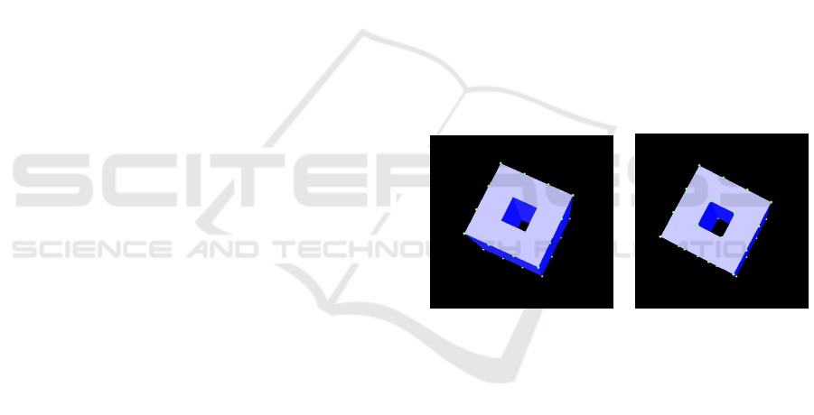
Consider the following map M
M = {(0, 1, 0, 3, 0, 4),
(2, 3, 0, 3, 0, 4),
(0, 3, 0, 1, 0, 4),
(0, 3, 2, 3, 0, 4)}
Assume each APB B
i
in M is added according to (3)
and equipped with via points at its corners. Then
only the outside of the tunnel shown in figure 3(a)
is equipped with via points, leaving the inside of the
tunnel invisible.
(c) Tunnel with exterior via
points and invisible posi-
tions inside
(d) Tunnel with via points
on inner edges and visible
positions inside
Figure 3.
If on the other hand each APB B
i
in M is added
according to (17) via points are also assigned to the
inner corners of the tunnel, rendering the inside of the
tunnel visible as shown in figure 3(b).
5.2 Feasibility Proposition and
Statistical Proof
We conjecture the feasibility of the presented method,
i.e. boxmaps constructed through consecutive appli-
cations of (17) and via points are assigned to all cor-
ners of all APB’s in the map. The restriction to almost
disjoint box addition (17) represents no loss of gen-
erality, since every boxmap M = {B
i
} can be recom-
puted recursively through (17) yielding the desired re-
sult.
ICINCO 2017 - 14th International Conference on Informatics in Control, Automation and Robotics
304

Some effort has been put into the formal proof
of the presented proposition without success. Thus,
in the absence of formal proof a statistical proof has
been devised as presented below.
• for i=1:N
– Generate random path P connecting end points
O and D
– Generate random boxmap M = {B
1
, .., B
L
} not
intersecting P
(through consequtive applications of almost
disjoint addition)
– Assign viapoints {v
p
} to all corners of all APBs
in M
– Compute visibility graph G for {O, D, {v
p
}}
and M
– Compute path P
0
= O, v
k
1
, .., v
k
n
, D in G
The origin O = (0, 0, 0) is fixed through all iterations
1, .., N. For each iteration the random path is specified
through a sequence of points O = p
1
, .., p
Q+1
= D de-
fined as a random walk. The boxmap M = B
1
, .., B
K
is generated through an accept/reject strategy. The
accept/reject strategy discards boxes intersecting line
segments (p
i+1
, p
i
) such that a path connecting O and
D is guaranteed by design. The procedure continues
until the specified number L of APBs are accepted.
One representative sample is shown in figure (4).
Figure 4: Randomly generated path, boxmap and path
through via points. Random path P is shown as red lines,
the path through via points P
0
shown in white lines and com-
plete set of via points shown as red boxes.
For every iteration the non-existence of the path
P
0
constitutes a counter example for the presented
proposition regarding the feasibility of via point
assignment. So far P
0
has existed for N = 50.000
consecutive iterations with Q = 10 and K = 20.
5.3 Flight Altitude Levels
Additionally a finite number of preferred altitude
flight levels L = {l
1
, .., l
N
} are defined. For each
APB we define path via points on the intersection be-
tween the APB surface and each flight level, i.e. for
B = (x
1
, x
2
, y
1
, y
2
, z
1
, z
2
) we define B
∞
by
B
∞
= (x
1
, x
2
, y
1
, y
2
, −∞, ∞) (18)
vp ∈ B
∞
∩ {(x, y, z)|z ∈ L} (19)
where vp is a via point. To allow for vertical climb
and descent, we provide additional via points by us-
ing (in (19)) an extension B
∞
of the APB extended
vertically to cover all flight levels. On the intersec-
tion via points are defined at least on edges but may
be set by a maximum distance to encircle the APB in
each flight level. A 3D impression of an APB with via
points in 3 flight levels is shown in figure 5
Figure 5: APB (0,10,0,10,0,10) with via points defined for
flight levels (7,9,12) at a distance 2.
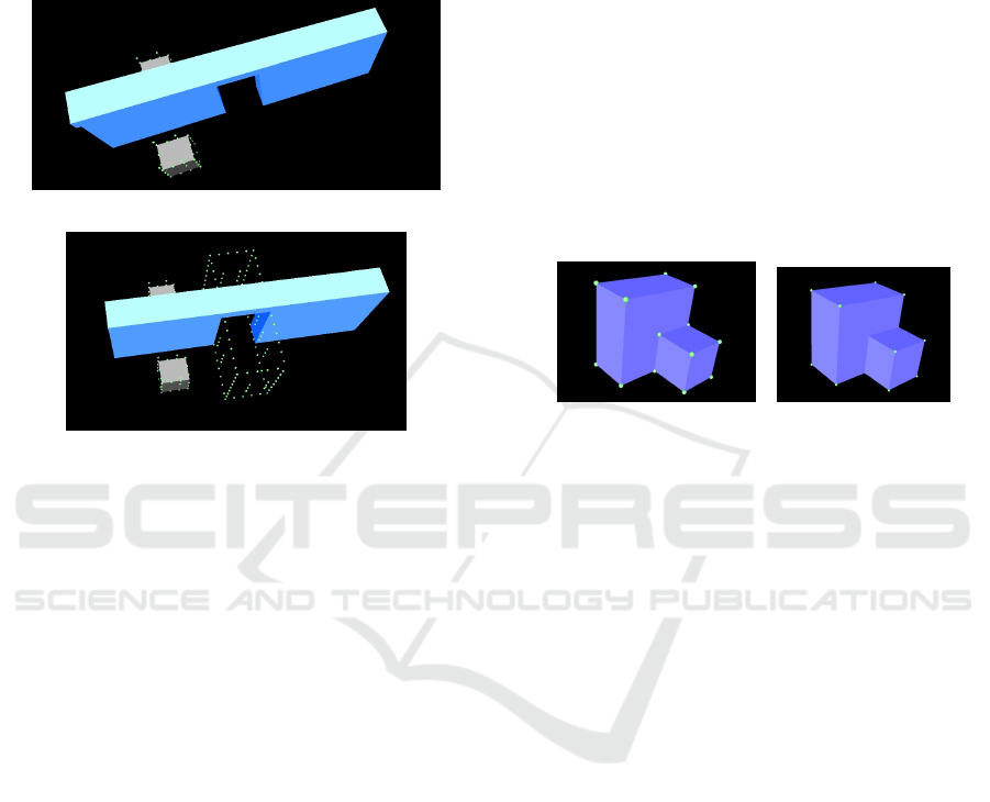
5.4 Reduction of Via Points
As such any obstacle in a boxmap generates its own
via points necessary for avoiding it. Some APBs can
however appropriately be excluded from generating
via points; namely walls without openings as well as
floors and ceilings. A 3D image illustrating a boxmap
with via points only on inner obstacles is shown in
figure 6.
Figure 6: Boxmap with via points only on obstacles and
flight path.
Excluding part of the boxmap from generating via
points provides a welcomed opportunity for reducing
Easy 3D Mapping for Indoor Navigation of Micro UAVs
305
the complexity of the map and in turn supporting scal-
ability. However, it may on the other hand jeopar-
dize feasibility. Consider the case where two rooms
are connected by wall opening (door/window) and the
wall does not itself generate via point. Such a situa-
tion is depicted in figure 6(a).
(a) Infeasible via point set for separating wall.
(b) Feasible via point set for separating
wall.
Figure 6.
To counteract this problem, we provide the op-
portunity to let subtracted boxes such as wall open-
ings generate via points. The example from 6 can be
remedied by allowing the door opening to generate
via points as shown in figure 6(b).
6 OBSTACLE DILATION
The exposition so far, considered neither the physical
dimensions of the vehicle itself nor the need for safety
zones around physical obstacles. Both concerns are
met through the definition of δ -padding of APBs ,
i.e. for B = (x
1
, x
2
, y
1
, y
2
, z
1
, z
2
)
·
δ
: B → B
B
δ
=
(x
1
− δ, x
2
+ δ, y
1
− δ, y
2
+ δ, z
1
− δ, z
2
+ δ)
(20)
δ-padding, as presented, is a rather crude approach
to dilation, which in fact presumes cubic physical di-
mensions (2δ, 2δ, 2δ) of the vehicle. It is however
straight forward to extend the definition to vector val-
ued δ, presuming vehicle dimensions (2δ
x
, 2δ
y
, 2δ
z
).
This however does not directly take into account at-
titude changes of the vehicle. We assume attitude
changes are predominantly around the z-axis (yaw)
and set δ = (max {δ
x
, δ
y
}, max{δ
x
, δ
y
}, δ
z
).
δ-padding needs to be considered in relation to fea-
sibility of via points. With the definition of almost
disjoint box operations given above, we may assume
that all obstacles have almost disjoint representations.
Without δ-padding paths exist between APBs with
overlapping faces. Consider an example where M =
A + B and
A = (0, 1, 0, 1, 0, 1)
B = (1, 2, 0, 2, 0, 2)
with via points on box corners as illustrated in figure
7(a)
(c) Boxmap without δ-
padding.
(d) Boxmap with
δ-padding on every
APB.
Figure 7.
Without δ-padding via points v
1
= (1, 1, 1) and
v
2
= (1, 0, 0) would be mutually visible even though
there is no room between A and B. On the other hand,
with δ-padding v
δ
1
= (1 + δ, 1 + δ, 1 + δ) belongs to
the interior of |B
δ
|, which in turn jeopardizes the fea-
sibility of via point assignment as illustrated in figure
7(b).
We introduce the almost disjoint summation
d
∑
re-
cursively, i.e. for M = {B
1
, .., B
N
} and Γ : B → B
M
1
= Γ(B
1
)
M
i
= M
i−1
+
d
Γ(B
i
)
d
∑
B
i
∈M
Γ(B
i
) = M
N
(21)
With the definition of almost disjoint summation we
may extend the definition of δ-padding to boxmaps.
We define almost disjoint δ-padding ·
δ
: for boxmaps
by
·
δ
: M → M
M
δ
=
d
∑
B
i
∈M
B
δ
i
(22)
The example boxmap with almost disjoint δ-padding
is shown in figure 8. Since the almost disjoint δ-
padded boxmap in figure 8 includes both A
δ
and B
δ
no paths exist in between the touching faces of APBs
ICINCO 2017 - 14th International Conference on Informatics in Control, Automation and Robotics
306

Figure 8: Boxmap with almost disjoint δ-padding.
A and B. On the other hand, it also includes both
A
δ
−
d
B
δ
and B
δ
−
d
A
δ
, which ensures via points on
all corners of |M|.
7 COMPLEXITY
CONSIDERATIONS
The suggested method generates complexities in dif-
ferent stages. Assume a boxmap M = {B
1
, .., B
M
} is
defined by the user through the graphical user inter-
face. For via point assignment an almost disjoint rep-
resentation {A
1
, .., A
L
} needs to be computed, where
potentially L >> M. The complementary (B
0
i
)
c
of
any APB B
0
i
has a finite almost disjoint representa-
tion {B
1
i
, .., B
6
i
}. Now consider intersections such as
C = ∩
j=1..M
|B
k
j
j
|, then an APB A exists such that
|A| = C. Denote by C the set of such APBs. There
are at most 8
M
such intersections, which are all dis-
joint and constitute a partition of R
3
. For any APB B
i
in M we have
|B
i
| = ∪
p=0..7
∩
j<i
|B
k
j
j
| ∩ |B
p
i
| ∩
j>i
|B
k
j
j
| (23)
Thus, an almost disjoint representation entirely in
C of M exists. Since #C = 8
M
, we have L ≤ 8
M
.
This number is however extremely large compared
to realistic situations. For the M-tech lab case intro-
duced above we have M = 22 and L = 44, whereas
8
M
= 7.4E19.
We assign via points to all corners of APBs in the
disjoint representation {A
1
, .., A
L
} as well as all edges
and flight levels of APBs in {B
1
, .., B
M
} with some
distance δ. This amounts to V = 8L + 12Md
D
B
δ
e +
ML
f
4
D
B
δ
via points, where D
B
is an upper bound on
APB dimension and L
f
is the number of predefined
flight levels. For the M-tech lab case we set D
B
= 10,
δ = 0.5 and L
f
= 3 which amounts to V = 10912.
The M-tech lab covers 40 × 14 × 9 m
3
such that cov-
ering it with via points in a regular grid of distance δ
amounts to 37169 via points (in open space). How-
ever the bounds applied are overly pessimistic as re-
sults from mapping the M-tech lab demonstrates. Af-
ter pruning away corners entirely in the interior of
APBs, we get 336 via points on APB corners, 1164
via points on APB edges and finally 1230 for 3 flight
levels amounting to 2730 via points. Creating the vis-
ibility graph is linear in the product V
2
× M or in this
case 2730
2
∗ 22 = 163.963.800. This can be done in
400 seconds on an Intel Quad Core Atom processor
running 1.33 Ghz. Although significant, the compu-
tation of the visibility graph is a one time endeavor,
whereas including a new origin-destination pair in the
visibility graph is done in 59ms. We assume comput-
ing the visibility graph for regular grids is of lower
complexity due to simple neighbor relationships and
may be done during path finding. Path finding either
by the Dijkstra- (Dijkstra, 1959) or the A
∗
-algorithm
(Hart et al., 1968) is known to scale quadratically with
the size of the graph. Since we have not implemented
path finding for regular grids we compare the above
numbers, i.e. 37169 via points for a regular grid and
2730 for the proposed method. Applying a quadratic
scale we obtain a complexity advantage of the pro-
posed method over regular grids of approximately 185
times. A number of paths in the visibility graph for
the M-tech map are conducted with execution times
around 100ms.
8 CONCLUSION
The paper presents an approach to easy (user-
friendly) 3D mapping of interior environments for in-
door UAV operations. The basic mapping element
is the Axes Parallel Box (APB) for which algebraic
operations are defined and made applicable to the
user to allow both additive mapping, where obstacles
are added consecutively to the map and subtractive,
where openings such as doors and windows can be
inserted. A SW application is developed, providing
a Graphical User Interface allowing the user to con-
struct a 3D map based on available 2D floor maps.
Floor maps may appear either in the shape of an ar-
chitectural blue print or, as exemplified in the paper,
a ROS map acquired through LIDAR measurements
from an UGV. A framework for topological mapping
is presented, where a finite set of via points is de-
fined, such that every flight path is defined as a se-
quence of via points. A minimal requirement feasibil-
ity is defined as the guarantee, that for every mutually
reachable pair of via points there is a path through via
points. A procedure to guarantee feasibility is pre-
sented along with a statistical proof of the correctness
of the procedure.
Possible extensions are discussed for interiors
with a major presence of non axes-parallel structural
elements. It is suggested to confine such extensions
to be overall additive to maintain a reduced complex-
Easy 3D Mapping for Indoor Navigation of Micro UAVs
307

ity. Complexity is considered in comparison with a
regular grid approach and for a benchmark example.
Results point unambiguously in favor of the proposed
procedure. A procedure for aligning map coordinates
with the coordinates of an indoor positioning systems
is implemented in the developed SW application but
left out of this presentation for brevity.
We find the presented methodology to be a useful
candidate approach for user-friendly 3D mapping of
UAV flight spaces both as a stand-alone tool, but also
in combination with e.g. SLAM based solutions. One
could foresee our solution to define the initial map
to be subsequently refined over time with informa-
tion from a SLAM procedure. Such approaches along
with the presented extension possibilities of the map-
ping procedure outline directions for future research.
This along with formal proofs of conjectured feasi-
bility results which are only supported by convincing
statistical evidence in this paper. Formal feasibility
proofs would indeed be an indpendent result within
computational geometry.
REFERENCES
(2017). SketchUp. https://www.sketchup.com/. [Online;
accessed 28-February-2017].
Boniardi, F., Valada, A., Burgard, W., and Tipaldi, G. D.
(2016). Autonomous indoor robot navigation using
a sketch interface for drawing maps and routes. In
2016 IEEE International Conference on Robotics and
Automation (ICRA), pages 2896–2901.
Canny, J. and Reif, J. (1987). New lower bound techniques
for robot motion planning problems. pages 49–60.
Connolly, C. I., Burns, J. B., and Weiss, R. (1990). Path
planning using laplace’s equation. In In Proceed-
ings of the 1990 IEEE International Conference on
Robotics and Automation, pages 2102–2106.
de Velde, S. V. (2016). Pozyx-Accurate positioning.
https://www.pozyx.io/. [Online; accessed 08-July-
2016].
Dijkstra, E. W. (1959). A note on two problems in connex-
ion with graphs. Numer. Math., 1(1):269–271.
Edirisinghe, R. and London, K. (2015). Comparative anal-
ysis of international and national level bim standard-
ization efforts and bim adoption. In Proceedings of
the 32nd International Conference of CIB W78, CIB
W78, pages 149–158.
Gebhardt, N. (2016). Welcome to the Irrlicht Engine.
http://irrlicht.sourceforge.net/. [Online; accessed 08-
July-2016].
Hart, P. E., Nilsson, N. J., and Raphael, B. (1968). A formal
basis for the heuristic determination of minimum cost
paths. IEEE Transactions on Systems, Science, and
Cybernetics, SSC-4(2):100–107.
Horner, D. P. and Healey, A. J. (2004). Use of artificial
potential fields for uav guidance and optimization of
wlan communications. In Autonomous Underwater
Vehicles, 2004 IEEE/OES, pages 88–95.
Lin, Y.-H., Liu, Y.-S., Gao, G., Han, X.-G., Lai, C.-Y.,
and Gu, M. (2013). The ifc-based path planning for
3d indoor spaces. Advanced Engineering Informatics,
27(2):189 – 205.
Lozano-P
´
erez, T. and Wesley, M. A. (1979). An algo-
rithm for planning collision-free paths among polyhe-
dral obstacles. Commun. ACM, 22(10):560–570.
Mart
´
ınez, C., Mondrag
´
on, I. F., Campoy, P., S
´
anchez-
L
´
opez, J. L., and Olivares-M
´
endez, M. A. (2013).
A hierarchical tracking strategy for vision-based ap-
plications on-board uavs. Journal of Intelligent &
Robotic Systems, 72(3):517–539.
O’Rourke, J. (1987). Art Gallery Theorems and Algorithms.
Oxford University Press, Inc., New York, NY, USA.
Scholer, F. (2012). 3D Path Planning for Autonomous
Aerial Vehicles in Constrained Spaces. PhD thesis.
Theilgaard, N. B. (2016). Model Railroad without wires.
http://www.gamesontrack.dk/. [Online; accessed 08-
July-2016].
Viglietta, G. (2012). Guarding and searching polyhedra.
CoRR, abs/1211.2483.
Voelcker, H. B. and Requicha, A. A. G. (1977). Geometric
modeling of mechanical parts and processes. Com-
puter, 10(12):48–57.
Yuan, W. and Schneider, M. (2011). 3D Indoor Route
Planning for Arbitrary-Shape Objects, pages 120–
131. Springer Berlin Heidelberg, Berlin, Heidelberg.
ICINCO 2017 - 14th International Conference on Informatics in Control, Automation and Robotics
308
