
Formal Verification for Validation of PSEEL’s PLC Program
Mohamed Niang
1,2
, Alexandre Philippot
1
, François Gellot
1
, Raphaël Coupat
2
, Bernard Riera
1
and Sébastien Lefebvre
2
1
CReSTIC (EA3804), University of Reims Champagne Ardenne Moulin de la Housse,
BP 1039, 51687 Reims CEDEX 2, France
2
IP.TE (CES), Direction de l’ingénierie, Société Nationale des Chemins de fer Français,
6 avenue François Mitterrand – 93574 La plaine Saint Denis CEDEX, France
Keywords: Model-checking, Recipe Book, Factory Tests, Systems Engineers, Railways, Safety.
Abstract: In order to keep its leadership in French rail market and to improve work conditions of its systems engineers
during automation projects, the SNCF (French acronym for National Society of French Railways) wants to
develop solutions increasing the productivity. One of these improvements focuses on the current
methodology used by systems engineers to verify and validate PLC programs of electrical installations. This
task remains one of the most important during an automation project because it is supposed to ensure
installations safety, but it must be optimized. Through an industrial thesis financed by SNCF, the aim of this
research project is to improve this method and reduce time validation of programs by providing a tool which
will help systems engineers to verify and validate quickly and automatically PLC programs during any
automation project, not necessarily during factory tests but directly from their office.
1 INTRODUCTION
In automated systems, most of accidents that occur
in industry have been discovered to be the result of
Programming errors (Mokadem et al., 2010).
Therefore, verification of PLC program before its
implementation remains a very important task
during an automation project. This verification must
concern both functional and safety parts. The first
one ensures that the PLC programs meet the
functional specifications, and the second one
consists in verifying if the controlled system can be
or not exposed to dangerous states leading to human
and equipment damage. Nowadays, some
verification and validation techniques like tests and
simulation are available.
At SNCF, the system engineers apply currently
these methods to validate the control command
(programs and electrical cabinets’ wiring) of PSEEL
(Power Supply Equipment of the Electric Lines) by
using a recipe book which contains a set of scenarios
or sequential instructions. According to their know-
how and experience during these last decades about
their systems, they consider that a PSEEL’s control
command is valid once it satisfies the whole test.
The verification consists in executing manually each
instruction contained in the recipe book during
factory tests, and then comparing the obtained
results with the expected ones. This verification is
therefore not automatic, and requires too much time
because of the length of tests (almost 100 pages of
instructions). Moreover, although it was used to
validate PLC programs for several decades, this
method is not efficient to check formally safety part
of PLC programs insofar as it verifies only if PLC
programs meet the requirements specifications.
Our first task in this work is to optimize this
current methodology of verification by making it
faster and automatic with the use of a model-
checker. Then we propose an exhaustive method
which will be used to verify the safety part of PLC
programs.
After a presentation of general context in section
2, we detail the principle of our methodology and
illustrate it through an application in section 3.
Exhaustiveness of recipe book is studied in section
4, and section 5 introduces a solution for automatic
generation of models used for programs verification.
We conclude finally this paper and propose some
work prospects in section 6.
Niang, M., Philippot, A., Gellot, F., Coupat, R., Riera, B. and Lefebvre, S.
Formal Verification for Validation of PSEEL’s PLC Program.
DOI: 10.5220/0006418705670574
In Proceedings of the 14th International Conference on Informatics in Control, Automation and Robotics (ICINCO 2017) - Volume 1, pages 567-574
ISBN: 978-989-758-263-9
Copyright © 2017 by SCITEPRESS – Science and Technology Publications, Lda. All rights reserved
567
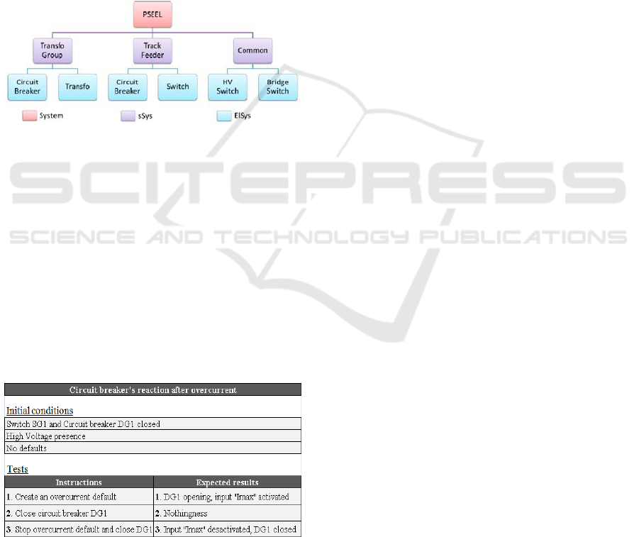
2 GENERAL CONTEXT
The PSEEL are the electrical supply points of the
electrified lines, called catenaries. Their role is to
transform, to supply, and to rectifier in the case of
DC supply, the tension of the High-Voltage (HV)
network into compatible tension with traction units
(1500 V DC or 25kV AC). They are composed of
sub-systems (sSys) like Transformer Group, Track
feeder, and common, and each of these sub-systems
is composed of elements of sub-Systems (ElSys) like
switch, circuit breaker, and so on (Figure 1). These
electrical systems are subject to strict standards of
railway safety (EN 50126, 2012) (IEC 60870-4,
2013).
Figure 1: Decomposition of PSEEL.
The PSEEL are distributed automated systems
whose control command can be done either locally
or remotely in a centralized control station named
Central Sub-Stations (CSS).
The recipe book represents for SNCF the main
reference for validation of PSEEL’s control
command systems since many years. It contains
several scenarios that systems engineers execute on
PSEEL and analyze its behavior in order to validate
or not its control command. An example of a test
scenario is presented in Table 1.
Table 1: Example of one test scenario in recipe book.
During an automation project, the recipe book
and the PLC programs are automatically generated
with software named Odil (Coupat, 2014). For this,
the systems engineers enter all inputs data of the
system (like single line diagram of PSEEL,
equipment configuration, inputs/outputs ...) and
then, Odil generates automatically programs and
recipe book. After a proofreading of these latter,
they verify online the correctness of whole control
command (PLC program and electrical cabinets)
during factory tests, by executing all the scenarios of
the recipe book on system. Moreover during factory
tests, they need to connect devices simulators to
cabinets (like switches and circuit breakers) in order
to make tests possible. One major difficulty they can
encounter during tests is that in case of an
unsatisfied instruction in factory, they must analyze
the problem and determine its cause (programming
error or wiring error of electrical cabinets). For
example in the test scenario described in Table 1,
when the circuit breaker does not open after
overcurrent (instruction N°1), there are two possible
explanations:
o The information “Imax” is not received by the
PLC (because the input is not wired for
example);
o The information is received but the SFC program
of the circuit breaker does not evolve (bad
program).
Despite their experience, this diagnosis may remain
long and complex in some cases. The main approach
of our methodology consists in dividing the
validation
step into two parts: offline validation of
PLC programs with model-checker Uppaal
(Behrmann et al., 2002), and then online validation
of electrical cabinets during factory tests with virtual
commissioning. Thus, PLC programs can be
validated earlier with Uppaal and before factory
tests. Moreover, this validation step does not require
physical devices simulators because they are now
included in Uppaal models. From a model of
PSEEL, PLC programs, and recipe book, Uppaal is
able to check automatically during the simulation if
the PLC programs satisfy the recipe book. For this,
the model-checker executes all scenarios of recipe
book on the system, and verifies if there exists at
least one instruction in the recipe book whose effect
on the PSEEL does not correspond to the expected
one. Then, simulation results will help to diagnose
easily the problem if it exists, or otherwise to
validate the PLC programs. The validation of
electrical cabinets will be done online and also
automatically, with the use of virtual commissioning
connected to electrical cabinets (not presented in this
paper). The advantage of this methodology is as
follows: not only the validation of programs will be
faster and automatic, but it will also facilitate the
validation of electrical cabinets. In fact, once we
implement valid PLC programs in the system, any
ICINCO 2017 - 14th International Conference on Informatics in Control, Automation and Robotics
568
encountered problem during factory tests would
necessarily result from wiring errors of electrical
cabinets. Another objective in this work is to
propose with model-checking an exhaustive method
which verifies the safety part of PLC programs.
System modeling is the first step of our approach.
3 SYSTEM MODELING
In this section, we present and illustrate our
methodology through its application on a
transformer group (PSEEL’s sub-system). System
modeling requires careful structural analysis of
PSEEL and PLC programs because the models must
have the same behavior as real system. The
transformer group is controlled by one PLC, and is
basically composed of circuit breakers, switches,
and transformer. Its program’s outputs correspond to
the orders sent to devices, and inputs are the
observed faults on operative part and the devices’
states (opened or closed). The programs are
designed in STRATON (www.copalp.com) using
some of the standardized languages (IEC 61131-3,
2003) such as Ladder Diagram (LD), Sequential
Function Chart (SFC) and Structured Text (ST). But
in our Uppaal models, the whole program needs to
be translated into ST because the model-checker
cannot interpret the other languages. Whatever the
programming language would be, each scan cycle
includes three main phases: input reading, program
execution and output updating.
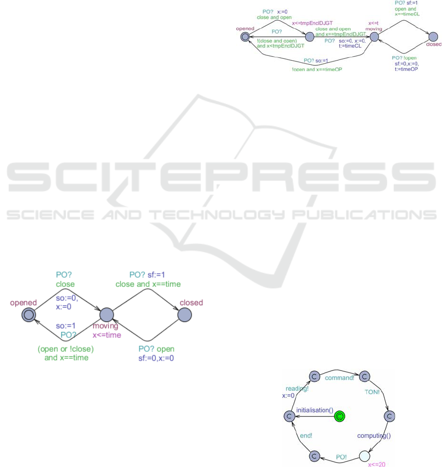
3.1 Transformer Group Modeling
Figure 2: UPPAAL model of switch.
The variables “so” and “sf” (Figure 2) represent
respectively the information “switch opened” and
“switch closed”, and “close” (respectively “open”)
represents closing order (respectively opening order)
sent by the programs. The switch can reach three
possible states: opened (so=true and sf=false),
moving (so=false and sf=false), and closed
(so=false and sf=true). Initially opened, it starts
moving once it receives closing order from the
program. Then, after a certain duration (x==time) it
becomes fully closed if the order was still
maintained, or otherwise returns to the initial state if
closing order was released or if opening order was
activated. The switch’s behaviour is practically the
same when it receives opening order from closed
state. We recall here that the order sent by operator
is not directly received by the device, but rather by
its SFC program which will apply it or not, if the
program allows this action.
Figure 3: UPPAAL model of circuit breaker.
The model of a circuit breaker presented in
Figure 3 has some particularities compared to switch
model:
o To close the circuit breaker, the two orders (open
and close) must be maintained simultaneously
for a certain duration (x==tmpEnclDJGT);
o To open it, just release the opening order;
o Contrary to the switch, opening time (timeOP) is
different from closing time (timeCL).
Note that although the transformer has continuous
behaviour (magnetic, thermal…), we do not take it
into account in its model. So we represent it as a
structure of variables (observers, parameters, and
observed faults) because these are the only
information we need for this model:
struct {bool defBLQ, blocDef, defTemp, defBLQR,
blocDefRed, defTempRed, wdMicom, TcMC,
temp2TR, AMR, fuFuRC, AvDiode, imaxGT,
OoAbsUHT, OoDjAbsUHT, deblocGT, absUBarre,
presenceSGT, pres_Hexa; int tmpReencGT;} GT1;
3.2 Control Program Modeling
Figure 4: UPPAAL model of PLC cycle.
Formal Verification for Validation of PSEEL’s PLC Program
569
The model in Figure 4 synchronizes all the other
models of the system thanks to broadcast channels.
PLC cycle structured as a loop includes a clock x
which measures the cycle time (equal to 20 time
units here). Initialisation of SFC programs and
parameters is required during the first PLC cycle.
Then, the cycle is composed of 6 steps:
o Input reading (faults and devices’ states)
o Command reading (sent by operators)
o Timers evolution (synchronised with TON!
channel)
o Execution of main program (SFC programs
update) followed by output writing;
o Evolution of operative part (channel PO!)
o End of cycle (channel end!)
To reduce states space, most of states are declared as
committed so that time can elapse only during
program execution. Therefore the duration of input
acquisition and output emission is negligible.
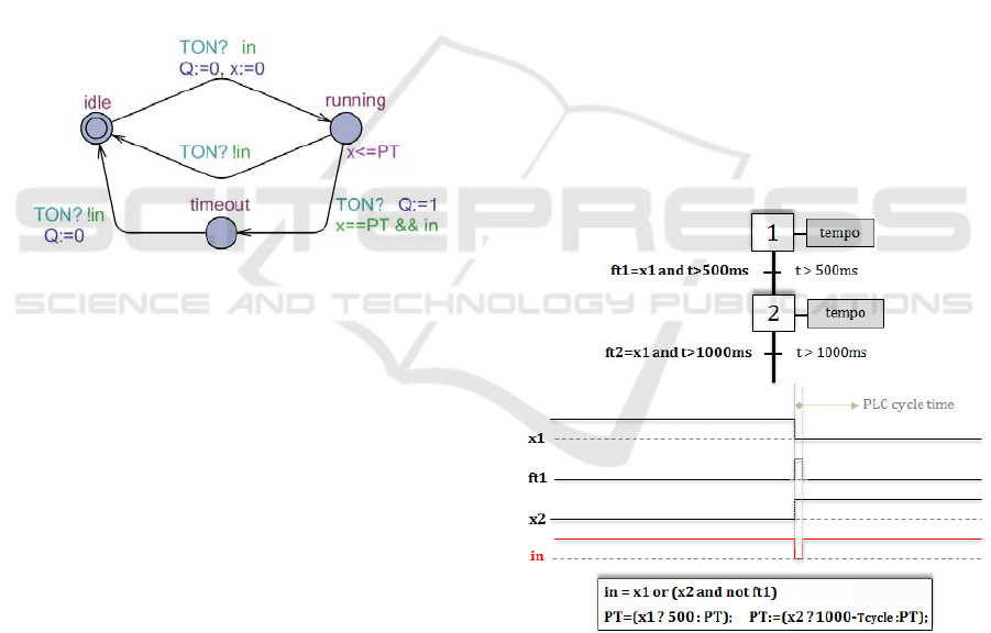
Figure 5: UPPAAL model of a TON block.
The control program contains timing operations,
described by functional blocks called TON (Timer
On-delay). Its behaviour is explained in IEC 61131-
3 standard. This TON block has two input variables
(boolean variable in to start or stop counting time,
and time parameter PT which indicates the timing
delay) and two output variables (boolean variable Q
which equals 1 if the delay has expired, and time
variable x which gives the time elapsed from the last
rising edge of in). Initially idle, its location becomes
running when the timer has been switched on, and
timeout when the fixed delay (PT) has been
reached. The model in Figure 5 has been inspired in
(Mokadem et al., 2010).
Any SFC program can use more than two TON
block in its different steps. So instead of using a
TON block for any step, we declare only one TON
block per SFC program. In fact, after a structural
analysis of these SFC programs, we noticed that we
can never have more than one step simultaneously
activated. Thus, a single TON block can be used by
all steps of one SFC program without any conflict.
However, for two successive steps using the same
TON, we must make sure that between the two
steps’ activation, the TON’s output changes from 1
to 0. For this, we must define correctly the inputs in
and PT of the TON block used by the SFC program.
In the example described in Figure 6, both steps x1
and x2 use the same TON. When x1 is activated,
time starts elapsing until it reaches 500ms. Then,
output Q and transition ft1 change from 0 to 1,
leading to x2’s activation and x1’s deactivation.
Therefore, the input in (whose expression is shown
in Figure 6) moves from 1 to 0 and resets the timer
(thus output Q changes from 1 to 0 and input PT
changes from 500ms to 1000ms). During the next
PLC cycle, the value of ft1 will be updated because
the step x1 is no more activated, so the input in will
move again from 0 to 1 and time will start again
elapsing for x2. But with these operations, we
noticed a delay of one PLC scan time from x2’s
activation to timer’s restart. To compensate this
delay, we subtract it to the pre-set time of x2. This
optimization will reduce the number of TON used,
and consequently the space of reachable states.
The whole program is not represented in our
model because some lines of code are only dedicated
to send information to other PLC through network
(Factory Instrumentation Protocol).
Figure 6: Example of TON’s use in a SFC program.
So the control program is basically composed of:
o SFC block programs: which command the
equipment like switches and circuits breakers.
The structure of the SFC program depends on the
kind of equipment.
o LD programs: where devices’ states are read and
all observed faults are collected and used to
compute observers.
ICINCO 2017 - 14th International Conference on Informatics in Control, Automation and Robotics
570
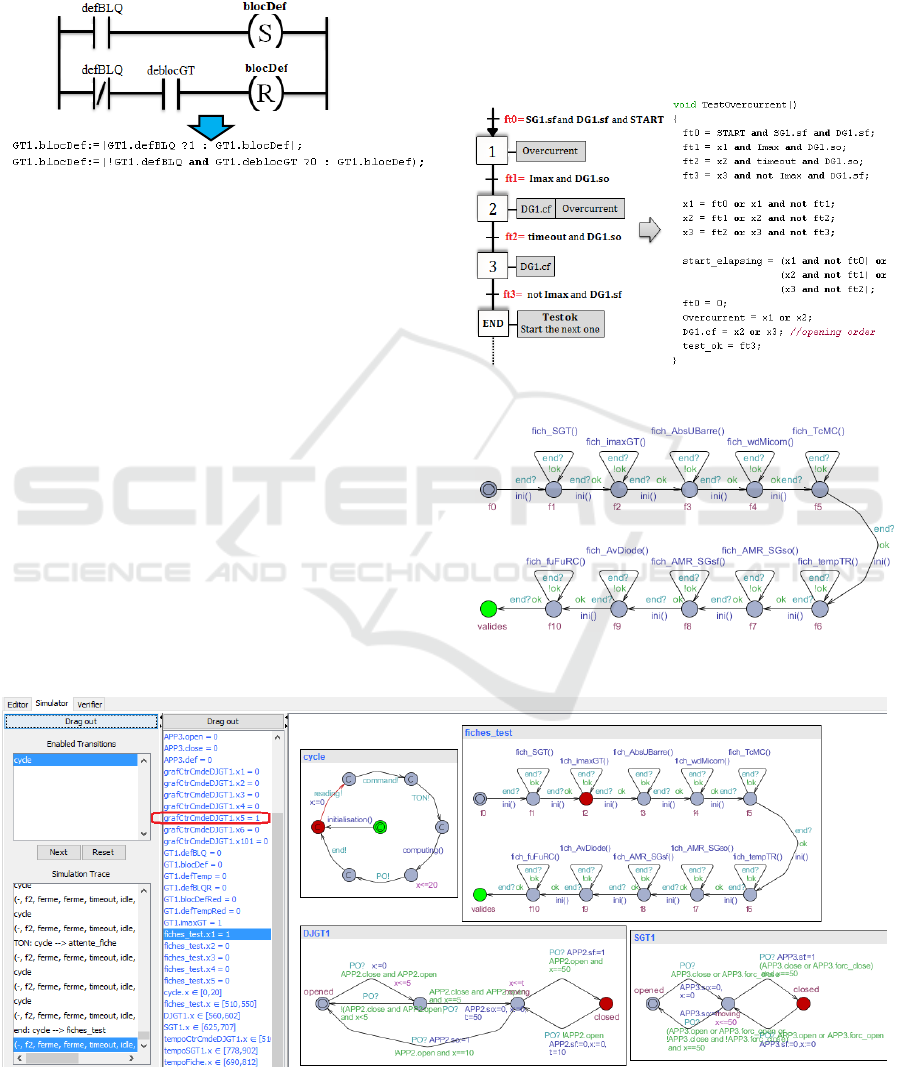
The SFC programs will be translated into Structured
Text language (ST), using the classical algebraic
representation of SFC (Machado et al., 2006). The
LD programs will also be translated into ST
language (Figure 7).
Figure 7: Example of LD programs translation into ST.
3.3 Recipe Book Modeling
After a structural analysis of recipe book, we
realized that it could be translated into SFC
programs (one per scenario) because it is composed
of actions and transitions. In Figure 8 we present the
translation of scenario described in Table 1. The
variable “start elapsing” is dedicated to trigger a
timer which counts the elapsed time in one step of
the scenario (x1, x2, or x3 in this example). So if
there is a step on which the elapsed time exceeds a
certain value (which is not supposed to be reached if
the program is valid), it will mean that program
presents errors because the transition associated to
that step cannot be satisfied.
This translation will be applied for all scenarios
of transformer group’s recipe book.
Then, the model described in Figure 9 will call
and execute sequentially all scenarios. The recipe
book’s evolution state will be updated during any
PLC scan time. Each state automaton of this model
(except the initial and last ones) corresponds to one
scenario. During simulation, one scenario can be
executed only if the previous one (if it exists) was
satisfied. Therefore the program is valid only if the
final state automaton (named valides in Figure 9) is
reachable, or if it does not exist a blocking
instruction in recipe book.
Figure 8: Translation of scenario into SFC program.
Figure 9: Uppal model of recipe book.
Figure 10: Simulation view.
Formal Verification for Validation of PSEEL’s PLC Program
571

3.4 Simulation Results
To validate the PLC program, all scenarios must be
executed and satisfied during simulation. For this,
we can verify if the final state automaton is
reachable by using the query:
E <> recipe_book.valides (1)
However the model checker does not return any
trace if (1) is not satisfied. Thus (1) is only useful to
determine if programs are valid or not, but not
sufficient for diagnosis. So instead of this property,
we verify if there exists a blocking step of a scenario
where the corresponding condition is not satisfied by
using the query:
E<>time_step.timeout (2)
Time step is a timer which counts the elapsed time
for any step of the recipe book. If (2) is satisfied, the
model checker will return directly the scenario and
blocking step on which simulation stopped.
Moreover, by analysing the current state of
programs, it will help for diagnosis. After a first
simulation (see results in Table 2), we realized that
(1) is satisfied and (2) is not: this is far from being a
surprise because the program we used here has
already been validated during factory tests.
In the following example, we used a modified
program to verify if problems can be diagnosed
during simulation. Table 2 presents simulation
results, and gives the time and memory used for
verification (on a windows machine with 4Gb RAM,
Core i5).
Table 2: Simulation results.
As expected, (1) is not satisfied for the modified
program, but to diagnose the problem, it is not
sufficient. So when we verify by using (2), the
model-checker has shown that the instruction N°1 of
overcurrent test is blocking (step x1 of Figure 8)
because the circuit breaker did not open after
overcurrent. Moreover, when we analyse the current
state of circuit breaker SFC program in simulation
results (see in Figure 10), we notice that its
evolution stopped in that moment on a step where it
was waiting for opening order (step x5 of SFC
program grafCtrCmdeDJGT1 in variables column
of Figure 10). Thus, we conclude that the transition
following that step is not correct because it did not
take into account the overcurrent information. This
result was expected because the expression “or
Imax” was initially deleted from that transition.
After correction and second simulation, the
instruction N°2 of overcurrent test (transition ft2 of
Figure 8) is not satisfied because the circuit breaker
started closing when it received that order whereas it
should not. In fact, the circuit breaker must stay
opened while overcurrent does not disappear. This
result was also expected because the expression
“and not Imax” was also deleted from SFC
program’s transition. In that way, we can diagnose
quickly and correct the whole program by referring
to the expected results of recipe book, and
simulation does not require too much memory. Its
efficiency has already been validated with some
examples of wrong programs.
4 SAFETY PART VERIFICATION
Although recipe book has served to validate
PSEEL’s programs for many decades, it is not
sufficient to verify formally installations safety. In
fact, the previous method does not study all the
reachable states of system (meaning all the 2
Ne
possible states, with Ne = number PSEEL’s sensors
+ number of received orders). Moreover, it has also
been proved in (Coupat, 2014) with a specific
PSEEL, that there exists one scenario (with low
occurrence) not included in recipe book, but which
can expose that PSEEL in dangerous state, meaning
that the method is not exhaustive. So supposing that
events like sending orders by operator or faults
apparition can occur whenever on system, the
principle is to check with Uppaal if each of these
states is not dangerous (meaning does not violate a
set of safety properties). Therefore recipe book will
no more represent a reference of verification. We
delete its model and we add two others ones that
generate randomly faults (left side on Figure 11) and
sending order (right side of Figure 11). With the first
model, fault can take two possible boolean values
(true or false), and with the second one a device’s
SFC program can receive opening order from
operator (co=true and cf=false), closing order
(co=false and cf= true), or no order (co=false and
cf=false). During a PLC cycle, an order sent by an
operator would not have any effect on system if the
SFC program of the targeted device was not in a step
waiting for that order. Thus, to avoid ineffective
orders and reduce states space, we added some
guards in these models.
ICINCO 2017 - 14th International Conference on Informatics in Control, Automation and Robotics
572

This method is more efficient than the first one
because all the reachable states of system are
browsed and studied, unlike the first method. And it
can verify not only the safety part but also the
functional correctness of PLC programs, according
to the set of properties we verify.
Figure 11: Uppaal models of fault and sending order.
With a program already validated by recipe
book, we have to verify with this second method if
there exists at least a path which leads system to a
dangerous state. In that case, it would mean that the
recipe book does not contain all required tests, and is
therefore insufficient to guarantee safety. Currently,
the SNCF experts help us to determine all the
dangerous states of PSEEL in order to define all
safety properties and complete the verification. We
can already verify its efficiency by applying it to the
previous modified program. An example of
dangerous state is that a blocking fault appears
during 300ms without the circuit breaker opens:
E<>cycle.fin and TON_fault.timeout
and DG1.sf
(3)
TON_fault is a timer which counts the elapsed time
since fault’s apparition while circuit breaker stays
closed. After simulation, we noticed that this state is
reachable only if overcurrent fault appears for
300ms: that is obvious because the variable “Imax”
was deleted from that SFC program.
This simulation requires more memory time
(20.56s and 140Mb with (3)) because of states space
increase, but this method is more efficient than the
first one. All the errors detectable by recipe book are
also detectable by this second method, meaning that
the latter is also more exhaustive.
5 AUTOMATIC GENERATION
OF UPPAAL MODELS
The methodology of formal verification must be
applied for any new automation project. Because of
heterogeneity of PSEEL and programs, systems
engineers would be obliged to adapt Uppaal models
according to installation’s structure, recipe book and
program’s content. This additional task goes against
our principle in this work because it increases time
project. As for programs and recipe book, we
propose to generate automatically with Odil the
Uppaal file (*.xml) which contains all required
inputs data (PSEEL models, programs, and recipe
book). The methodology used to generate this xml
file is not detailed in this paper, but presented in
(Coupat, 2014). The xml file contains exactly the
same information as for program and recipe book,
but in a different language. After automatic
generation, the systems engineers have just to import
from Uppaal the generated xml file (for any sub-
system of PSEEL), and execute it in order to analyse
results and validate automatically programs, directly
from their office and not necessarily in factory.
Some examples of xml files has been generated and
used for simulation.
6 CONCLUSION
The main objective of this research work was to
optimize validation step of PSEEL’s PLC programs.
The current method used by SNCF’s systems
engineers consists in testing online some scenarios
in the program by using a recipe book, and validate
programs if all tests are satisfied. The simulation is
necessarily done after electrical cabinets’ design and
program’s implementation in PLC, and requires too
much times (one week at least) because tests are
manual. Moreover, manual tests can imply human
errors due to mental workload (Coupat et al., 2014).
The proposed solution in this work aims to solve
these problems insofar as programs validation is
faster and automatic (recipe book of transformer
group is browsed in a few tens of milliseconds, see
in Table 2), and can be done earlier without any use
of physical device simulator compared to the
previous method. Another objective in this work was
to develop a method which verifies the safety of
PLC programs. With model-checker Uppaal, we
verify formally for each reachable state of system, if
the set of dangerous states (representing the property
to verify) is not violated. We proposed also in this
work to generate automatically the Uppaal models of
verification for any new project, so that systems
engineers will not lose time in designing it
themselves.
The method of automatic verification has been
presented to SNCF’s systems engineers, and was
judged interesting insofar as it allows to verify
quickly and automatically the correctness of any
PLC programs. Moreover, it has been used to verify
Formal Verification for Validation of PSEEL’s PLC Program
573

a program newly developed by systems engineers
and not tested yet during factory tests. For this we
implemented the program in our tool, and we
corrected all the problems detected in the new
program. The obtained results was presented to
systems engineers, then they were approved.
In addition to reduce time project and human
error during verification, these results will facilitate
validation step of electrical cabinets’ wiring. In fact,
systems engineers use recipe book to validate both
programs and cabinets. When they encounter an
instruction not satisfied in recipe book, they must
analyze it and determine if it is due to programming
error, or wiring error. With our method, they can
now exclude the first hypothesis during factory tests
because programs are validated earlier.
Our future work will focus on the improvement
of validation step of electrical cabinets’ wiring. As
for program validation, we will try to make it faster
and automatic in order to reduce at most time
validation during any automation project.
REFERENCES
Behrmann, G., Bengtsson, J., David, A., Larsen, K.-G.,
Pettersson, P., Yi, W., 2002. Uppaal implementation
secrets. 7th International Symposium on Formal
Techniques in Real-Time and Fault Tolerant Systems.
In Springer, Verlag London, UK 2002: 3-22.
Coupat, R., 2014. Automatic generation of safe PLC
program for PSEEL, Phd, Reims, University of Reims
Champagne-Ardenne, december 2014.
Coupat, R., Meslay, M., Burette, M.-A., Philippot, A.,
Annebicque, D., Riera, B., 2014. Standardization and
Safety Control Generation for SNCF Systems
Engineer. 19
th
IFAC World Congress 2014 (IFAC WC
2014), Cape Town, South Africa, 2014.
EN 50126, 2012. Applications ferroviaires - Spécification
et démonstration de la fiabilité, de la disponibilité, de
la maintenabilité et de la sécurité (FDMS).
Mokadem, H.-B., Bérard, B., Gourcuff, V., De Smet, O.,
Roussel, J.-M., 2010, Verification of a timed multitask
system with UPPAAL. IEEE Transactions on
Automation Science and Engineering, Institute of
Electrical and Electronics Engineers, 7 (4), pp.921 -
932.<10.1109/TASE.2010.2050199>.<hal- 0527736>.
IEC 60870-4, 2013. Telecontrol equipment and systems.
Part 4: Performance requirements Ed. 1.
IEC (International Electrotechnical Commission). IEC
Standard 61131: Programmable controllers - Part 3,
1993.
Machado, J., Denis, B., Lesage, J.-J., Faure, J.-M., Ferreira
Da Silva, J., 2006. Logic controllers dependability
verification using a plant model In Proc. 3rd IFAC
Workshop on Discrete-Event System Design,
(DESDes’06), Rydzyna (Poland), Sept. 2006, pages
37-42.
ICINCO 2017 - 14th International Conference on Informatics in Control, Automation and Robotics
574
