
Analyzing Functional Changes in BPMN Models using COSMIC
Wiem Khlif
1
, Mariem Haoues
1
, Asma Sellami
1
and Hanêne Ben-Abdallah
1,2
1
Mir@cl Laboratory, University of Sfax, Sfax, Tunisia
2
King Abdulaziz University, Jeddah, Saudi Arabia
Keywords: BPMN Model, COSMIC, Functional Size Measurement (FSM), Decomposition, Functional Requirements
(FUR), Fragment, Business Activity.
Abstract: When performing functional requirements analysis, software developers need to understand the application
domain to fulfil organizational needs. This is essential for making trade-off decisions and achieving the
success of the software development project. An application domain is dealt within the modelling phase of
the business process lifecycle. Assuming that functional changes are inevitable, we propose to use the standard
COSMIC to evaluate these changes and provide indicators of change status in the business domain.
Expressing functional changes in terms of COSMIC Function Point units can be helpful in identifying changes
leading to potential impact on the business process's functional size. In addition, we propose a top-down
decomposition approach to specify requirements and analyse change impact on BPMN models at different
abstraction levels.
1 INTRODUCTION
Functional Size Measurements (FSM) are becoming
increasingly popular for organizations that aim to
improve, or maintain their software systems. FSM
methods have the advantage to estimate the effort
based on the software size which is determined early
in the life of a project, even before the Functional
User Requirements (FUR) are fully detailed.
Compared to other FSM methods, COSMIC focuses
on the “functionality” as described by the FUR and it
can be applied at any phase of the software life-cycle.
In particular, COSMIC can be applied in the
requirement specification phase to predict the size of
a software (Sellami and Ben-Abdallah, 2009), and the
impact/cost of requirement changes (Haoues et al.,
2016) which can assist in project management.
Certainly, when performing requirement
engineering, it is essential to fulfil organizational
needs (Jackson, 1995). Indeed, performing a stage of
organizational modelling during the requirement-
engineering phase of an Information System (IS) has
been widely agreed upon (Bridgeland and Zahavi,
2009). Organizational models depict the structure and
behaviour of an organization, and they help software
analysts to understand the organizational activities
and their requirements. This modelling stage in a BP
life cycle is dealt with in the analysis, requirements
specifications and design steps in the IS.
To provide for the IS-Business Process Model
dependency, a number of proposals looked into
aligning BPM concepts with those of COSMIC
(Monsalve et al., 2012) in the design phase to explore
the use of BPM for measuring the functional size of a
software application. Other approaches (e.g.,
(Siqueira et al., 2014) and (Estrela et al. 2015))
derived scenario description of functional
requirements based on the mapping of the use case
with the BPMN (ISO/IEC 19510, 2013) models or by
decomposing a BPM based on goals tree and using
Task Descriptions template (De la Vara and Sánchez,
2009). However, these works do not size the BPM in
the requirements specification phase.
Furthermore, the organizational models must be
adapted to changed customer expectations which
mostly entail changes to business processes. In the
design phase, there are two types of change impact
analysis: intradependency analysis, which identifies
changes within the same BPMN model (e.g.,
(Uronkarn and Senivongse, 2014), (Li et al., 2012),
etc.), and inter-dependency analysis, which identifies
changes among different BPMN models (Grossmann
et al., 2008). Even though many researchers focused
on the inter-dependency and/or intra-dependency
analysis, there is not yet a study on sizing the impact
Khlif, W., Haoues, M., Sellami, A. and Ben-Abdallah, H.
Analyzing Functional Changes in BPMN Models using COSMIC.
DOI: 10.5220/0006418902650274
In Proceedings of the 12th International Conference on Software Technologies (ICSOFT 2017), pages 265-274
ISBN: 978-989-758-262-2
Copyright © 2017 by SCITEPRESS – Science and Technology Publications, Lda. All rights reserved
265

of a Functional Change (FC) in the BPMN model on
sizing the BP and assisting manager and or/designer
to make quick decision to answer the FC request, at
the requirements specification phase.
In this paper, we propose a COSMIC based-
approach for two goals: 1) sizing functional
requirements expressed in a BPMN model at the
requirements specification phase, and 2) analyzing
functional change impact on the functional size of the
BP model To do so, we first use a top-down
decomposition approach to specify functional
requirements at different levels of abstraction,
starting from high level BPMN fragments. Afterward,
we derive, from the fragment descriptions, the
scenarios' descriptions of the functional requirements
associated with the whole BPMN model. This second
step is based on the method proposed by (De la Vara
and Sánchez, 2009) which uses Lauesen’s Task &
Support Descriptions template (Lauesen, 2002) to
specify requirements. Besides, the top-down
decomposition provides for measuring and analysing
change impact of BPM at different levels of
abstraction.
The rest of this paper is organized as follows:
Section 2 presents an overview of the COSMIC
method and BPMN, and it surveys related works.
Section 3 describes our approach for BPMN model
decomposition. Section 4 proposes to use COSMIC
to measure the Functional Size of the FC (noted by
FS (FC)) and identifies the FC impact on the business
process's functional size. Section 5 presents the
measurement formulas for the FS of BPMN models.
Section 6 illustrates our approach through an
example. Finally, Section 7 summarizes the presented
work and outlines some of its extensions.
2 BACKGROUND
2.1 COSMIC Method
COSMIC measures the functionality of a software by
counting data movements in and out of the software
boundaries (COSMIC, 2015). The software
functional size is measured by adding all the
functional size (1 CFP to each data movement) of its
functional processes (FP).
COSMIC defines a FC as “any combination of
additions of new data movements or of modifications
or deletions of existing data movements” (COSMIC,
2015). The functional size of the software after a FC
is given as the sum of all added data movements
minus the functional size of all removed data
movements (COSMIC, 2015).
2.2 Business Process Description
BPMN is a standard notation for modelling BPs
(ISO/IEC 19510, 2013). For the textual description of
a BPMN model and the specification requirements,
we use Task and Task & Support Descriptions
(Lauesen, 2002) because they are easy to understand
and validate by stakeholders. According to (Lauesen,
2002), the task description template contains:
Name of the task;
Purpose of the task;
Trigger/Precondition for execution;
Variants during execution of the task and
problems;
Frequency and critical situations of execution
of the task;
Sub-tasks and their sequence; and
Variants during execution of the task
This template contains sub-processes and their
sequence, which expresses the Main Scenario (MS).
The Variations (VMS) and the Exception of the main
scenario (EMS) are defined by the variants during
execution of the task and problems.
Main Scenario (MS): An unconditional set of
steps that describe how the fragment can be
achieved.
Variations of the main scenario (VMS): it
meets the post conditions of a business
fragment which are expressed, after a split
gateway, by the conditional sequence flow.
Exception Scenario (EMS): It does not realize
the post conditions of an activity and can be
generated by intermediate events.
2.3 Related Work
In this section, we overview works on requirement
engineering based on BPMs, and we also review
works on change impact analysis of BPMs.
2.3.1 RE based on BPMs
Vara and Sanchez (De la Vara and Sánchez, 2009)
presented methodological guidance to specify
functional requirements from BP. Later, (De la Vara,
2011) linked the IS requirements derived from BP
models with OO conceptual modelling.
Estrela et al., (Estrela et al., 2015) proposed an
approach to support the construction of use case
models based on BP models.
Siqueira et al (Siqueira et al., 2014) proposed an
MDA-based approach to transform stakeholders’
requirements into system and software requirements.
ICSOFT 2017 - 12th International Conference on Software Technologies
266

In (Javier et al., 2014), the authors presented a
pattern and MDA based approach for deriving IT
system functional models from annotated BPM.
Overall, the above approaches aim to derive the
scenarios based on the mapping of the use cases with
the BPMs. These works can be considered as a first
step towards measuring the functional requirements
at the requirements specification phase.
2.3.2 COSMIC FSM for BPMs
(Kaya, 2010) proposed an approach called E-
COSMIC to overcome the reliability and subjectivity
problems of early size estimation models.
(Monsalve, 2012) studied the use of BPM for
COSMIC FSM at the design phase and presented
several rules for mapping BPM concepts with the
measurement method being studied.
These approaches applied the COSMIC-FSM
method to the BPMN model in the design phase.
However, there is no work that apply it on the
requirements specification phase.
2.3.3 Change Impact Analysis for BPMs
(Wang et al., 2012) proposed an approach for
facilitating the change impact analysis supported by a
single Business Process (BP). The approach of
(Uronkarn and Senivongse, 2014) used the BP change
patterns between two versions of a BP to drive the
traceability impact analysis in the presence of change.
The above proposals for analyzing the impact of
changes in BPMs focus on the design phase.
However, despite its importance in the requirements
specification and the design phases, measuring the
functional changes in BPMs and analyzing their
impacts has not been treated.
3 BPMN MODEL
DECOMPOSITION
The proposed approach in this paper is a hierarchical
approach used to decompose a BPMN model into
fragments. It adopts a top-down decomposition
where, in the first level, each fragment can have one
or multiple incoming and outcoming flows. Each one
represents a business activity. The latter can contain
nodes such as activity (task, sub-process), event,
inclusive, exclusive and parallel pattern, etc.
Each fragment can be decomposed into a new
fragment that refines it. The decomposition is
structured into several levels, starting with a high
level model, and it goes down n levels.
The High Level model determines the context. It
represents a general overview of the pool and the
frontier must be defined. At this level, the fragments
are not defined. The BPMN description is a general
overview of the pool.
At the first level (Level 1), the first fragments are
created with the highest abstraction level. For each
pool identified in the high level, we determine the
fragments in each lane. A lane can contain more than
one fragment. These fragments express a general
overview of the functionalities in each lane. At Level
1 of the decomposition, the fragment represents:
A structured bloc (parallel pattern, exclusive
pattern, etc.);
Sequential tasks or sub processes that belong to
each lane; and
An event if it follows another fragment and it is
in relation with another participant.
Each fragment in a level i can be decomposed into
a fragment which can be detailed in the next level
(i+1) (dynamic level). The decomposition is stopped
if it is not necessary to detail the fragment, otherwise
the fragment should be refined and decomposed.
During the decomposition process, the designer
must verify that there is no information lost.
4 FUNCTIONAL CHANGE
IMPACT IN BPMN
4.1 Functional Changes Classification
A BPMN model expresses the behaviour of an
organization at two levels: functional and dynamic.
The functional level shows the services provided by
the pool, and the dynamic level details the dynamic
activities in the pool/lane. Based on the BPMN meta-
model, the functional level is defined by the process
nodes. The dynamic level details the process through
tasks, sequence flow, object data, etc.
In this paper, we focus on the intra-dependency FC
impact analysis in the BP model. The FC can affect
the functional and/or dynamic level. Thus, the
internal or inter-level FC impact analysis is needed.
In the internal impact case, the FC affects only the
element subject of the change. This can be done only
in the functional level (i.e., High level). For example,
a modification of a “Pre condition”. The latter can be
a start/intermediate event that triggers the process.
In the inter-level impact case, the functional
change affects not only the element subject of the
change but also other BPMN elements within the
higher and/or lower level of the element subject of the
Analyzing Functional Changes in BPMN Models using COSMIC
267
change level. When the changed element is at the
functional level and it leads to changes in elements at
the dynamic level, then the child impact analysis is
required. On the other hand, if the changed element is
at the dynamic level and it leads to changes in
elements at the functional level, then the parent
impact analysis is required. For example, the deletion
of a process generates a series of deletions to all of its
tasks, data objects, and sequence flows, which causes
a child impact analysis. The addition of a task with
input data will induce a change on the corresponding
sub process, causing a parent impact.
The more impact directions a functional change
causes, the more delicate/costly it may be and vice
versa. To measure the FS(FC) in terms of CFP units,
we move from the functional level, where the
processes (i.e. FP) are identified, to the dynamic level
where each process is decomposed into tasks. Indeed,
the COSMIC-FSM method can be applied adequately
in dynamic level where the sub-processes are
identified (Haoues et al., 2016).
4.2 Identification of COSMIC Data
Movements in BPMN
To identify the data movements in a BPMN model,
we need to map COSMIC concepts onto BPMN
elements (Monsalve et al., 2012).
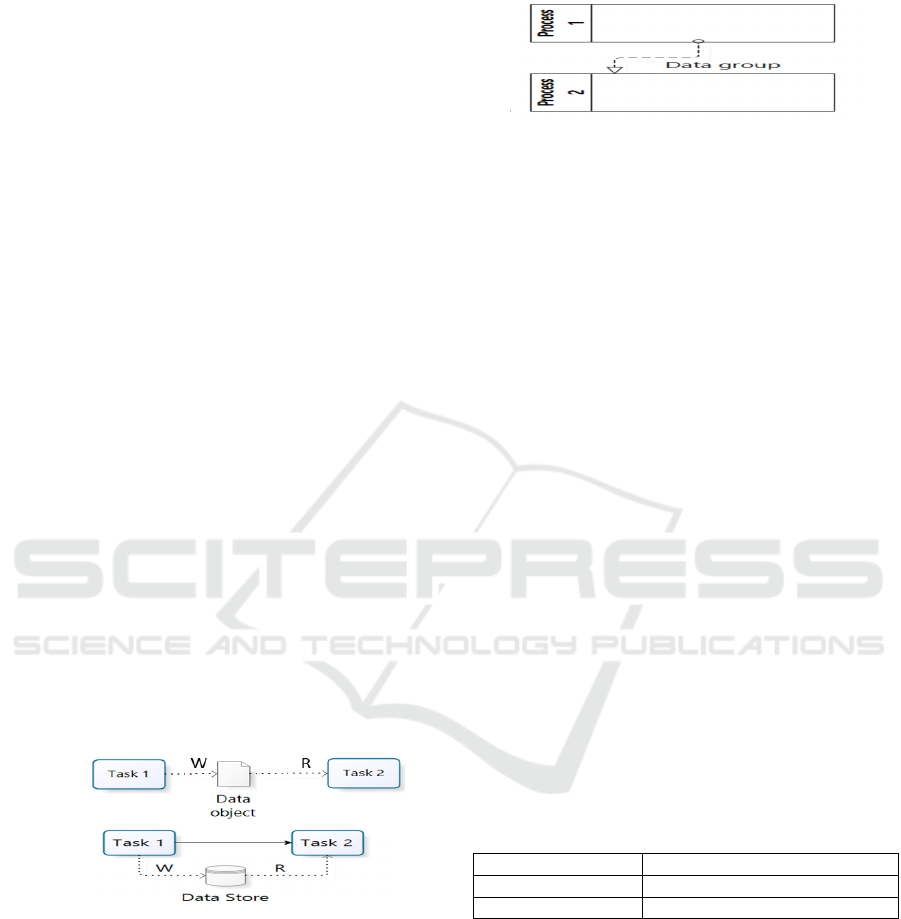
4.2.1 Read and Write Data Movements in a
BPMN Model
The Read and Write data movements are presented in
the sub-processes at the second level (dynamic level).
(a)
(b)
Figure 1: Read/Write data movements in a sub-process.
Figure 1 presents the Read and Write data
movements in a sub-process SP.
4.2.2 Entry and eXit Data Movements in a
BPMN Model
Entry and eXit data movements can exist in the
functional and dynamic levels. The number of Entries
(E) and eXits (X) represented in the BPMN models of
the various FP has to be modulated by the number of
data groups associated with each message or
sequence flow (See Figure 2).
Figure 2: Entry/eXit data movements in BPMN model.
Moreover, “Exception” corresponds to “Error
messages” in COSMIC. It is equivalent to one eXit.
4.3 Functional Size of BPMN Elements
Subject to Functional Changes
In this section, we present how to measure the FS of
a BPMN model. Two possible FC impact analysis
(internal and inter-level) in a BPMN model are
identified. In COSMIC method, a FC may include the
addition, the modification or the deletion of one or a
set of data movements (COSMIC, 2015).
4.3.1 Internal Impact of a Functional
Change in a BPM
Internal impact change is considered only within the
affected element and it does not propagate to any
other element in the model. Table 1 shows the FS of
an element subject to a FC. In this case, we can add,
modify or delete a FP in a BPM, where:
FSf(BPM): functional size of the BP model
after the change;
FSi(BPM): functional size of the BP model
before the change; and
FS(P): functional size of the process P.
Table 1: Functional Size of BPM in the Case of a FC -
Internal Impact.
Addition (P) FSf(BPM) = FSi(BPM) + FS(P)
Modification (P) FSf (BPM) = FSi(BPM)
Deletion (P) FSf(BPM) = FSi(BPM) - FS(P)
4.3.2 Inter-Level Impact of a FC
Table 2 presents the functional size (FS) of a task T
and a (sub) process P (SP) when a functional change
is needed, where:
FSf(T): the FS of T after the change;
FSi(T): the FS of T before the change;
FSf(P/SP): the functional size of P/SP after the
change; and
FSi(P/SP): the functional size of P/SP before
the change.
ICSOFT 2017 - 12th International Conference on Software Technologies
268

Table 2: Functional size of a task and its related (sub)
processes for the inter-level impact (parent) of a FC.
FC in a Task
Addition
(T)
Modification
(T)
Deletion
(T)
Pre Cond
Task T FSf(T) =
FSi(T) + 1CFP
FSf(T) =
FSi(T)
FSf(T)=
FSi(T)-1CFP
(sub)
Process
P/SP(taskp
arent)
FSf(P/SP) =
FSi(P/SP) +
1CFP
FSf(P/SP) =
FSi(P/SP)
FSf(P/SP)
=FSi(P/SP) -
1 CFP
Input data group
Task T
If [T
⊄
datagroup-in
then
FSf(T)=FSi(T)
+ 1CFP
else FSf(T) =
FSi (T)
FSf (T) =
FSi (T)
[T
⊄
datagroup-in
then
FSf (T) =
FSi(T) -
1CFP else
FSf(T) = FSi
(T)
(sub)
process
P/SP(taskp
arent)
If [T
⊄
datagroup-in
then FSf(P) =
FSi (P/SP) + 1
CFP else
FSf(P/SP) =
FSi(P/SP)
FSf(P) =FSi
(P)
[T
⊄
datagroup-in
then
FSf(P/SP) =
FSi (P/SP) -
1 CFP else
FSf(P/SP) =
FSi(P/SP)
Output data group
TaskT
If [T
⊄
datagroup-out
then
FSf(T)=FSi(T)
+1CFP
elseFSf(T) =
FSi (T)
FSf (T) =
FSi (T)
[T
⊄
datagroup-
out then
FSf (T) =
FSi(T) - 1
CFP
elseFSf(T) =
FSi (T)
(sub)
process
P/SP (task
parent)
If [T
⊄
datagroup-out
then FSf(P/SP)
= FSi (P/SP) +
1 CFP else
FSf(P/SP) =
FSi(P/SP)
FSf(P/SP)
=FSi (P/SP)
[T
⊄
datagroup-
out then
FSf(P/SP) =
FSi (P/SP) -
1 CFP else
FSf(P/SP) =
FSi(P/SP)
A FC that affects a task may lead to an impact not
only on the FS of the affected task but also the FS of
the related process (P). Since tasks are represented in
the dynamic level and processes are represented in the
functional level, therefore this change propagates
from the dynamic to the functional level (parent
impact). Note that a FC in a task may lead to an
impact only if it affects either: condition, input data
group or output data group.
When a FC affects a sequence/message flows or
object data in a (sub) process P/SP, it may lead to an
impact on the FS of P/SP and the FS of its tasks. In
this case, ‘inter-level impact’ (parent) direction is
required. For example, when the FC is the addition of
an object data between two tasks (Ti and Tj) in a (sub)
process P/SP, then we should add 2 CFP (W and R)
to the FS (P/SP), and 1 CFP to the FS of Ti and Tj.
Table 3: Functional size of a task and its related (sub)
processes in the case of inter-level impact (parent) of a FC.
FC in a (sub) process
Addition
(flow)
Modification
(flow)
Deletion
(flow)
object data
Task (Ti) FSf(Ti) =
FSi(T) +
1CFP
FSf(Ti) =
FSi(Ti)
FSf(Ti) =
FSi(Ti)-1
CFP
Task (Tj) FSf(Tj) =
FSi(Tj) +
1CFP
FSf(Tj) =
FSi(Tj)
FSf(Tj)
=FSi(Tj)-1
CFP
(sub)
rocess
P/SP (T’s
parent)
FSf (P/SP)
= FSi(P/SP)
+ 2 CFP
FSf(P/SP) =
FSi(P/SP)
FSf (P/SP)
= FSi
(P/SP) -
2CFP
Sequence flow
With condition
Task (Ti) FSf(Ti) =
FSi(Ti) +
1CFP
FSf(Ti) =
FSi(Ti)
FSf(Ti) =
FSi(Ti) -
1CFP
(sub)
process
P/SP
(task’s
parent)
FSf (P/SP)
= FSi(P/SP)
+ 1CFP
FSf(P/SP) =
FSi(P/SP)
FSf (P/SP)
= FSi
(P/SP)-
1CFP
Message flow with
data group
Task (Ti)
FSf(Ti) =
FSi(Ti) +
1CFP
FSf(Ti) =
FSi(Ti)
FSf(Ti) =
FSi(Ti) -
1CFP
(sub)
process
P/SP
(task’s
parent)
FSf (P/SP)
= FSi(P/SP)
+ 1CFP
FSf(P/SP) =
FSi(P/SP)
FSf (P/SP)
= FSi
(P/SP)-
1CFP
Table 3 presents the FS of a (sub) process P/SP
and its tasks (T
i
and/or T
j
) when a FC affects a flow
in a (sub) process, where:
FSf(Ti), FSf(Tj): the functional size of T
i
and Tj
after the change;
FSi(Ti), FSi(Tj): the functional size of T
i
and T
j
before the change;
FSf(P/SP): functional size of a (sub) process
P/SP after the change; and
FSi(P/SP): functional size of a (sub) process
P/SP before the change.
We note that, in the functional level, the deletion
of a sub process will generate the deletion of all its
tasks (dynamic level). In this case, ‘inter-level
impact’ (child) direction is required (Table 4). The
addition of a (sub) process requires only the internal-
impact direction as provided in Table 1. The
modification of a (sub) process is presented in Table
2 and Table 3. Table 4 presents the FS of the BPM
model and T (Task in a sub process SP) after a FC
proposing the deletion of a sub process SP, where:
FSf(BPM): functional size of BP model after
the change;
Analyzing Functional Changes in BPMN Models using COSMIC
269

FSi(BPM): functional size of BP model before
the change;
FSf(T): the functional size of T after the
change; and
FSi(T): the functional size of T before the
change.
Table 4: Functional size of a sub process SP and its related
tasks in the case of inter-level impact (child) of a FC.
FC = Deletion of a sub process SP
Task with
[Pre-
condition]
BPM model FSf(BPM) = FSi(BPM) -
FS(SP)
Task T (SP’s
child)
FSf(T) = FSi(T) - 1 CFP
Task with
input data
group
BPM model FSf(BPM) = FSi(BPM) -
FS(SP)
Task T (SP’s
child)
FSf(T) = FSi(T) - 1 CFP
Task with
output
data group
BPM model FSf(BPM) = FSi(BPM) -
FS(SP)
Task T (SP’s
child)
FSf(T) = FSi(T) - 1 CFP
4.3.3 FC Impact Analysis in a BPM
In order to determine how important is a FC, we
propose to identify the FC status based on its
functional size. In fact, a negligible change to a BP
model represents changes in “a few number of data
movements”. COSMIC considers that “the minimum
size of a change to a BP is 1 CFP” (COSMIC, 2015).
While, an important FC to a BP model represents
changes in “a big number of data movements”. Thus,
to determine the FC Status, we propose a threshold
value, noted AV
FC
that represents the average value
of the functional size of all functional processes in the
BPM. In fact, AV
FC
cannot be a fixed value. It
depends on the FS(BPM) and the number of the
functional processes in the changed BPM. AV
FC
is
calculated as provided by the following formula.
()
FC
F
SBPM
AV
n
=
(1)
where:
FS(BPM): functional size of the BPM; and
n: the number of functional processes in the
BPM.
As illustrated in Table 5, the identification of the FC
status in the BPM depends on its FS compared to
AV
FC
value. We distinguished between “in scope” FC
and “out of scope” FC (Fairly, 2009). “In scope” are
changes that can be accomplished with little or no
disruption to planned work activities. This
classification is based mainly on the FS(FC). If the
FS(FC) is less than or equal to the AV
FC
, then it may
produce none or low changes in the BPM. It is
considered as an “in scope” FC. If the FS(FC) is upper
than the AV
FC
, then it can lead to a potential impact on
the FS(BPM). It is classified as an “out of scope” FC.
Table 5: Identification of the FC Status in BPM.
FC Status in scope out of scope
FS(FC) = 1 CFP or ≤ AV
FC
> AV
FC
If the FS(FC) = 1 CFP or FS(FC) ≤ AV
FC
, then
the FC is classified as an “in scope” change. An
“in scope” FC can be accomplished with few or
no changes in the BPM life cycle progress.
If the FS(FC) > AV
FC
, then the FC is
considered as an “out of scope” FC. The
proposed FC affects a big number of data
movements. Thus, the FS(FC) exceed the value
of AV
FC
.
Analyzing the FC impact will be helpful in
decisions taken to answer the FC request. This
analysis allows also managers to assess how much
flexibility they have to justify acquiring additional
cost or delaying the BP project.
5 MEASURING THE FS OF A
BPM
Each fragment represents an execution scenario that
is instantiated in a lane/pool.
Therefore, at the functional level (the 1
st
level ), the
functional size FS of a BPM model M is equal to the
sum of the sizes of its fragments.
()
()
1
n
i
i
FS M FS F
=
=
(2)
where:
n is the total number of fragment F
i
in the BPM
M, (the 1
st
level: functional level); and
FS (Fi): the functional size of a fragment F
i
(2
end
level: dynamic level).
At the dynamic level, a fragment F
i
consists of a set
of business activities BA
ij
. Thus, the functional size
of a fragment F
i
is given by:
() ( )
()
1
Pr
m
iiij
j
F
S F FScond econd F FS BA
=
=+
(3)
where:
FS(F
i
): the functional size of the fragment F
i
(1
≤ i ≤ n);
m is the total number of BA
ij
detailing the
fragment F
i
(2
nd
level: dynamic level);
FS(BAij): the functional size of the business
activity BA
ij
(2
nd
level: dynamic level); and
ICSOFT 2017 - 12th International Conference on Software Technologies
270

FScond (Precond F
i
): functional size of the
precondition F
i
(1CFP if it exists).
To measure the FS(BA
ij
), we use formula (4):
() ( ) ( )
1
Pr
k
ij ij ijk
t
FS BA FScond econd BA FS SBA
=
=+
(4)
where:
FScond(Precond BA
ij
): the FS of the pre-
condition of BA
ij
(5).
FS(SBA
ij
): the functional size of the sub
business activity SBA
ij
(dynamic level).
()
1
Pr
0
ij
ij
CFP if BA has a pre condition
FScond econd BA
otherwise
−
=
(5)
To measure the FS(SBA
ijk
), we use formula (6):
() ( ) ()
1
Pr
p
ij ij ijk
l
FS SBA FScond econd SBA FS T
=
=+
(6)
where:
FS(SBA
ijk
): the FS of the sub business activity
(l ≤ ij ≤ p).
p: the number of tasks detailing the sub
business activities SBA
ij
(dynamic level).
FS(T
ijk
): the FS of a Task T
ijk
(dynamic level).
FScond(Pcond SBA
ij
): the FS of the pre-
condition of SBA
ij
(1CFP if it exists).
To measure the FS(T
ijk
), we use formula (7):
() ( ) ( )
Pr
ijk ijk ijk
FS T FScond econd T FSDatagp DatagpT=+
(7)
where:
FScond(Pcond T
ijk
): the FS of the pre-condition
of T
ijk
(1 CFP if it exists).
FSdatagp (datagp T
ijk
) = 1 CFP if T
ijk
includes
input or output data group.
To measure the functional size of a guard
condition, we use the following formula:
()
1
Pr
0
ijk
ijk
CFP if T has a condition
FScond econd T
otherwise
=
(8)
The functional size of an error (exception) is
always equal to 1 CFP (COSMIC, 2015). It is
measured according to the following formula:
1
()
0
CFP if thereis an error
FS E
otherwise
=
(9)
Each fragment can express the main scenario
(MS), the variations (VMS) and the exception of the
main scenario (EMS) as presented in section 2.2.
In all cases, the MS scenario must run
independently of the VMS and the EMS scenarios.
The MS may specify variation action sequences
(VMS) to be carried out if one of its actions cannot be
executed. The VMS scenario is executed once its
triggering event occurs, after which the MS may
resume its execution. Furthermore, when an error
arises, the execution of the MS is interrupted and the
EMS scenario is executed. As inferred in the BPM
description, the Functional Size (FS) of a fragment
varies between two values depending on the
execution of its scenarios (10):
() ()
1
ii
F
SF MaxF≤≤
(10)
1: the minimal value resulting from the
evaluation of the pre-condition of its MS.
Max (F
i
): the maximal value when all the VMS
of F
i
are carried out and the EMS is triggered
after the last action of the MS. In fact, if a VMS
occurs, its size should be added to the size of
MS. Similarly, when the MS cannot happen,
then an EMS will occur leading to the
execution of other actions specific to the EMS:
() ( ) ( ) ( )
iMSVMSEMS
FS F FS F FS F FS F=+ +
(11)
We note that the FS(F
i
) is calculated using
formula (5). In addition, the maximal value of
functional size of a fragment can be obtained from the
series of business activities (BA) when all the VMS
of BA are carried out and the EMS is triggered after
the last action of the MS (formula (2)).
6 ILLUSTRATIVE EXAMPLE
To illustrate the practical use of our approach, we
present an example of the “Supply management
process” model as shown in Figure 3.
Based on the decomposition approach, the model
is presented as a series of fragments (F
i
). The high
level (F
i
) corresponds to the pool “Supply
Management Process”. Each fragment may contain
one or more business activities documented using
Lauesen’s description (Table 6).
The functional size of a BPM M is equal to the
sum of the sizes of its fragments. According to
formula (2), the FS(BPM) is equal to:
FS(BPM) = FS(F1) + FS(F2) + FS(F3) + FS(F4) +
FS(F5) + FS(F6) + FS(F7) + FS(F10)
= 16 CFP
In order to illustrate the proposed impact change
analysis in the BPM, we propose the FC as showed in
Figure 4: We add the exception “Supplier list is
empty” in F3 and add the task “Select supplier”
allowing to read the supplier list. The proposed FC
lead to the addition of 2 CFP to the FS (F3). Thus, the
FS(F3) after the FC is equal to 4 CFP (Table 7). In
this case, the ‘inter-level impact (parent)’ analysis is
required. In fact, the FC that affects the task “Select
supplier” will lead to an impact on Task’s parent (F3).
This analysis is provided in Table 7.
As provided in Table 8, the FS(F3) before the FC
is equal to 2 CFP, and after the FC 4 CFP.
Analyzing Functional Changes in BPMN Models using COSMIC
271
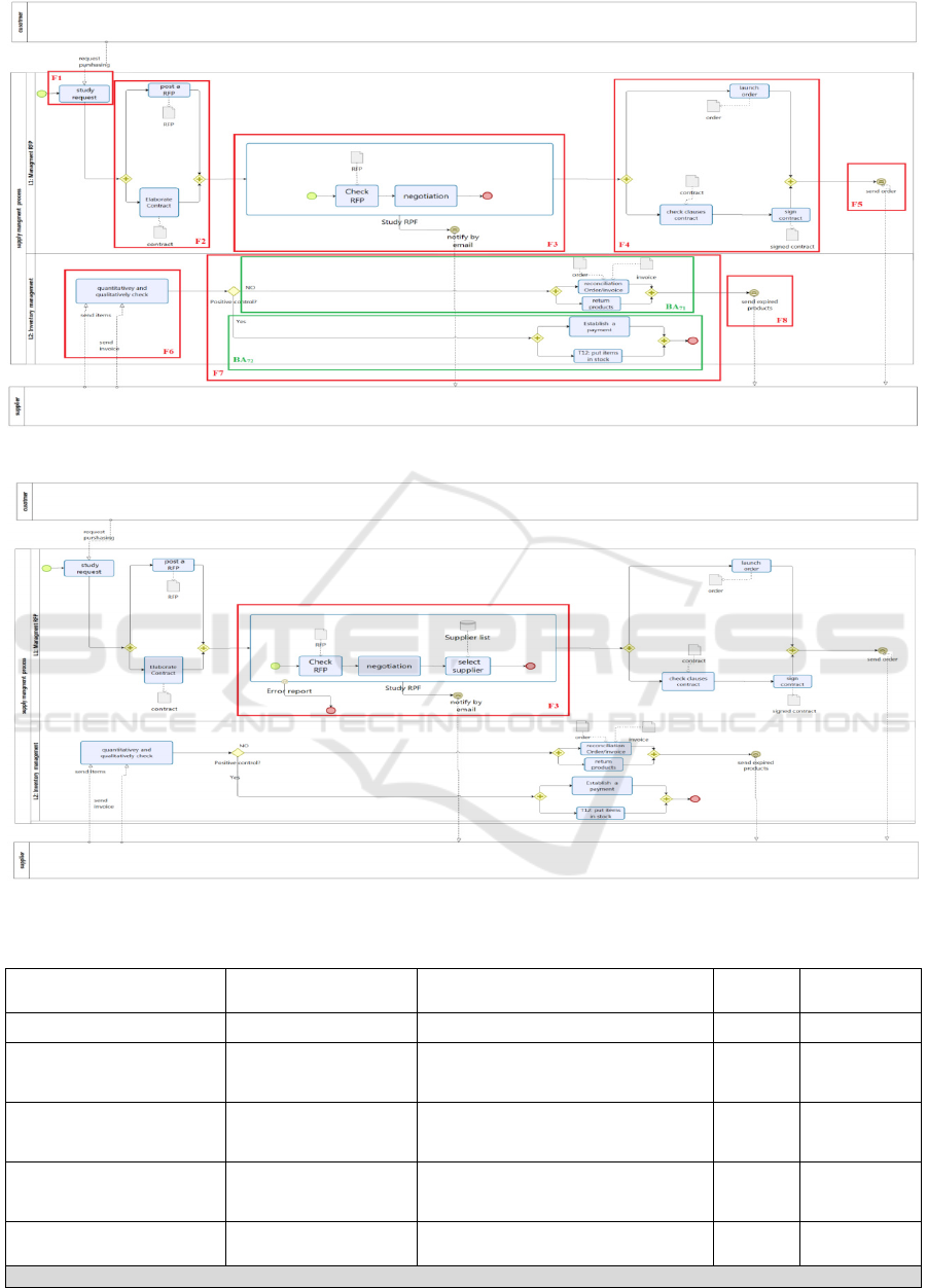
Figure 3: Decomposition of the BPM “Supply Management Process” before the change.
Figure 4: “Supply Management Process” after the change.
Table 6: Fragment description of F3 in the “Supply Management Process” BPM.
Business activities
Description FSM of Fragment Formulas
Measurement
results in CFP
Fragment name F3
() ( )
()
1
Pr
m
iiij
j
F
S F FScond econd F FS BA
=
=+
(2) 0 CFP
Purpose of the Business
activity
Select the supplier from
the supplier list
() ( )
()
1
Pr
ij ij
k
ijk
t
FS BA FScond econd BA
FS SBA
=
=+
(3) 0 CFP
Trigger/Precondition for
execution
Notify by email
() ( )
()
1
Pr
ij ij
p
ijk
l
FS BA FScond econd SBA
FS T
=
=+
(5) 1 CFP
Variants during execution
of the task and problems.
none
() ( )
()
Pr
ijk ijk
ijk
FS T FScond econd T
FSparam ParamT
=+
(6) 1 CFP
Sub-tasks and their
sequence
T4: check RFP
T5: negotiation
Total FS(F3) = 2 CFP
ICSOFT 2017 - 12th International Conference on Software Technologies
272

Table 7: ‘inter-level impact (parent)’ analysis on the functional size of F3.
Business activities
Description FSM of Fragment Formulas
Measurement
results in CFP
Fragment name F3
() ( )
()
1
Pr
m
iiij
j
F
S F FScond econd F FS BA
=
=+
(2) 0 CFP
Purpose of the
Business activity
Select the supplier from
the list
() ( )
()
1
Pr
ij ij
k
ijk
t
FS BA FScond econd BA
FS SBA
=
=+
(3) 0 CFP
Trigger/Precondition
for execution
Notify by email
() ( )
()
1
Pr
ij ij
p
ijk
l
FS BA FScond econd SBA
FS T
=
=+
(5) 1 CFP
Variants during
execution of the task
and problems.
Error Report
() ( )
()
Pr
ijk ijk
ijk
FS T FScond econd T
FSparam ParamT
=+
(6)
2 CFP
Sub-tasks and their
sequence
T4: check RFP
T5: negotiation
T6: select supplier
=
otherwise
erroranisthereifCFP
EFS
0
1
)(
(8) 1 CFP
Total FS(F3) = 4 CFP
Table 8. Measurement results for Supply management process before and after the change.
Before the change After the change
FP
Fragment Functional Sub-process E X W R CFP E X W R CFP
Supply management process
F1 T1: Study request 1 0 0 0 1 1 0 0 0 1
F2
T2: Post a RFP 0 0 0 1 1 0 0 0 1 1
T3: Elaborate contract 0 0 0 1 1 0 0 0 1 1
F3
T4: check RFP 0 0 0 0 0 0 0 0 0 0
T5: negotiation 0 0 0 0 0 0 0 0 0 0
T6: select supplier 0 1 0 1 2
1
1 0 2
4
F4
T7: Launch order 0 0 1 0 1 0 0 1 0 1
T8: Check clauses contract 0 0 0 1 1 0 0 0 1 1
T9: Sign contract 0 0 1 0 1 0 0 1 0 1
F5 Send order 0 1 0 0 1 0 1 0 0 1
F6 T10: Quantitatively check 2 0 0 0 2 2 0 0 0 2
F7
BA
71
T11:Reconciliation order/invoice 1 0 0 2 3 1 0 0 2 3
T12: Return products 0 0 0 0 0 0 0 0 0 0
BA
72
T13: Establish a payment 1 0 0 0 1 1 0 0 0 1
T14: Put items in stock 0 0 0 0 0 0 0 0 0 0
F10 Send expired products 0 1 0 0 1 0 1 0 0 1
Total 5 3 2 6 16 6 3 2 7 18
7 CONCLUSION
In this paper, we have first presented a top-down
decomposition method of BPM into fragments. This
method helps software designer/measurers to present
a fine-grain measurement for the BPM based on
COSMIC-FSM method. The proposed measurement
relies on the documentation of each fragment through
a set of scenarios that can be applied in the
requirements specification phase.
The second contribution of this paper is to provide
a functional change impact analysis for BPM. The
proposed FC impact analysis across two directions
(internal and inter level) and two modelling levels
(functional and dynamic). Based on the functional
size of the functional change, we determine whether
the change request is an “in scope” or an “out of
scope” change. The “in scope” can be handled
without changes to the BPM. The “out of scope”
change my lead to changes on the BPM. This
classification can be used to help the manager make
decisions to accept/deny or defer a change request.
Moreover, the FC status is identified based only
on the FS(FC). However, we believe that other factors
may interfere in identifying the importance of a FC
such as the preference of the change requestor, the
effort required to answer the change, etc. In addition,
the focus of this paper is only on the intra-dependency
Analyzing Functional Changes in BPMN Models using COSMIC
273

analysis of a FC in the BPM; in further work we plan
to focus on inter-dependency analysis.
REFERENCES
Bridgeland, D., M., Zahavi., 2009. Business Modeling -A
Practical Guide to Realizing Business Value. Morgan
Kaufman Publishers.Chapters1 and 2.
COSMIC 2015. Common Software Measurement
International Consortium. 2015. COSMIC Functional
Size Measurement Method, Version 4.0.1,
Measurement Manual.
De la Vara, J., Sánchez, J., 2009. BPMN-based
Specification of Task Descriptions: Approach and
Lessons Learnt. In REFSQ'09, 15th Intern. Conf..
Amsterdam, The Netherlands. pp 124-138.
De la Vara, J.L., 2011. Business Process-based
Requirements Specification and Object-Oriented
Conceptual Modelling of Information Systems. A thesis
for the degree of Doctor of Philosophy in Computer
Science.
Estrela, F.C., Ricardo, J., Maribel, Y.S., 2015. Bridging the
Gap between a Set of Interrelated Business Process
Models and Software Models. In ICEIS'15, 17th
International Conference on Enterprise Information
Systems. Barcelona, Spain.
Fairly, R.E., 2009. Managing and Leading Software
Projects.Wiley-IEEE Computer Society Press.
Grossmann, G., Schrefl., M., Stumptner, M., Modelling
Inter-Process Dependencies with High-Level Business
Process Modelling Languages, 5th Asia-Pacific
Conference on Conceptual Modelling, Wollongong,
NSW, Australia, pp. 89-102.
Haoues, M., Sellami, A., and Ben-Abdallah., H., 2016.
Functional Change Impact Analysis in Use Cases: An
Approach based on COSMIC Functional Size
Measurement. Science of Computer Programming,
Special Issue on Advances in Software Measurement.
ISO/IEC 19510. 2013. Information technology -- Object
Management Group Business Process Model and
Notation. 2013.
Javier, B., José, G.A., Cristina, V.C., Juan, M.M., 2014. A
Pattern-based and Model-Driven Approach for
Deriving IT System Functional Models from Annotated
Business Models. In ISD’14, 22nd International
Conference on Information Systems Development.
Seville, Spain. pp 319-332.
Jackson, M., 1995. Software Requirements &
Specifications: A Lexicon of Practice, Principles and
Prejudices. ACM Press/Addison-Wesley Publishing
Co., New York.
Kaya, M., 2010. E-cosmic: a Business Process Model based
Functional Size Estimation Approach. MSc Thesis.
Ankara, Middle East Technical University. August 15.
Li, J., Jeffery, D.R., Fung, K.H., Zhu, L., Wang, Q., Zhang,
H., Xu, X., 2012. A Business Process-Driven Approach
for Requirements Dependency Analysis, In BPM’12,
10th International Conference of Business Process
Management. Tallinn, Estonia, pp 200-215.
Lauesen, S., 2002. Software Requirements: Styles and
Techniques. Addison-Wesley, London.
Monsalve, C., April, A., Abran, A., 2012. On the
Expresiveness of Business Process Modeling Notations
for Software Requirements Elicitation. In IECON’12,
38th Annual Conference of the IEEE Industrial
Electronics Society. Montreal, Canada.
Pohl, K., 2010. Requirements Engineering: Fundamentals,
Principles, and Techniques. Springer, Heidelberg.
Sellami, A., Ben-Abdallah, H., 2009. Functional Size of
Use Case Diagrams: A Fine-Grain Measurement.
ICSEA’09, 4th International Conference on Software
Engineering Advances. Porto, Portugal. pp 282-288.
Siqueira, F.L., Muniz Silva, P.S., 2014. Transforming an
Enterprise Model Into a Use Case Model in Business
Process Systems. International Journal of Systems and
Software. pp152–171.
Uronkarn, W., Senivongse, T., 2014. Change Pattern-
Driven Traceability of Business Processes. In
IMECS’14, International Multi Conference of
Engineers and Computer Scientists. Hong Kong.
Wang, Y., Yang, J., Zhao, W., 2012. Change Impact
Analysis in Service based Business Processes. In
SOCA’12, International Conference on Service-
Oriented Computing and Applications. pp 131-149.
ICSOFT 2017 - 12th International Conference on Software Technologies
274
