
A New Particle Weighting Strategy for Robot Mapping FastSLAM
Luciano Buonocore
1
, Sérgio R. Barros dos Santos
2
, Areolino de Almeida Neto
3
,
Alexandre C. M. Oliveira
3
and Cairo L. Nascimento Jr.
2
1
Department of Electrical Engineering, Federal University of Maranhão, São Luís, MA, Brazil
2
Division of Electronic Engineering, Instituto Tecnológico de Aeronáutica, São José dos Campos, SP, Brazil
3
Department of Informatics, Federal University of Maranhão, São Luís, MA, Brazil
Keywords:
FastSLAM Filter, Particle Weighting, Mobile Robot.
Abstract:
Nowadays, FastSLAM filters are the most widely used methods to solve the Simultaneous Localization and
Mapping (SLAM) problem. In general, these approaches can use complex matrix formulation for computing
the particle weighting procedure, during the execution of the SLAM algorithm. In this paper, we describe
a new particle weight strategy for the FastSLAM filter, which can maintain the generation of particles in its
most simplified form. Thus, this approach tries to estimate the robot poses and build the environment map
using a simple geometric formulation for executing the particle weighting procedure. This method is capable
of reducing the processing time and keeping the accuracy of the robot pose. Both simulation and experimental
results demonstrate the feasibility of the proposed approach at enabling a robotic vehicle to accomplish the
mapping of an unknown environment and also navigate through it.
1 INTRODUCTION
In the past two decades, Simultaneous Localization
and Mapping (SLAM) approaches have been widely
employed due to, in part, the advances of sensors and
electronic devices (Castellanos, 1999),(Jessup, 2015).
Generally, SLAM is an approach in which mobile
robots can build a feasible map of the environment
and, at the same time, use this map for estimating its
localization. Note that the pose of the robot is com-
posed by information about its position and orienta-
tion (Dissanayake, 2001).
The major goal of SLAM is finding a suitable rep-
resentation of the environment, assuming that both the
map and robot pose are unknown. In this situation, the
vehicle must be able to move through the unexplored
environment which is populated with obstacles. Since
the vehicle has known motion and measurement mod-
els, the robot pose and obstacle locations can be suit-
ably estimated by the SLAM algorithm (Montemerlo,
2003b). For such, it is required the use of an appro-
priate sensory system for performing measurements
of the relative location between the vehicle itself and
obstacles (Brenneke, 2003).
The main contribution of this works is to propose a
direct approach to solve the particle weighting proce-
dure of a FastSLAM filter, using a simple mathemat-
ical formulation. Normally, the traditional methods
discussed in the literature involve complex matrix op-
eration, which takes into account the measurements
obtained at the current state and maintained by the
map (Montemerlo, 2003a).
In our proposal, we seek to reduce the complexity
of the weighting process by a simple verification of
the measured data. Several circles with different ra-
dius whose centers are defined by the raw measures
are used to accomplish the comparison between the
sensor data at each state of the filter and the raw mea-
surements stored by each particle. Observe that the
circles are employed because the 2D mapping are ap-
plied to produce the environment map.
Hence, if a measure obtained at a given state
is within the circle then the matching occur, i.e.,
the probability (weight) of the particle is increased.
Through this procedure, it is possible to define the
best relationship between the processing time and ac-
curacy of the contours of the map incurred during the
environment mapping.
This paper is organized as follows. In Section
2, we describe the general concepts involved in the
problem. Section 3 discusses the probabilistic mo-
tion model used. Section 4 introduces the proposed
weighting strategy to estimate the probability of each
particle. Subsequently, in Section 5 is presented the
322
Buonocore, L., Santos, S., Neto, A., Oliveira, A. and Jr., C.
A New Particle Weighting Strategy for Robot Mapping FastSLAM.
DOI: 10.5220/0006421903220328
In Proceedings of the 14th International Conference on Informatics in Control, Automation and Robotics (ICINCO 2017) - Volume 2, pages 322-328
ISBN: Not Available
Copyright © 2017 by SCITEPRESS – Science and Technology Publications, Lda. All rights reserved

obtained outcomes in both simulated and experimen-
tal trials. Finally, the conclusions and future work are
presented in Section 6.
2 PRELIMINARIES
2.1 FastSLAM Filter Overview
In the mobile robotics literature, two FastSLAM filter
approaches are addressed to solve the mapping and
localization problems. These approaches are classi-
fied as FastSLAM 1.0 and 2.0. The essential differ-
ence between them is that the version 2.0 has a model
of particle generation more complex than version 1.0
(due to the fact that this algorithm includes the mea-
surements performed at each sampling stage) which
results in a higher computational cost. Other major
aspects of both FastSLAM algorithms are described
in (Montemerlo, 2003a), (Thrun, 2004) and (Monte-
merlo, 2003c) .
Actually, some recent works use an open-source
algorithm based on Rao-Blackwellized Particle Filter
(known as Gmapping) for creating 2D occupancy grid
maps from laser scanner data and also to estimate the
robot pose in a target environment (Santos, 2013).
In this research, we use the FastSLAM 1.0 due
to this approach allows to maintain the generation of
particles in its most simplified form. The used Fast-
SLAM algorithm is represented by 100 particles.
In general, the FastSLAM 1.0 is composed by four
stages briefly described below:
1. Particle sampling: At this stage, the particles are
sampled based on a specific Probability Density
Function (PDF);
2. Particle weighting: Each sampled particle is
weighted according to the current environmental
measurements;
3. Map Update: The embedded map in the particles
are updated using the measurements (generated
by the sampling process) at each pose in the en-
vironment;
4. Particle Resampling: The particles are redis-
tributed based on their weights. The goal is to
keep only the set of particle associated with the
greater weights (probabilities).
The FastSLAM filter can be used to deal with the
noises resulting from the motion of the robot. These
noises are generated through the kinematic motion
model described in section 3 and are used to estab-
lish the new set of particles.
The measurements obtained from the current
robot pose are processed by the filter to define the
weight of each particle. This weight reflects the prob-
ability value related to each one of the particles. Note
that the probability represents each hypothesis chosen
by the algorithm (i.e., the quality of the pose repre-
sentation). In this work, we propose a new particle
weighting strategy (described in section 4) to deter-
mine the weight of each particle that composes the
FastSLAM algorithm.
2.2 Mapping Representation
In this work, SLAM problem for medium-scale envi-
ronments based on metric map representation is inves-
tigated. In our proposed solution, the location-based
map (defined by a 2D occupancy grid) is used to build
the map of the environment. This approach uses the
position information of each feature in the environ-
ment to define the map. In practice, each cell of the
map can assume three different representations: the
cells previously investigated by the robot is denomi-
nated as free or occupied space and is represented by
0 or 1, respectively; and the cells that have not yet
been verified by the robot is denominated as unknown
space and is represented by 0.5.
2.3 Simulation and Experimental
Context
This research was divided into two distinct phases:
simulation evaluation and experimental validation. In
the first stage, we conduct the evaluation trial by a
simulation setup. This setup consist of a computer
used to simultaneously run the SLAM algorithm (im-
plemented in the Matlab), and also the dynamic model
of the robot (KUKA youBot) and environment (im-
plemented in the Virtual Robot Experimentation Plat-
form - VREP). The interface between both software
was performed using the Robot Operating System
(ROS) network.
In the second stage, the developed SLAM algo-
rithm (implemented in Matlab) is validated using the
real robot (KUKA youBot) equipped with a Laser
Scanner (Hokuyo URG-04LX-UG01). The data ex-
change between the Matlab and the KUKA youBot is
performed by the ROS Network. The experimental
environment was equipped with four infrared camera.
These cameras were used to detect the robot pose in
relation to the global reference frame.
Both setups (Matlab/V-REP and Matlab/real
robot) provide an easy-to-use interface that allow
evaluating the FastSLAM algorithm in simulation,
A New Particle Weighting Strategy for Robot Mapping FastSLAM
323

and then export the code (filter algorithm) to the ac-
tual robot for performing the final verification.
3 PROBABILISTIC MOTION
MODELS
Let us consider a motion model given by (1) to es-
timate the robot pose at each instant of time (Thrun,
2005). In this approach, we use the motion model
based on velocity-based model which depends on
the speed and time elapsed during the route (Thrun,
2005).
p(x
t
|u
t
,x
t−1
) (1)
where t is the discrete time to estimate the next
state, x
t−1
is the previous particle state (pose and
map), u
t
is the command to move the robot and x
t
is
the next particle state. Note that noises are considered
during robot motions.
3.1 Velocity Motion Model
The amount of time to perform the commanded move-
ment is fundamental to predict the robot displace-
ment. In this approach, we estimate the probability
of the next pose over a fixed interval of time.
Let u
t
be the robot control input composed by two
different commands. v
t
is used to perform the lin-
ear movements and ω
t
is used to execute the angu-
lar movements. These parameters can be related as
shown in (2).
u
t
=
v
t
ω
t
(2)
The use of velocity-based model allows generat-
ing curved paths whereas the odometry-based models
only produce simple linear or angular motions (this
feature precludes the application of a planning tra-
jectory algorithm) (Thrun, 2005). In order to use the
velocity motion models, it is necessary to define the
noises relative to the linear and angular motions, and
also the final orientation error at the pose.
4 PARTICLE WEIGHTING
APPROACH
In this section, we present the proposed strategy for
performing the particle weighting using the sensor
data and raw measurements obtained from the en-
vironment. Initially, the set of particles is gener-
ated (particle sampling) using a Gaussian function.
Hence, the weighting process can be executed from
the sampled particles. The Box-muller function also
was tested in the algorithm. However, the Box-muller
function has not presented good estimation.
The particle weighting procedure is accomplished
by a matching process which uses the raw measure-
ments acquired at the current state to verify whether
the measures (obtained by the robot sensor) are al-
ready stored in each one of the generated particles.
Thus, if this condition is true, the weight of the parti-
cles increases. Otherwise, the weight is not changed
and the measures (which have not been verified) are
included to the raw measurements of the evaluated
particle.
In this approach, the measures (acquired at the
current state and also stored in the particles) are de-
rived from the raw measurements. The raw measure-
ments are obtained from the laser scanner (consider-
ing the particle bearing), and are represented by the X
and Y coordinates in relation to the global reference
frame. In practice, the raw measurements are consid-
ered to estimate the weight of the set of particles.
Let us consider that each one of the particles i =
{
1,...,100
}
generated at a specific state s can be de-
fined as,
p
i
(s) =
{
α
s
,ω
s
,γ
s
}
∀s = {1, ...,N} (3)
where α corresponds to the pose vector defined
by
x
1:s
y
1:s
θ
1:s
T
, ω is the vector used to keep
the raw measurements obtained from the environment
and γ refers to the local occupancy grid (metric map),
which is defined by a matrix of 200 x 200. Note that
the subscript (1 : s) of the pose vector corresponds to
the set of measures of all observed states.
In this proposal, we consider that the local occu-
pancy grid is composed by cells that have 10 cm of
side length. All particles are composed by the same
map representation, which are updated during the ex-
ploration process. This approach can be extended for
large environments through the hybrid map scheme
discussed in (Stachniss, 2006).
Observe that the updating time (of the global map)
is related to the size of the environment and the num-
ber of particles used at each state.
Let us consider that the robot moves from an ini-
tial pose to the next pose using the velocity-based
motion model, and then executes the measurements
using the laser scanner. The measurements are per-
formed through a scanning of 180 degree at the pose.
The obtained raw measures are used to accomplish the
weighting procedure through the matching function.
The match function is used to select the most
promising measures stored by the particles using the
measurements (obtained by the laser scanner) at the
ICINCO 2017 - 14th International Conference on Informatics in Control, Automation and Robotics
324
current pose. The verification of this measures (for
each particle i) is realized using a simple geometric
formulation described in (4), which employs a set of
circles whose centers are defined by the raw mea-
sures. Note that these circles can assume different
radius values.
ϑ
j
=
(
1 i f m(.) ∈ f (c, r)
0 i f m(.) /∈ f (c, r)
(4)
where j = {0, 1, 2,...,N
e
} denotes the vector
length and N
e
is the total number of elements of the
vector ω (see (3)). m refers to the raw measures ac-
quired from the laser scanner sensor, f (c,r) is the
circle function that depends on the center c and radius
r. In this work, the radius of the circle can be referred
by radius matching.
The radius values were defined using the good ac-
curacy of laser scanner measurements. The selected
values for performing the matching procedures were
0.1, 1 and 2. Observe that r can be tuned to obtain
the best relationship between the processing time and
accuracy of the map contours.
Then, if ϑ = 1, the measure is within the circle
and the matching occur. On the other hand, if ϑ = 0,
the measure is out of the circle and the matching does
not occur. Thus, the measures that receive ϑ = 0 are
included in the vector (ω) of raw measurements of the
evaluated particle. Note that the vector (ω) grows up
with the time of exploration and with the use of small
radius matching values.
The quantity of matching occurred in a specific
particle i can be computed as follows:
η
i
=
N
e
∑
j=1
ϑ
j
(5)
where η
i
is the quantity of matching occurred in a
particle i.
The weight of each particle is calculated through
the relation between the amount of matching occurred
in the particle i and the total amount of matching of
all particles of the filter. Let us define this procedure
as follows:
w
i
= η
i
/η (6)
where w
i
is the weight of the particle i and η is the
total number of matching obtained by the particles of
the fastSLAM filter.
After finishing the weighting process, the local oc-
cupancy grid map of the particles is updated, and then
all promising hypotheses (resampling procedure) are
used by new set of particles (that are generated at the
next states).
5 EVALUATION AND
DISCUSSION
In this section, we present the results obtained during
the evaluation of the FastSLAM filter which employs
the particle weighting strategy developed in section 4.
The trials were divided into two distinct parts: simu-
lation and experimental analysis. In both case, we use
the same scenario, sensors and robot to conduct the
trials. Note that the simulated and experimental envi-
ronments were described in section 2.3.
5.1 Simulation Results
The aim of simulation trial is to demonstrate the eval-
uation of the particle weighting strategy in relation to
the general aspects of the FastSLAM filter. In this sec-
tion, we analyze the accuracy of the poses and built
map, the number of the raw measures stored by the
particles and the processing time of the filter. The
simulation tests were performed using three different
values for the matching radius - see (4). These param-
eters were adjusted to 0.1, 1 and 2 cm.
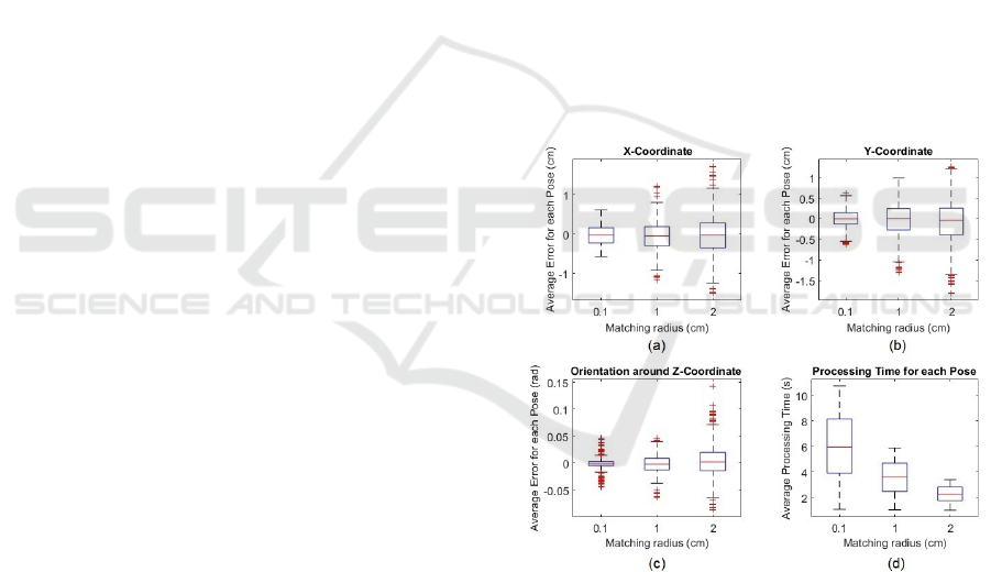
Figure 1: Box plot of the average pose errors and processing
time.
The datasets obtained through 10 different trials
were used to evaluate the FastSLAM algorithm. The
box plot in Figure 1 illustrates the average errors and
the average processing time distributions incurred by
each one of the matching radius. Note that the av-
erage error refers to the difference between the pose
estimated by the filter and the exact pose provided by
the V-REP simulator, during the exploration process.
Figures 1(a)(b)(c) show that the obtained average
pose error (X and Y coordinate and orientation) grows
up with the increasing of the matching radius value.
A New Particle Weighting Strategy for Robot Mapping FastSLAM
325
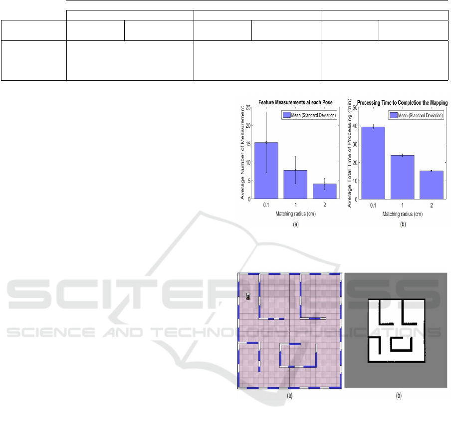
Table 1: Numerical Comparison between the Simulation and Experimental data for the matching radius of 1 cm.
Mapping and Localization Data
X-Position error Y-Position error Bearing error
Measures
Simulation
Trial
Experimental
Trial
Simulation
Trial
Experimental
Trial
Simulation
Trial
Experimental
Trial
Mean -0.05799 0.2540 -0.03063 -0.2836 -0.001688 -0.002091
Std. Dev. 0.3942 1.5785 0.4289 1.5202 0.01679 0.04551
Lower Value -1.1743 -2.6433 -1.3089 -2.6264 -0.06331 -0.09424
Upper Value 1.2104 2.6223 0.9856 2.3699 0.04635 0.1189
Observe that the smallest error occurs when is used
the matching radius of 0.1 cm. Note that the accu-
racy of the map is related to the value of the matching
radius selected by the user.
Through the trial results, we observe that the use
of matching radius equal to 1 cm provides a accept-
able average error and, respectively, a good accuracy
of the map for the navigation purpose. This condi-
tion is not observed for matching radius values greater
than 1 cm.
Table 1 presents the results obtained for the
matching radius of 1 cm. Note that the average error
presents (Table 1) small variation between the lower
and upper values and also small standard deviation for
the X and Y coordinate and orientation.
However, in Figure 1(d), it can be seen that the av-
erage time processing for each pose has an opposite
effect to the others shown in Figures 1(a)(b)(c). This
is due to the variation of the radius using in the match-
ing process, defined by (4). Thus, it is possible assert
that the time processing is reduced in function of the
increasing of the matching radius, since the amount
of stored measures by the particles at each pose is
also reduced. Note that the higher average process-
ing times occur when is used a radius of 0.1 cm.
Figure 2 shows the average number of measure-
ments accomplished at each pose and the average pro-
cessing time to completion the build of the environ-
ment map. Observe that, the amount of measure-
ments performed by the robot and the time required
to execute the exploration are reduced according to
the matching radius. These parameters have greater
values when was used radius of 0.1 cm.
The choice of the appropriate radius matching
must be done so that maximizes the accuracy of the
estimated poses and minimizes the total processing
time of the filter (cost of processing - overhead).
In Figure 2, we can see that the most promising
solution occurs when the radius is equal to 1 cm. Fig-
ure 3 illustrates the environment (with area of 100 m
2
)
used in simulation and the map built by the filter based
on location-based approach (using radius of 1 cm to
perform the weighting of the particle).
Now, we are going to present the experimental re-
sults of the FastSLAM filter using the proposed par-
Figure 2: Number of measurements performed by the robot
and the total processing time for the exploration and map-
ping.
Figure 3: Visual representation: (a) Simulated environment
and (b) Built map.
ticle weighting process. The experimental trial was
performed using the matching radius of 1 cm. This
value was chosen based on evaluation of the simula-
tion results.
5.2 Experimental Results
The aim of experimental trial was to demonstrate the
feasibility of the particle weighting strategy in SLAM
System. In order to evaluate the outcomes result-
ing from the exploration and mapping procedures, we
carry out 10 experiments in an actual environment.
Figure 4 shows the results obtained from one of the
performed trials. These graphs display the relative er-
ror between the actual and estimated poses in the X
ICINCO 2017 - 14th International Conference on Informatics in Control, Automation and Robotics
326
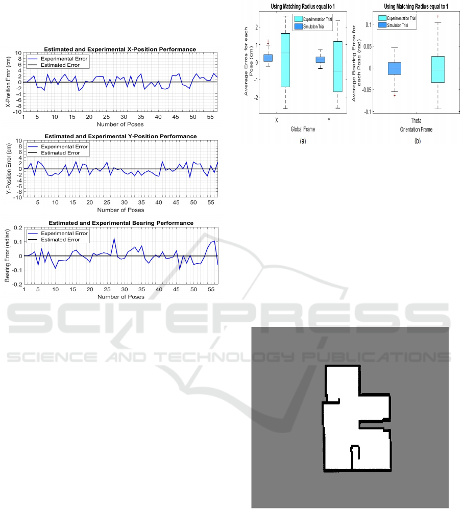
and Y coordinates and orientation. Observe that the
actual poses of the robot was obtained through the use
of a motion capture system based on infrared cameras.
Figure 4: Errors between actual and estimated poses.
Although the errors (for each pose) obtained from
the actual experiments (around +/- 3 cm for position
and +/- 0.12 degree for orientation) are higher than
the acquired from the simulation, the real results re-
mained within acceptable limits to execute the navi-
gation by the environment.
The box plot in Figure 5 presents the comparison
between the average errors for each pose. Figure 5(a)
illustrates the average errors in X and Y coordinates
while in Figure 5(b) displays the errors produced by
the orientation measurements. Note that the orien-
tation error have similar mean values in both trials.
However, the lower and upper values of the actual
bearing errors are greater than the bearing error ac-
quired by the simulations.
In respect to the average pose error (Figure5(a)),
we can assert that the difference of magnitude be-
tween the simulation and experimentation trials is
caused by the motion noises generated by the actual
robot.
The numerical values of the average error ac-
quired from the experimental trials are summarized
in Table 1. Note that the experiments have a low stan-
dard deviation for all parameters. This situation indi-
cates that the set of data are bunched up and close to
the mean. In other words, at any time incurred dur-
ing the experiments, the filter has not produced errors
Figure 5: Average errors obtained in X and Y axes and ori-
entation.
with outliers much larger than the general averages.
From this data, we can say that the filter is capable of
providing consistent results and also it is possible to
assert that the filter has not diverged during its time
operation.
Figure 6 displays the map built from the real en-
vironment using the FastSLAM filter which uses the
new approach to accomplish the weighting of the par-
ticles. In actual experiments, we use an environment
setup with reduced dimensions in comparison to the
simulated environment. It was necessary due to the
restriction of range of the employed cameras system.
Figure 6: Estimated map obtained by the FastSLAM filter
during the experimental validation.
6 CONCLUSIONS AND FUTURE
WORKS
In this paper was presented a new particle weight-
ing approach for FastSLAM filter which uses a sim-
ple geometric verification to determine the robot pose
A New Particle Weighting Strategy for Robot Mapping FastSLAM
327

and build the environment map. From this method,
the raw measures stored by the particles can be eas-
ily evaluated using the measurements obtained by the
robot sensor. Moreover, this approach enables to
implement several path planning techniques for the
robot to autonomously execute the exploration of the
environment.
Future works in this research include applying
optimization and artificial intelligence techniques for
generation of the path planning and for merging mul-
tiple sensor data. Our goal is to investigate a meta-
heuristic method which is capable of producing the
optimal paths to perform the SLAM and use a neural
network to merge the kinect and laser scanner data.
Thus, the system will be able to detect multi-sized ob-
jects present in the environment.
Other work alternatives include: a) the use of
metaheuristics to define the value of the radius of the
circle (matching phase); and b) evaluate the perfor-
mance of the proposed filter in larger scale environ-
ments and then to compare the real and estimated
maps.
ACKNOWLEDGEMENTS
The authors gratefully acknowledge the support for
this research provided by FAPEMA (Research Grant
No 44/2013-APCInter) and Federal University of
Maranhão (UFMA).
REFERENCES
Brenneke, C.; Wulf, O. W. B. (2003). Using 3d laser range
data for slam in outdoor environments. In IEEE Intel-
ligent Robots and Systems, pp. 188-193.
Castellanos, J.; Montiel, J. N. J. T.-J. (1999). The SPmap: A
probabilistic framework for simultaneous localization
and map building. IEEE Transactions on Robotics and
Automation, vol. 15, no. 5, pp. 948–953.
Dissanayake, M.; Newman, P. C. S. D.-W. H. C. M. (jun.
2001). A solution to the simultaneous localisation and
map building (SLAM) problem. IEEE Transactions on
Robotics and Automation, vol. 17, no. 3, pp. 229-241.
Jessup, J.; Givigi, S. B. A. (April 2015). Robust and Effi-
cient Multirobot 3-D Mapping Merging with Octree-
Based Occupancy Grids. IEEE Systems Journal.
Montemerlo, M. (2003a). FastSLAM: A Factored Solution
to the Simultaneous Localization and Mapping Prob-
lem with Unknown Data Association. Ph.D. disser-
tation, Dept. Elect. Eng., Robotics Institute, Carnegie
Mellon University.
Montemerlo, M.; Thrun, S. (2003b). Simultaneous local-
ization and mapping with unknown data association
using fastslam. In IEEE International Conference on
Robotics and Automation, pp. 1985–1991.
Montemerlo, M.; Thrun, S. K. D. W.-B. (2003c). Fast-
slam 2.0: An improved particle filtering algorithm for
simultaneous localization and mapping that provably
converges. In International Joint Conference on Arti-
ficial Intelligence, pp. 1151–1156.
Santos, J.; Portugal, D. R. R. (2013). An evaluation of 2d
slam techniques available in robot operating system.
In IEEE International Symposium on Safety and Res-
cue Robotics, pp.1-6.
Stachniss, C. (Apr. 2006). Exploration and Mapping
with Mobile Robots. Albert Ludwigs University of
Freiburg, PhD Thesis.
Thrun, S.; Montemerlo, M. K. D. W.-B. N. J. N. E. (2004).
An Efficient Solution to the Simultaneous Localization
and Mapping Problem with Unknown Data Associa-
tion. Journal of Machine Learning Research,.
Thrun, S.; Burgard, W. F. D. (2005). Probabilistic Robotics.
The MIT Press.
ICINCO 2017 - 14th International Conference on Informatics in Control, Automation and Robotics
328
