
Distortion Correction of Laser Scan Data from In-vehicle Laser
Scanner based on Kalman Filter and NDT Scan Matching
Kimiaki Inui
1
, Masahide Morikawa
1
, Masafumi Hashimoto
2
and Kazuhiko Takahashi
2
1
Graduate School of Doshisha University, Kyotanabe, Kyoto 6100321, Japan
2
Faculty of Science and Engineering, Doshisha University, Kyotanabe, Kyoto 6100321, Japan
Keywords: Laser Scanner, Laser-scan Data, Distortion Correction, Kalman Filter, NDT Scan Matching.
Abstract: This paper presents a Kalman-filter-based method of correcting distortion in 3D laser-scan data from in-
vehicle multilayer laser scanner. A robot identifies its own 3D pose (position and attitude) in a laser-scan
period using the normal-distributions transform (NDT) scan-matching method. Based on the pose
information, the robot’s pose is predicted and smoothed in a period shorter than the scan period using
Kalman filter under the assumption that the robot moves at nearly constant linear and turning velocities. The
predicted and smoothed poses of the robot are applied to map laser-scan data onto a world coordinate frame.
Subsequently, the robot again identifies its own 3D pose from the mapped scan data using NDT scan
matching. This iterative process enables the robot to correct the distortion of laser-scan data and accurately
map the laser-scan data onto the world coordinate frame. Experimental results of mapping a signal light in a
road environment validate the proposed method.
1 INTRODUCTION
Environment recognition using onboard laser
scanners is an important issue in the fields of mobile
robotics and vehicle automation (Mukhtar et al.,
2015). Several recognition methods using single-
layer or multilayer laser scanners have been
proposed, such as simultaneous localization and
mapping (SLAM) (Hess et al., 2016, Cadena et al.,
2016), map building (Yokoyama et al., 2013), and
moving-object tracking (Mertz et al., 2013, Kanaki
et al., 2016).
In environment recognition systems using
onboard laser scanners, laser measurements (laser-
scan data) are captured in a sensor coordinate frame
and mapped onto a world coordinate frame using the
robot’s pose information. The laser scanner obtains
range measurements by scanning laser beams; thus,
when the robot moves, all the scan data within a
scan cannot be obtained at the same position of the
robot. Therefore, if all the scan data obtained within
one scan is mapped onto the world coordinate frame
using the robot’s pose information, a distortion
arises in the scan data. To correct this distortion, the
robot’s pose should be determined more frequently
than the laser-scan period, i.e., for every laser
measurement in the scan.
Many methods for correcting distortion in scan
data have been proposed. Brenneke (Brenneke, et
al., 2003) corrected scan-data distortion by
estimating the robot’s pose in a short period based
on the information from global navigation satellite
systems (GNSSs) and inertial measurement units
(IMUs). Other methods (Hong et al., 2010,
Moosmann and Stiller, 2011, Zhang and Singh,
2014) have been proposed that reduce scan-data
distortion by estimating the robot’s pose using only
the laser-scan data, i.e., without using GNSS and
IMU data. These methods were used to calculate the
robot’s pose for each laser-scan period using the
iterative closest-points (ICP) scan-matching method
(Besl and McKay, 1992) and its variants and to
estimate the robot’s pose in a period shorter than the
scan period using linear interpolation under the
assumption that the robot moves at nearly constant
velocity.
In this paper, we present a distortion-correction
method for scan data using only laser scanner.
Normal distributions transform (NDT) scan
matching (Biber and Strasser, 2003) is applied to
estimate the robot’s pose. As the NDT scan matching
method has a lower computational cost than the ICP
method, it can easily process large amounts of scan
data captured from a multilayer laser scanner. In
addition, the robot’s pose is estimated in a period
Inui, K., Morikawa, M., Hashimoto, M. and Takahashi, K.
Distortion Correction of Laser Scan Data from In-vehicle Laser Scanner based on Kalman Filter and NDT Scan Matching.
DOI: 10.5220/0006422303290334
In Proceedings of the 14th International Conference on Informatics in Control, Automation and Robotics (ICINCO 2017) - Volume 2, pages 329-334
ISBN: Not Available
Copyright © 2017 by SCITEPRESS – Science and Technology Publications, Lda. All rights reserved
329
shorter than the laser-scan period using Kalman
filter. Since the Kalman-filter-based robot
localization is commonly used in mobile robotics
and vehicle automation, the scan-data distortion in a
Kalman-filter framework can be easily embedded
into the self-localization system of the robot.
The rest of this paper is organized as follows. In
Section 2, an overview of the experimental system is
given. In Section 3, scan-data mapping based on
NDT scan matching is summarized. In Section 4, a
distortion-correction method for scan data using the
Kalman filter is described. In Section 5,
experimental results are presented, followed by
conclusions in Section 6.
2 EXPERIMENTAL SYSTEM
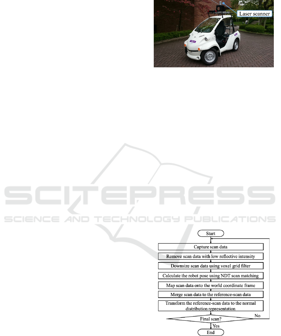
Figure 1 shows the mobile robot equipped with a 32-
layer laser scanner (Velodyne HDL-32E). The
maximum range of the laser scanner is 70 m, the
horizontal viewing angle is 360° with a resolution of
0.16°, and the vertical viewing angle is 41.34° with a
resolution of 1.33°.
The laser scanner provides 384 measurements
(the object’s 3D position and reflection intensity)
every 0.55 ms (at 2° horizontal angle increments).
The period for the laser-scanner beam to complete
one rotation (360°) in the horizontal direction is 100
ms, and 70,000 measurements are obtained in one
rotation.
In this paper, one rotation of the laser-scanner
beam in the horizontal direction (360°) is referred to
as one scan, and the data obtained from this scan is
referred to as scan data. Moreover, the laser
scanner’s scan period (100 ms) is denoted as
τ
and
scan data observation period (0.55 ms) as
τ
Δ
.
3 SCAN-DATA MAPPING
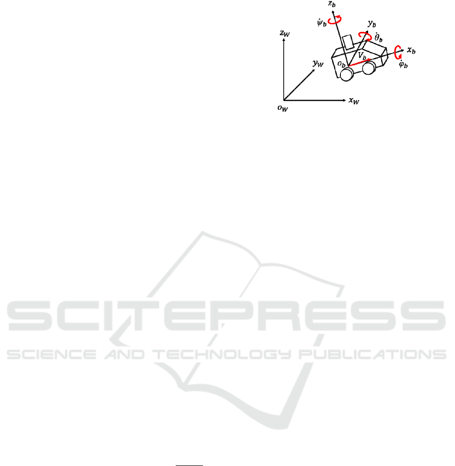
Figure 2 shows the process for scan-data mapping
using NDT scan matching. First, the scan data
related to the ground is removed based on the
reflection intensity of the scan data, and the
remaining scan data is mapped onto a 3D grid map
(a voxel map) represented in the robot’s coordinate
frame,
b
Σ
. A voxel grid filter (Munaro et al., 2012)
is applied to downsize the scan data. The voxel used
for the voxel grid filter is a tetrahedron with a side-
length of 0.2 m.
In the world coordinate frame,
W
Σ
, a voxel map
with a voxel size of 1 m is used for NDT scan
Figure 1: Overview of the experimental robot.
matching. For the i-th (i = 1, 2, …n) measurement in
the scan data, we define the position vector in
b
Σ
as
bi
p
and that in
W
Σ
by
i
p
. Thus, the following
relation is given:
=
1
)(
1
bii
p
XΤ
p
(1)
where
T
zyx ),,,,,(
ψθφ
=X is the robot’s pose.
T
zyx ),,(
and
T
),,(
ψθφ
are the 3D position and
attitude (roll, pitch, and yaw angles) of the robot,
respectively, in
W
Σ
. T(X) is the following
homogeneous transformation matrix:
−
−+
+−
=
1000
coscoscossinsin
cossinsinsincoscoscossinsinsinsincos
sinsincossincossincoscossinsincoscos
)(
z
y
x
Τ
θφθφθ
ψφψθφψφψθφψθ
ψφψθφψφψθφψθ
X
Figure 2: Process of scan data mapping using NDT scan
matching.
The scan data obtained at the current time
τ
t
(t =
0, 1, 2, …)
,
{}
)()(
2
)(
1
)( ,,, t
bn
t
b
t
b
t
b
pppP =
or
,{ )(
1
)( tt pP =
,,)(
2
tp
})(t
n
p
, are referred to as the new input scan,
and the scan data obtained in the previous time
ICINCO 2017 - 14th International Conference on Informatics in Control, Automation and Robotics
330
before
τ
)1( −t
,
{}
)1()1()0( ,,, −= tPPPP
, is referred to
as the reference scan.
NDT scan matching (Biber and Strasser, 2003)
conducts a normal distribution transformation for the
reference-scan points in each grid on a voxel map; it
calculates the average value and covariance of the
laser-measurement positions. By matching the new
input-scan at
τ
t
with the reference-scan data
obtained prior to
τ
)1( −t
, the robot’s pose,
)(tX
, at
τ
t
is determined. The robot’s pose is used for
conducting a coordinate transform with Eq. (1), and
the new input scan can then be mapped to
W
Σ
.
In this study, we use Point Cloud Library (PCL)
for NDT scan matching (Rusu and Cousin, 2011). It
should be noted that the downsized scan data is only
used to calculate the robot’s pose using NDT scan
matching at small computational cost.
4 DISTORTION CORRECTION
4.1 Robot’s Motion Model
As shown in Fig. 3, the robot’s linear velocity in
b
Σ
is defined as V
b
(the velocity in the x
b
-axis direction),
and the angular velocities about the x
b
-, y
b
-, and z
b
-
axes are defined as
b
φ
,
b
θ
, and
b
ψ
, respectively.
If the robot is assumed to move at nearly
constant linear and angular velocities, the following
motion model can be used:
{}
{}
{}
+
+
+
+
++
−+
++
−
+
+
=
+
+
+
+
+
+
+
+
+
+
b
b
b
b
w
w
w
wV
aa
aa
aa
az
ay
ax
V
z
y
x
t
b
t
b
t
b
V
t
b
t
ttttt
ttttt
tttttt
ttt
tttt
tttt
t
b
t
b
t
b
t
b
t
t
t
t
t
t
ψ
θ
φ
τψ
τθ
τφ
τ
θ
φφψ
φφθ
θφφφ
θ
ψθ
ψθ
ψ
θ
φ
ψ
θ
φ
)(
)(
)(
)(
)(
)()(
3
)()(
2
)(
)()(
3
)()(
2
)(
)()()(
3
)()(
2
)(
)()(
1
)(
)()()(
1
)(
)()()(
1
)(
)1(
)1(
)1(
)1(
)1(
)1(
)1(
)1(
)1(
)
1(
cos
1
cossin
sincos
tancossin
sin
sincos
coscos
(2)
where
2/
2
)()(
1
b
V
t
b
t
wVa
ττ
+=
,
τθ
)()(
2
t
b
ta
=
2/
2
b
w
θ
τ
+
, and
2/
2
)()(
3
b
wa t
b
t
ψ
ττψ
+=
.
b
V
w
,
b
w
φ
,
b
w
θ
, and
b
w
ψ
are the acceleration disturbances.
Equation (2) can be expressed in the vector form:
Figure 3: Notation related to robot motion.
[]
τ
,,)()1( wξfξ tt =+
(3)
where
T
bbbb
Vzyx ),,,,,,,,,(
ψθφψθφ
=ξ
and
=w
T
V
b
bb
b
wwww ),,,(
ψ
θφ
.
We define the robot’s pose obtained at
τ
t
using
NDT scan matching as
)()(
ˆ
tt
NDT
Xz ≡
. The
measurement equation is then
)()()( t
NDT
tt
NDT
zHξz
Δ
+=
(4)
where
NDT
z
Δ
is the measurement noise, and H is the
measurement matrix,
=
0000100000
0000010000
0000001000
0000000100
0000000010
0000000001
H
4.2 Distortion-correction Method
Figure 4 shows the process for scan-data distortion
correction using the Kalman filter.
If the state estimate,
)1/1(
ˆ
−− ttξ
, and its associated
error covariance,
)1/1( −− ttΓ
, are obtained at
τ
)1( −t
,
the Kalman prediction algorithm gives the state
prediction,
)1/1,1(
ˆ
−− ttξ
, and its associated error
covariance,
)1/1,1( −− ttΓ
, at
τ
)1( −t
+
τ
Δ
according to
+
=
=
−−−−
−−−−−−−−
−−−−
T
tttt
T
tttttttt
tttt
)1/1()1/1(
)1/1()1/1()1/1()1/1,1(
)1/1()1/1,1(
],0,
ˆ
[
ˆ
QGG
FΓFΓ
ξfξ
τΔ
(5)
where
F =
ξf
ˆ
/ ∂∂
, G =
wf ∂∂ /
, and Q is the
covariance matrix of the plant noise,
w.
By a similar calculation, the state prediction,
)1/,1(
ˆ
−− tjtξ
, and its associated error covariance,
)1/,1( −− tjtΓ
, at
τ
)1( −t
+
τ
Δ
j
, where j = 1, 2, …,180,
Distortion Correction of Laser Scan Data from In-vehicle Laser Scanner based on Kalman Filter and NDT Scan Matching
331
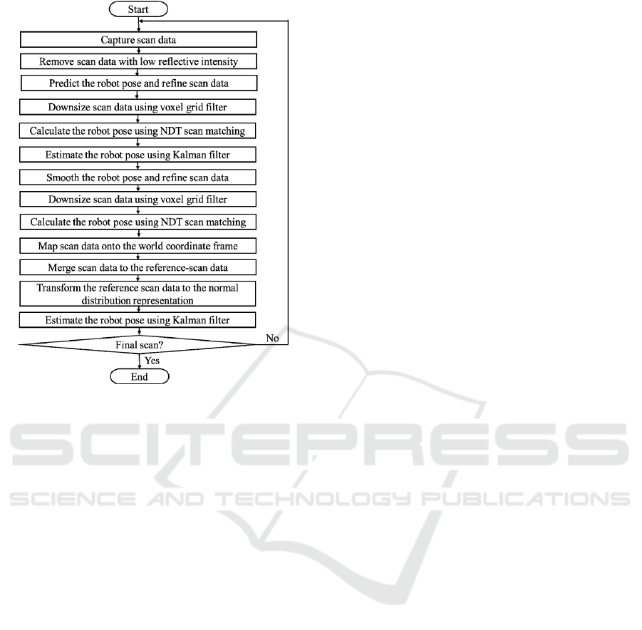
Figure 4: Process of distortion correction in scan data.
can be obtained. We denote the state prediction
related to the robot’s pose,
),,,,,(
ψ
θ
φ
zyx
, as
)1/,1()1/,1(
ˆ
ˆ
−−−− ∈ tjttjt ξX
.
Using Eq. (1), the scan data obtained at
τ
Δ
τ
jt +− )1(
,
),1( jt
bi
−p
where i = 1, 2, …n, can be
transformed to
)1/,1( −− tjt
i
p
as follows:
=
−
−−
−−
1
)
ˆ
(
1
),1(
)1/,1(
)1/,1( jt
bi
tjt
tjt
i
p
XΤ
p
(6)
Using the state prediction,
)1/(
ˆ
−ttX
=
)1/180,1(
ˆ
−− ttX
, the scan data,
)1/,1( −− tjt
i
p
, is re-
transformed into the scan data in
b
Σ
at
τ
t
=
τ
Δ
τ
180)1( +−t
as follows:
=
−−
−
−−
1
)
ˆ
(
1
)1/,1(
1
)1/180,1(
)(
*
tjt
i
tt
t
bi
p
X
p
Τ
(7)
To calculate the robot’s pose,
)(t
NDT
z
, NDT scan
matching is performed using scan data,
{
}
)(
*
)(
*
2
)(
*
1
)(
*
,,, t
bn
t
b
t
b
t
b
pppP =
, as the new input scan.
Based on Eqs. (3) and (4), the Kalman estimation
algorithm then gives a state estimate,
)/(
ˆ
ttξ
, and its
associated error covariance,
)/( ttΓ
, as follows:
−=
−+=
−−−−
−−−−
)1/180,1()()1/180,1()/(
)1/180,1)()()1/180,1()/(
}(
ˆ
{
ˆˆ
ttttttt
ttt
NDT
ttttt
HΓKΓΓ
ξHzKξξ
(8)
where
)(
1
)1/180,1()( t
T
ttt
−
−−= SHΓK
and
=)(tS
RHHΓ −−−
T
tt )1/180,1(
. R is the covariance matrix of
NDT
z
Δ
.
Next, we correct the distortion in the scan data
obtained at
τ
Δ
τ
jt +− )1(
. The Kalman smoothing
algorithm gives state-smoothed data at
τ
Δ
τ
jt +− )1(
as follows:
−+
=
−+
=
−
−+−+−
−−−
−+−+−
−−−
)(
1
)1/1,1()/1,1()(
)1/,1()/,1(
)1/1,1()/1,1()(
)1/,1()/,1(
}{
}
ˆˆ
{
ˆˆ
ttjttjtt
tjttjt
tjttjtt
tjttjt
CΓΓC
ΓΓ
ξξC
ξξ
(9)
where
1
)1/1,1(),1()1/,1()(
−
−+−−−−
= tjt
T
jttjtt ΓFΓC
.
It should be noted that, since a state estimate
cannot be obtained at
τ
Δ
τ
jt +− )1(
, Eq. (9) uses a
state prediction.
Therefore, the scan data obtained at
τ
Δ
τ
jt +− )1(
,
),1( jt
bi
−p
, can be transformed to
),1( jt
i
−p
using
=
−
−
−
1
)
ˆ
(
1
),1(
)/,1(
)/,1( jt
bi
tjt
tjt
i
p
X
p
Τ
(10)
and subsequently re-transformed to obtain the scan
data in
b
Σ
at
τ
t
using the following equation:
=
−
−
1
)
ˆ
(
1
)/,1(
1
)/(
)(
tjt
i
tt
t
bi
p
X
p
Τ
(11)
where
)/(
ˆ
ttX is the robot’s pose estimated according
to Eq. (8).
To calculate the robot’s pose,
)(t
NDT
z
, NDT scan
matching is conducted based on the distortion-
corrected scan data,
{}
)()(
2
)(
1
)( ,,, t
bn
t
b
t
b
t
b
pppP =
, as
the new input scan. Then, Eq. (8) is used to
determine
)/(
ˆ
ttX , and Eq. (1) is used to map the new
input scan onto
W
Σ
.
5 EXPERIMENTAL RESULTS
The robot turned at a T-junction on a road, as shown
in Fig. 5. The maximum linear and turning velocities
ICINCO 2017 - 14th International Conference on Informatics in Control, Automation and Robotics
332
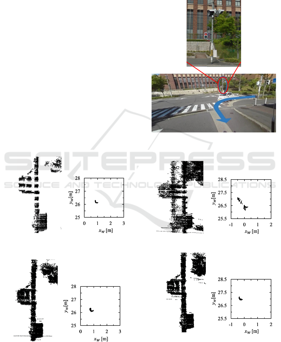
were 11 m/s and 22°/s, respectively. Scan data was
captured in 100 scans (10 s), and the distortion-
correction method was evaluated by mapping a
signal light onto the world coordinate frame,
W
Σ
.
Figure 6 shows the mapping result for the signal
light based on scan data captured by the static laser
scanner. The right figure in Fig. 6 shows the laser
measurements for the pole part of the signal light
(diameter 0.22 m); the mapping result of the signal
light was plotted on the horizontal plane (
x
w
-y
w
plane) in
W
Σ
.
Figure 7 shows the mapping result when the
distortion in the scan data is not corrected. The
robot’s pose was estimated every 0.1 s by NDT scan
matching, and mapping was conducted using scan
data without distortion correction. The scan data is
widely spread sideways and one signal light is
recognized as two signal lights.
Figure 8 shows the mapping result obtained by
the proposed method: distortion correction of the
scan data using the Kalman filter. For comparison
purposes, the distortion in the scan data was also
corrected using a linear extrapolation and
interpolation method, where the extrapolation and
interpolation algorithms correspond to the Kalman
Figure 6: Mapping result of the signal light when the robot
stops.
Figure 8: Mapping result obtained by the proposed
method.
prediction and smoothing algorithms, respectively,
used in the proposed method. The mapping result
obtained by the conventional linear extrapolation
and interpolation method is shown in Fig. 9.
Figure 5: Photo of the environment and signal light used
for an experiment.
Figure 7: Mapping result without distortion correction.
Figure 9: Mapping result obtained by the linear
extrapolation and interpolation method.
Distortion Correction of Laser Scan Data from In-vehicle Laser Scanner based on Kalman Filter and NDT Scan Matching
333

It is clear from Figs. 6–9 that the distortion
correction of the laser-scan data provides a better
mapping result.
The laser-mapping position obtained using the
Kalman filter (the right figure in Fig. 8) is closer to
the actual position shown in Fig. 6, compared with
that obtained using the linear extrapolation and
interpolation method (the right figure in Fig. 9). This
indicates that the mapping performance of the
proposed method is superior to that of the
conventional linear extrapolation and interpolation
method.
6 CONCLUSIONS
In this paper, we presented a distortion-correction
method for laser-scan data obtained from in-vehicle
multilayer laser scanner. The method was achieved
by Kalman prediction, estimation, and smoothing of
the robot’s pose data using NDT scan matching.
Experimental results of mapping a signal light in a
road environment showed the effectiveness of the
proposed method.
Future research will aim at evaluating the
performance of SLAM and moving-object tracking
systems using scan data where the distortion is
corrected using the proposed method.
ACKNOWLEDGEMENTS
This study was partially supported by the Scientific
Grants #26420213, the Japan Society for the
Promotion of Science (JSPS) and the MEXT-
Supported Program for the Strategic Research
Foundation at Private Universities, 2014–2018,
Ministry of Education, Culture, Sports, Science and
Technology, Japan.
REFERENCES
Besl, P. J. and Mckay, N. D., 1992, A Method of
Registration of 3-D Shapes, In IEEE Transactions on
Pattern Analysis and Machine Intelligence, Vol. 14,
No. 2, pp. 239–256.
Biber, P., and Strasser, W., 2003, The Normal Distributions
Transform: A New Approach to Laser Scan Matching,
In Proceedings of IEEE/RSJ International Conference
on Intelligent Robots and Systems (IROS 2003), pp.
2743–2748.
Brenneke, C., Wulf, O., and Wagner, B., 2003, Using 3D
Laser Range Data for SLAM in Outdoor
Environments, In Proceedings of IEEE/RSJ
International Conference on Intelligent Robots and
Systems (IROS 2003), pp. 188–193.
Cadena, C., Carlone, L., and Carrillo, H., et al., 2016, Past,
Present, and Future of Simultaneous Localization and
Mapping: towards the Robust-perception Age, In IEEE
Transactions on Robotics, Vol. 32, No. 6, pp 1309–
1332.
Hess, W., Kohler, D., Rapp, H., and Andor, D., 2016, Real-
Time Loop Closure in 2D Lidar SLAM, In
Proceedings of 2016 IEEE International Conference
on Robotics and Automation (ICRA2016), pp. 1271–
1278.
Hong, S., Ko, H. and Kim, J., 2010, VICP: Velocity
Updating Iterative Closest Point Algorithm, In
Proceedings of 2010 IEEE International Conference
on Robotics and Automation (ICRA 2010), pp. 1893–
1898.
Kanaki, S., Murabayashi, R., and Fujishita, K., et al., 2016,
Cooperative Moving-object Tracking with Multiple
Mobile Sensor Nodes -Size and Posture Estimation of
Moving Objects using In-vehicle Multilayer Laser
Scanner-, In Proceedings of 2016 IEEE Int. Conf. on
Industrial Technology (ICIT 2016), pp. 59–64.
Mertz, C., Navarro-Serment, L., E., et al., 2013, Moving
Object Detection with Laser Scanners, In Journal of
Field Robotics, Vol.30, pp. 17–43.
Moosmann, F. and Stiller, C., 2011, Velodyne SLAM, In
Proceedings of IEEE Intelligent Vehicles Symposium
(IV2011), pp. 393–398.
Mukhtar, A., Xia, L., and Tang, T. B., 2015, Vehicle
Detection Techniques for Collision Avoidance
Systems: A Review, In IEEE Transactions on
Intelligent Transportation Systems, Vol. 16, No. 5,
pp.2318–2338.
Munaro, M., Basso, F., and Menegatti, E., 2012, Tracking
People within Groups with RGB-D Data, In
Proceedings of IEEE/RSJ International Conference on
Intelligent Robots and Systems (IROS 2012), pp.
2101–2107.
Rusu, R. B., and Cousins, S., 2011, 3D is here: Point
Cloud Library (PCL), In Proceedings of 2011 IEEE
International Conference on Robotics and Automation
(ICRA 2011).
Yokoyama, H., Date, H., Kanai, S., and Takeda, H., 2013,
Detection and Classification of Pole-like Objects from
Mobile Laser Scanning Data of Urban Environments,
In International Journal of CAD/CAM, Vol. 13, No. 2,
pp. 31–40.
Zhang, J. and Singh, A., 2014, LOAM: Lidar Odometry
and Mapping in Real-time, In Proceedings of
Robotics: Science and Systems.
ICINCO 2017 - 14th International Conference on Informatics in Control, Automation and Robotics
334
