
Hybrid Software Defined Networking Controller
Kosala Perera, Udesh Gunarathne, Binal Chathuranga, Chamika Ramanayake and Ajith Pasqual
Department of Electronic and Telecommunication Engineering, University of Moratuwa, Kelaniya, Sri Lanka
Keywords:
Software Defined Networking, Controller, Hybrid, FPGA, Bottlenecks.
Abstract:
There exists some common bottlenecks among the many available Software Defined Networking (SDN) con-
trollers. Of these, the current analysis uses the Floodlight software controller to identify bottlenecks. The
analysis has implemented these bottlenecks in a Field Programmable Gate Array (FPGA) in order to assess
its feasibility. Thereafter, a Hybrid SDN controller has been developed. Generally Hybrid SDN refers to a
networking approach where traditional networking and SDN protocols are used and operated in the same envi-
ronment. Hybrid in this paper context refers to a controller which is developed both on software and hardware
platforms in order to achieve a higher scalability which is a current issue existing in software controller, and
thereby overcoming the identified bottlenecks. The analysis has offloaded computational intensive models
to an FPGA and tested for performance. These performance figures have then been compared against the
performance figures as of a stand-alone software controller.
1 INTRODUCTION
It is no doubt that the field of computing has been
growing exponentially through the last three decades.
However there is doubt whether the field of network-
ing has also witnessed the same growth. With time,
traditional networking has become more complex,
closed and proprietary (Kreutz et al., 2015). These
limitations have caused numerous complexities re-
lated to single data centers, interconnected data cen-
ters, cloud computing as well as for the Internet which
is growing at a high speed. Some of the major issues
with current networking architecture are difficulties in
optimization, capital expenditure, and difficulties in
customization. If we have an abstract view of the net-
work, we see that the network is built using numerous
routers, and switches that operate on numerous pro-
tocols. Thus in the current context, this results in an
inability to offer customized and optimized network
solutions to customers.
1.1 Software Defined Networking
SDN architecture comprises of three main compo-
nents namely, Data plane, Controller plane and Appli-
cation layer (Wha, 2017). Controller plane is consid-
ered as the brain of the architecture as it is the central
system that makes decisions. Many vendors have in-
troduced a number of controllers and at present there
is a significant majority of horizontal development in
terms of the SDN controller.
2 PROBLEM STATEMENT
In traditional IP networks, the distributed control and
transport network protocols flow inside the routers
with switches allowing information travel in the form
of digital packets around the network. Using low level
and often vendor specific commands, network oper-
ators need to configure each individual network de-
vice separately due to the desired high level network
policies. Furthermore, in the IP networks, the con-
trol plane and the data plane are inserted inside the
networking devices, shrinking flexibility and hinder-
ing innovation and evolution of the networking infras-
tructure. In addition to the configuration complexity,
current networks are made more complex as they have
to endure the dynamics of faults and adapt to load
changes.
SDN is an emerging networking architecture
which gives opportunity to change the limitations of
current network infrastructure, making it ideal for
the high bandwidth and ideal for the dynamic na-
ture of todays applications. SDN is considered as
a suitable solution for dynamic provisioning of net-
work resources. SDN provides open interfaces that
enable the development of software that can control
Perera, K., Gunarathne, U., Chathuranga, B., Ramanayake, C. and Pasqual, A.
Hybrid Software Defined Networking Controller.
DOI: 10.5220/0006423800770084
In Proceedings of the 14th International Joint Conference on e-Business and Telecommunications (ICETE 2017) - Volume 1: DCNET, pages 77-84
ISBN: 978-989-758-256-1
Copyright © 2017 by SCITEPRESS – Science and Technology Publications, Lda. All rights reserved
77

the connectivity of network resources and the flow of
network traffic. The separation of the control plane
and the data plane can be attained by means of a
well defined programming interface like Openflow
between the switches and the SDN controller. There
are many unique features in SDN such as visibility,
programmability, openness and virtualizability.
SDN controller can be considered as the brain of
the SDN architecture. However, there are some bot-
tlenecks in current SDN controllers such as the inabil-
ity of current SDN controllers to handle a large num-
ber of packets when the network scales up, inability to
operate in high speed networks due to higher traffic,
difficulties in bandwidth allocation and to cope with
the dynamic nature of the network(Akyildiz et al.,
2016). Many SDN controllers are fully software
based controllers. Performance of SDN controllers
is are degrading in high speed networks such as core
networks of service providers due to the lack of CPU
processing power. There is some horizontal integra-
tion such as physically distributed controllers, hierar-
chical controllers and multi-thread controllers. How-
ever there is no well recognized vertical integration in
the current field. Thus, as a solution to this situation,
this analysis considers the introduction of hardware
accelerated SDN controller functions in FPGA.
3 RELATED WORK
Software Defined Networking is an emerging net-
working architecture attempting to mitigate the bot-
tlenecks in the traditional routing and switching net-
work system. However the SDN architecture also
has to face many challenges which have to be over-
come in order to use the SDN concept in large scale
networks. The SDN architecture comprises of three
main components which are Data plane, Controller
plane and Application plane among which the con-
trol plane has the major responsibility in the design.
Hence most of the research is focused onto acceler-
ating the SDN controller plane using different tech-
niques (Katov et al., 2015). SDN controller is the
central nervous system for the SDN as it manages
all the network devices in data plane and services
for the applications in application plane. There are
many researches on analyzing and comparing indus-
trys mainstream SDN controllers such as Floodlight,
POX and OpenDaylight, in order to address the bot-
tlenecks (Caba and Soler, 2015). Several controllers
have been introduced at present but all of them are
in line of a horizontal development(Martinello et al.,
2014). I.e. optimization of controller aspects or dif-
ferent architectures models are introduced at a soft-
ware level. Furthermore the implementation of con-
trol plane on hardware such as Graphical Processing
Units (GPUs) or FPGA has been carried on by several
other research groups.
3.1 A Modularized Carrier-grade SDN
Controller According to the
Characteristics of Carrier-grade
Networks
The modularized carrier-grade SDN controller (Wang
et al., 2014) is a research carried out to resolve the
problem of controlling large-scale networks of carrier
by utilizing a modularized SDN architecture. In order
to achieve flexibility, scalability and stability, the core
modules which are the reason for limiting the con-
troller performance are designed to meet the carriers
need. The research is focused on horizontal devel-
opment of the SDN controller, in which they use new
methods such as using new algorithms, static memory
allocation, multi-threads technique and stick-package
processing to improve the performance of the con-
troller. Three threads are created by the system such
as receiving thread, processing thread and sending
thread to improve the performance of the controller.
Memory for switch is allocated statically by controller
to improve the connecting efficiency of controller and
switches. Stick package processing is introduced to
bind several openflow packets into one TCP packet to
improve performance when the controller receives too
many packets in a short time. That means a cluster is
made up of controllers and communication between
controllers using east west interfaces. This method
can improve the reliability and availability because
even though a single controller is down the other con-
trollers in the cluster can handle the traffic.
3.2 A GPU based SDN Controller
A GPU -SDN controller (Renart et al., 2015) has been
implemented with the goal of mitigating the scalabil-
ity problem by offloading all the packet inspection
and creation to the GPU. Due to the high computa-
tional capabilities GPUs are capable of pattern match-
ing, network coding, IP table lookups and cryptogra-
phy in relation to network workloads. This vertical
development of a SDN controller has paved the way
to handle a number of network packet flows per sec-
ond thus enabling the controller to handle more num-
ber of switches. In the proposed architecture the CPU
threads are divided into two sets, which are producer
threads and consumer threads. The producer threads
fetches and classifies the packets and stores them to
DCNET 2017 - 8th International Conference on Data Communication Networking
78
be inspected by GPU. Then GPU process the packet
and save into a output memory. At the final step the
consumer threads fetch the packets from output mem-
ory and send them back to their resources.
GPU controller can handle more packet flows than
a regular controller. It also maximized the number of
simultaneous switches a controller can handle. The
major bottleneck of this proposed design is the trans-
fer time for the batch processed packets. The transfer
time has been increased because the packets are pro-
cessed as batches to reduce processing overhead. Fur-
thermore due to the batch transferring from the CPU
memory to GPU memory, the PCI-e and the CPU
memory bandwidth also have become bottlenecks. In
addition to these, the advantage over CPU for GPU is
suppressed because the CPU cannot keep up with the
GPU processing.
4 IDENTIFICATION OF
BOTTLENECKS IN THE
SOFTWARE CONTROLLER
Floodlight source code was edited in order to an-
alyze the time taken by each module to process
a PACKET_IN message.(Ope, 2017) Mininet emula-
tor(Min, 2017) was used to generate different topolo-
gies in the test environment. Topologies consisted
with nodes ranging from 2- 256 nodes. Hence an av-
erage processing time was able to be obtained. For-
warding (Routing), Link Discovery, Device Manager,
Firewall, Topology modules were tested to identify
the bottlenecks in the Floodlight controller.
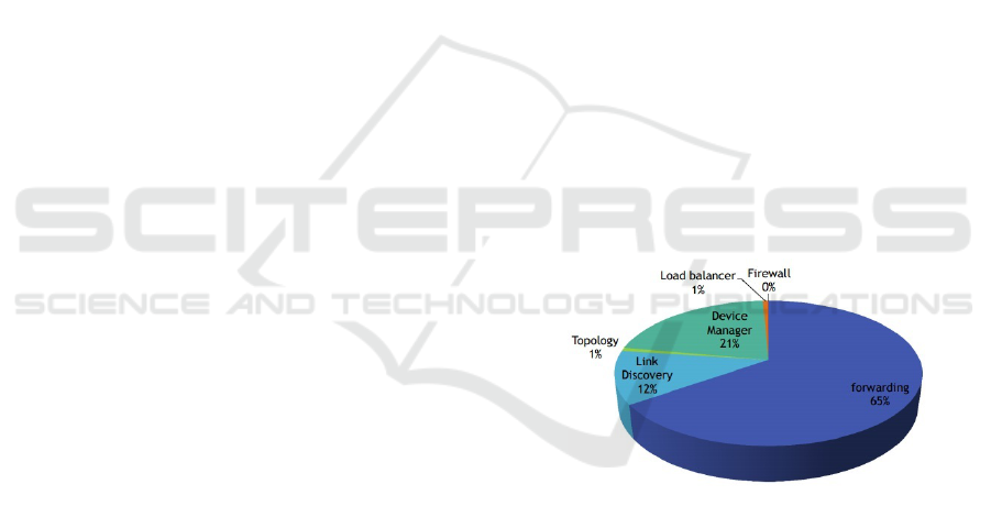
4.1 Forwarding Module
Forwarding module is responsible for deciding when
there is a flow table miss. The routing will comprise
of sub-modules which are computational extensive.
Thus it will consume the highest amount of process-
ing time.
4.2 Device Manager Module
Device Manager Module extracts the information
from the PACKET_IN and classifies the device by
MAC address and VLAN. The Device manager will
also learn about IP addresses. In summary, Device
Manager will track devices as they move around a
network and define the destination device for a new
flow.
4.3 Link Discovery Module
Link discovery module is responsible for maintaining
the status of the links and the nodes of the network.
The total processing time, number of LLDP (Link
Layer Discovery Protocol) packets generated is expo-
nentially increased when number of nodes increases.
LLDP
in
= 2 ∗L (1)
LLDP
out
=
n
∑
k=0
p
i
(2)
where, L = number of links
n = number of nodes
p
i
= number of ports in the i
th
node
4.4 Load Balancer Module
This module is implemented to share the load be-
tween the links. This module is not required for core
functionality.
4.5 Firewall Module
This module is implemented with the Access Control
List(Cis, 2017) rules. According to the rule set, it will
decide whether to allow the traffic or not.
Figure 1: Module processing time as a percentage.
It is evident from Figure 1 that forwarding module
consumes a majority of time following other modules.
The next objective was implementing these modules
on an FPGA in order to hardware accelerate and re-
duce the processing overhead on the Floodlight con-
troller.
5 SYSTEM ARCHITECTURE
Existing software based SDN controllers are unable
to handle large number of flows thereby making
SDN controller the bottleneck of this architecture. If
the controller can process one PACKET_IN request in
Hybrid Software Defined Networking Controller
79

lesser time, it will increase the number of packets pro-
cessed in a unit time. Critical parts of the SDN con-
troller can be hardware accelerated. The current anal-
ysis uses FPGA to hardware accelerate the bottleneck
functions of the controller which were identified dur-
ing the first phase of the project. This hardware ac-
celerated controller consists of CPU processing and
FPGA processing, which makes it a hybrid. Commu-
nication between FPGA and CPU achieved through
PCIe.
5.1 Reusable Integration Framework
for FPGA Accelerators (RIFFA)
RIFFA(Arc, 2017) is an open-source platform used
for interfacing and communicating data between a
host CPU and an FPGA via a PCI Express bus. Nec-
essary data that needs to be offloaded to the FPGA is
sent and the results are received via RIFFA. A chan-
nel length of 128 bits was used for the communication
between the CPU and FPGA. Since the data transfer
rate can impose a bottleneck, minimal data transfer is
maintained to achieve optimization.
5.2 CPU
In the Floodlight SDN controller the forwarding mod-
ule and the device manager module takes more time
than others and thus the CPU processing time can-
not be further reduced. Therefore the proposed de-
sign transfers the basic functionality that limits the
performance of Floodlight to the FPGA. In order to
transfer the functionality to the hardware aspect, three
modules are implemented in the FPGA. These imple-
mented modules obtain necessary data from the CPU
side through RIFFA. The obtained data include initial
topology data, link details, MAC address data, and
route request data.
5.2.1 The Initial Topology Data
The initial topology data contains the cost for each
link. These data are fed into FPGA at the beginning.
5.2.2 Details of Links
In the link discovery manager module, the floodlight
controller detects the links between the switches and
uses those data to update the FPGA about the switch
to switch connections.
5.2.3 MAC Address Data
In the forwarding module of the floodlight controller,
if a new mac address is detected then it is saved and
sent to the FPGA along with connected switches’ dat-
apath id and port. These details are used to build the
complete topology in the FPGA and will later be used
to calculate the routes.
5.2.4 Route Request Data
In addition to MAC address data, the forwarding mod-
ule of the floodlight controller is used to request the
route from FPGA for each flow table miss. This is
done by sending the source and destination mac ad-
dresses to the FPGA.
In each of the modules mentioned above, the
floodlight’s functionality is bypassed and replaced by
the relevant FPGA functions. The CPU-FPGA com-
munication is handled by RIFFA and hence it is done
through PCI-e. Except for the route request data, the
other three types only conduct simplex communica-
tion between FPGA and CPU. In the route request
data both the fpga.send and fpga.receive func-
tions are used to enable half duplex communications
between two sides.
5.3 FPGA
The analysis uses open source Floodlight controller
for the CPU side. During phase one, the following
bottleneck functions were identified. 1. Forwarding
module takes the most amount of processing time.
2. Device manager also takes a significant portion of
processing time to find the device attachment points.
Therefore essential parts of these modules have been
implemented in FPGA. Figure 2.Block diagram of
FPGA architecture shows the architecture of FPGA
implementation. Following subsections describes the
three main modules were implemented in theFPGA,
1. Idevice 2. Dijkstra 3. Port Map and 4. Interconnec-
tion shown in Figure 2.
5.3.1 Mac Cache
Idevice keeps track of the connected device to the
network. They can be either a single host or net-
work. Once a PACKET_IN comes to the SDN con-
troller it has to find what the device attachment point
to network is. This requires the decoding of open-
flow packet and extracting MAC address or IP ad-
dress and locating all connected points. Even though
it is possible to find attachment points to the network
by IP address, in this architecture the current analy-
sis uses MAC address of PACKET_IN to find attach-
ment points, in an attempt of simplifying the design.
Operation of the Idevice FPGA module can be de-
scribed as below. Once a SDN controller detects that
a new device or new network is connected, it sends
DCNET 2017 - 8th International Conference on Data Communication Networking
80

MAC address of the device and Datapath Id, OF-
port number to the FPGA and FPGA stores this data
in an Array. When PACKET_IN comes to SDN con-
troller, it sends source and destination MAC addresses
to FPGA. Next, FPGA finds the device attachment
points through parallel search of the Array. Using this
method the complexity of finding Device attachment
point reduces to O(1).
5.3.2 Dijkstra
Dijkstra algorithm finds the shortest distance between
source and destination of a network. Dijkstra is
widely used in many networking protocols such as
Open shortest path first (OSPF). Dijkstra algorithm
exists in many forms. Optimized Dijkstra algorithm
runs with the time complexity of
logO(|E| + |V |log|V |) (3)
where,
E = number of edges of the network
V = number of nodes of the network.
In FPGA implementation, time complexity of
O(V) has been achieved. Operation of the module
can be described as follows. FPGA uses two mem-
ories, one for store the network topology and one for
store intermediate costs between source and its pre-
decessor. For example if i
th
memory location is the
source and its the currently working node, the system
has been designed to calculate cost for the whole net-
work simultaneously (parallel computation) from i
th
node. It then chooses the minimum cost node as the
currently working node (combinational circuit calcu-
lates the minimum cost), and repeats the above steps
to a new currently working node. This iterates until
it reaches the destination. These details are stored in
an intermediate cost Matrix. Since iteration are lin-
ear, time complexity is O(n). Next part of the design
is to formulate complete route. Backward calculation
from destination memory location to source memory
location of intermediate matrix will provide the route
in which time complexity is O(n). Hence total time
complexity will be O(n).
5.3.3 Port Map
Complete routing information output from the Flood-
light controller consists of Datapath ID and relevant
OFport numbers. Dijkstra module only calculates
path in terms of Datapath Id and gives an intermediate
result. Port Map module takes this intermediate result
and assigns OFport by taking link information of the
network. Basic operation of the module can be de-
scribed as below. When controller detects a new link
it sends a signal of the newly learned information to
the FPGA through Riffa. This information is stored
in FPGA. Once the Dijkstra module is completed,
its result is taken to the Port Map module with two
adjacent Datapath IDs from intermediate route being
taken. Considering these two Datapath IDs, Port Map
module conducts a parallel search to find the link in-
formation in between these Datapath IDs. This calcu-
lation is repeated until the total length of route from
Dijkstra module is reached.
5.4 Interconnection
Each of these FGPA modules can be connected
to Floodlight controller directly which bypasses the
same functionality of the controller. During the pro-
cessing of PACKET_IN these three modules are called,
and since there are three modules six Riffa transmit
and receive operations occur. Riffa interface takes
considerable amount of time compared to the process-
ing time of the modules in FPGA. Therefore Archi-
tecture was built in such a way that three modules are
interconnected through FPGA. Idevice module takes
MAC addresses as inputs and Port Map module gives
complete information of the route. This mechanism
reduces required communications to two Riffa com-
munications, send and receive.
In order to control the three modules and send
control signal to each module state machine has de-
signed. Each module has its reads and writes oper-
ations and reset signals. State machine trigger them
according to the CPU side commands. In order to
control the three modules and send control signals to
each module, state machine has been designed. Each
module has its reads and writes operations and reset
signals. State machine trigger them according to the
CPU side commands. Processing chain of this archi-
tecture to process an openflow PACKET_IN can be ex-
plained as below. Source and destination MAC ad-
dress of openflow PACKET_IN are sent to FPGA from
Floodlight controller (floodlight controllers code has
been changed to be compatible with this operation).
Idevice module takes these MAC address and con-
ducts parallel search through sorted devices. It then
outputs the source Datapath Id, destination Datapath
Id, source OFport, and destination OFport. Source
Datapath Id with the Destination Datapath Id being
sent to Dijkstra Module and source port and desti-
nation port being sent to Port Map module. After
completion of Idevice module, Dijkstra module will
be triggered. Dijkstra module calculates the shortest
path between a given source and destination Datapath
Id. The output will be a sequence of Datapath Ids.
Completion of Dijkstra module enables the Port Map
module. The Port Map module searches through its
Hybrid Software Defined Networking Controller
81
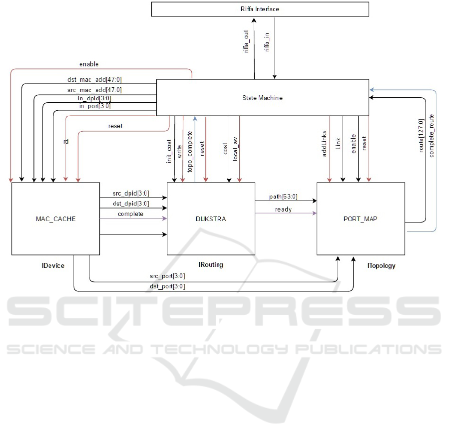
Figure 2: Block diagram of FPGA architecture.
links for adjacent Datapath Ids and output the com-
plete route which is the sequence of links between
source and the destination. State machine sends re-
sult back to floodlight controller.
5.5 Parallel Flow Implementation
Parallel flow implementation is a software based im-
provement for the floodlight controller. In order
to explain this concept, a network with 4 openflow
switches (S1, S2, S3 and S4) connected linearly with
each other can be considered. Route request from host
connected in S1 to host connected in S4 creates flow
table miss in S1. S1 sends the PACKET_IN to con-
troller. Controller processes the packet and if con-
troller sends a PACKET_OUT only for S1 and thereafter
it creates flow table miss in S2 which will generate
another PACKET_IN. Likewise a total of 8 openflow
packets (PACKET_INs and PACKET_OUTs) are gener-
ated. Another drawback in this process is the time
taken between each switch and controller. Proposed
method improves this by parallel flow implementa-
tion. When processing the PACKET_IN generated
from the S1 switch, the controller calculates the whole
path from source to destination. Controller then sends
FLOWMOD packets to all the affected switches, in this
case S1, S2, S3 and S4. This will reduce the number
of packets generated (only 5 packets in the example
network) between data plane and control plane. Only
S1 will wait for controllers reply. Other switches (in
this example S2, S3 and S4) will have flow table entry
by the time data plane packet arrives to each switch.
Floodlight has adapted a similar approach but
it sends FLOWMOD packets starting from the destina-
tion. This means that it first installs the flow entry
in S4, S3, S2 and S1 respectively. Drawback in this
method is that S1 has to wait until controller sends
FLOWMODs to all other switches but this approach en-
sures that no PACKET_INs will generate from interme-
diate switches.
In parallel flow implementation, FLOWMOD starts
from source side. Which means FLOWMOD packet will
go to S1 and then to S2, S3, S4 respectively. This
method reduces the time taken to start the route in
data plane. There might be a possibility of generating
PACKET_IN from intermediate switch if controller is
unable to send FLOWMOD in time. The current analysis
captures the links between data plane and controller
plane to check if there are any such intermediate
packet generations. Wireshark packet capture shows
that there is no intermediate packet generation in par-
allel flow implementation. Even though FLOWMODs
DCNET 2017 - 8th International Conference on Data Communication Networking
82
are not installed to switches parallel, this approach
achieves the same performance level as when flows
installed in parallel.
6 IMPLEMENTATION
For the implementation of the hybrid SDN controller,
a Xilinx Virtex-7 FPGA VC707(Xil, 2017) board has
been used. Floodlight controller which is using Open-
Flow 1.3(Ope, 2017) was installed on a Hewlett-
Packard Z420 Workstation(HPZ, 2017). Riffa pro-
vides two options of having the data width of either
64 bits or128 bits. 128 bits has been chosen in this
analysis as it allows to reduce the number of commu-
nications between the CPU and FPGA.
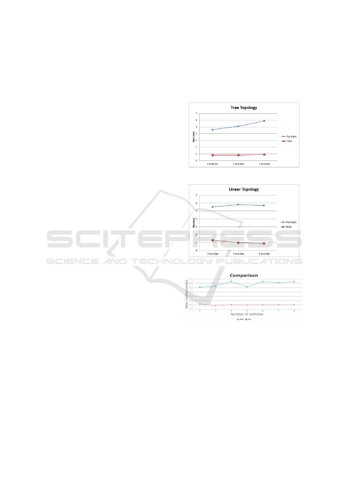
7 TESTING RESULTS
Testing is done by measuring the time taken to cal-
culate routes by floodlight controller and FPGA mod-
ule respectively. In the graphs the blue colored line
shows the time taken for calculating a route by flood-
light controller and red colored line shows the time
taken by FPGA implemented module for the same, in-
cluding RIFFA communication time. Figure 3 shows
the testing results for custom topologies of 2 switch,
3 switch, 4 switch, 5 switch, 6 switch, 7 switch and
8 switch networks. As shown in the figure there is
a 5-6 times performance improvement in the hybrid
SDN controller than that of floodlight controller. Fig-
ure 4 shows the testing results for tree topology and
time was measured for 3 switch, 5 switch and 7 switch
networks. Furthermore figure 5 shows the testing re-
sults for linear topology and time was measured for
2 switch, 4 switch and 8 switch networks. Similar to
custom topologies, both tree and linear topologies il-
lustrates a 4-6 times improvement in hybrid controller
than that of the floodlight controller. Therefore the
test data verifies that the routing in FPGA is more ef-
ficient than routing in software controller.
If we compare the results with the similar ap-
proaches to improve performance of the SDN con-
troller, the GPU based controller(Renart et al., 2015)
is the other implementation based on a hybrid con-
cept. In the GPU based controller, it uses batch pro-
cessing of numerous packets in order to lower per-
packet processing overhead. However, it increases the
latency of every single packet. In FPGA based hybrid
controller there is no such additional latency intro-
duced and the workload is shared between FPGA and
CPU because not like in GPU based controller, the
FPGA module processes only the new route requests.
Furthermore in contrast to the GPU based controller,
only the necessary details are communicated between
FPGA and CPU to reduce the overhead. The compar-
ison shows that the further improvements in FPGA
based hybrid controller can be immensely helpful for
a better SDN controller.
Figure 3: Routing time comparison for tree topology.
Figure 4: Routing time comparison for linear topology.
Figure 5: Routing time comparison for custom topology.
8 CONCLUSION
The SDN controller is considered as the brain of the
network. It takes all the decisions on behalf of the
SDN network thus demanding for a high processing
power. At times it has proven that the stand-alone
CPU power is not adequate and it leads to creation of
bottlenecks. This hinders the overall SDN controller
performance. Our preliminary results show that these
bottlenecks can be overcome successfully with the
implementation of a hybrid controller where FPGA
Hybrid Software Defined Networking Controller
83

process the complex tasks that require high process-
ing power.
The current study presents a SDN controller from
a vertical integration perspective as a solution to these
bottlenecks. Hybrid SDN controller was able to scale
up the SDN network without causing the process-
ing time to rise exponentially. With the parallel flow
implementation, the hybrid SDN controller was able
transfer flows to data plane devices efficiently.
In addition to the methods described under sec-
tion 9 can be implemented to optimize the hybrid con-
troller further.
9 FUTURE DEVELOPMENTS
We found out that another instance where a consider-
able amount of traffic generated between data plane
and controller plane is due to the Link Layer Dis-
covery Protocol(Lin, 2017). This happens when the
network scales up. This is due to the generation of
LLDP packets increase. The controller will keep on
generating LLDP packets in order to maintain the net-
work topology. This can cause unwanted processing
power dedicated if the network stays as it is without
failing. But on the other hand some sort of LLDP
is required. We propose a method which allows the
SDN switch to inform the controller if the link is lost.
This method will give some sort of intelligence to the
SDN switches rather than considering them as dumb.
The next improvement in this architecture is par-
allel processing between software and hardware. At
the first stage the current architecture has by-passed
the software functionality to hardware but in the pro-
posed future approaches, the software will do the pro-
cessing functionality if the maximum capacity of the
hardware has been reached. This ensures that none of
the core members in the hybrid controller, software
section and hardware section, is overloaded with pro-
cesses.
REFERENCES
Architecture — riffa: A reusable integration framework for
fpga accelerators. http://riffa.ucsd.edu/node/2. (Ac-
cessed on 03/10/2017).
Cisco ios security configuration guide, release 12.2
- access control lists: Overview and guidelines
[cisco ios software releases 12.2 mainline] - cisco.
http://www.cisco.com/c/en/us/td/docs/ios/12 2/securi
ty/guide/fsecur c/scfacls.html. (Accessed on
03/02/2017).
Hp z420 workstation — 8-core, 2d or 3d graphics
workstation — hp canada. http://www8.hp.com/
ca/en/campaigns/workstations/z420.html. (Accessed
on 03/15/2017).
Link layer discovery protocol - wikipedia. https://en.
wikipedia.org/wiki/Link Layer Discovery Protocol.
Mininet: An instant virtual network on your laptop (or
other pc) - mininet. http://mininet.org/. (Accessed on
03/05/2017).
Openflow - open networking foundation. https://www.open
networking.org/sdn-resources/openflow. (Accessed
on 03/12/2017).
Whats software-defined networking (sdn)?
https://www.sdxcentral.com/sdn/definitions/what-
the-definition-of-software-defined-networking-sdn/.
(Accessed on 01/09/2017).
Xilinx virtex-7 fpga vc707 evaluation kit.
https://www.xilinx.com/products/boards-and-kits/ek-
v7-vc707-g.html. (Accessed on 03/11/2017).
Akyildiz, I. F., Lee, A., Wang, P., Luo, M., and Chou, W.
(2016). Research challenges for traffic engineering in
software defined networks. IEEE Network, 30(3):52–
58.
Caba, C. and Soler, J. (2015). Mitigating sdn controller
performance bottlenecks. In Computer Communica-
tion and Networks (ICCCN), 2015 24th International
Conference on, pages 1–6. IEEE.
Katov, A. N., Mihovska, A., and Prasad, N. R. (2015).
Hybrid sdn architecture for resource consolidation in
mpls networks. In Wireless Telecommunications Sym-
posium (WTS), 2015, pages 1–8. IEEE.
Kreutz, D., Ramos, F. M., Verissimo, P. E., Rothen-
berg, C. E., Azodolmolky, S., and Uhlig, S. (2015).
Software-defined networking: A comprehensive sur-
vey. Proceedings of the IEEE, 103(1):14–76.
Martinello, M., Ribeiro, M. R., de Oliveira, R. E. Z., and
de Angelis Vitoi, R. (2014). Keyflow: a prototype
for evolving sdn toward core network fabrics. IEEE
Network, 28(2):12–19.
Renart, E. G., Zhang, E. Z., and Nath, B. (2015). Towards
a gpu sdn controller. In Networked Systems (Net-
Sys), 2015 International Conference and Workshops
on, pages 1–5. IEEE.
Wang, F., Wang, H., Lei, B., and Ma, W. (2014). A re-
search on high-performance sdn controller. In Cloud
Computing and Big Data (CCBD), 2014 International
Conference on, pages 168–174. IEEE.
DCNET 2017 - 8th International Conference on Data Communication Networking
84
