
SLAM Algorithm by using Global Appearance of Omnidirectional
Images
Yerai Berenguer, Luis Pay
´
a, Adri
´
an Peidr
´
o and Oscar Reinoso
Departamento de Ingenier
´
ıa de Sistemas y Autom
´
atica, Miguel Hern
´
andez University, Spain
Keywords:
SLAM, Global Appearance, Omnidirectional Images, Vision systems, Image description, Loop Closure
Abstract:
This work presents a SLAM algorithm to estimate the position and orientation of a mobile robot while simulta-
neously creating the map of the environment. It uses only visual information provided by a catadioptric system
mounted on the robot formed by a camera pointing towards a convex mirror. It provides the robot with omni-
directional images that contain information with a field of view of 360 degrees around the camera-mirror axis.
Each omnidirectional scene acquired by the robot is described using global appearance descriptors. Thanks to
their compactness, this kind of descriptors permits running the algorithm in real time. The method consists of
three different steps. First, the robot calculates the pose of the robot (location and orientation) and creates a
new node in the map. This map is formed by connected nodes between them. Second, it detects loop closures
between the new node and the nodes of the map. Finally, the map is optimized by using an optimization
algorithm and the detected loop closures. Two different sets of images have been used to test the effectiveness
of the method. They were captured in two real environments, while the robot traversed two paths. The results
of the experiments show the effectiveness of our method.
1 INTRODUCTION
The Simultaneous Localization and Mapping
(SLAM) has been regarded as one of the most impor-
tant technologies in mobile robot research during the
last few years (Munguia et al., 2016; Whelan et al.,
2016). Many of these works are focused on the use
of visual information to carry out SLAM algorithms,
due to the rich information provided by the visual
sensors.
In addition to this, visual sensors can be con-
figured in different ways like conventional cameras,
stereo systems, array of cameras and catadioptric sys-
tems. This last configuration is formed by a single-
viewpoint camera pointing towards a convex mirror
(Nagahara et al., 2007). The resulting image captured
by this last kind of camera contains information on a
field of view of 360 degrees around the camera-mirror
axis. They are named omnidirectional images.
In the field of SLAM, omnidirectional images
have many advantages because they contain informa-
tion with a field of view of 360 degrees around the
mirror axis and the robot does not need to rotate. We
can find many previous works that use omnidirec-
tional images in mapping and localization tasks. For
example, Valiente et al. (Valiente et al., 2014) present
a comparison between two different visual SLAM
methods using omnidirectional images and Garcia et
al. (Garcia-Fidalgo and Ortiz, 2015) make a survey
of vision-based topological mapping and localization
methods.
Traditionally, the developments in mobile robots
using visual sensors are based on the extraction and
description of some landmarks from the scenes, such
as SIFT (Scale-Invariant Feature Transform) (Lowe,
1999) and SURF (Speeded-Up Robust Features) (Bay
et al., 2006) descriptors. This approach presents some
disadvantages: the computational time to calculate
and compare the descriptors is usually high, and it
leads to relatively complex mapping and localization
algorithms. As an advantage, only few positions need
to be stored in the map to make the localization pro-
cess possible.
More recently, some works propose using the
global information to describe the scenes, creating a
unique descriptor per image. These techniques have
demonstrated to be a good option to solve the local-
ization and navigation problems when the movement
of the robot is contained in the floor plane. For ex-
ample, Chang et al. (Chang et al., 2010) presents a
vision-based navigation and localization system using
the gist descriptor, Pay
´
a et al. (Pay
´
a et al., 2010) use
382
Berenguer, Y., Payá, L., Peidró, A. and Reinoso, O.
SLAM Algorithm by using Global Appearance of Omnidirectional Images.
DOI: 10.5220/0006434503820388
In Proceedings of the 14th International Conference on Informatics in Control, Automation and Robotics (ICINCO 2017) - Volume 2, pages 382-388
ISBN: Not Available
Copyright © 2017 by SCITEPRESS – Science and Technology Publications, Lda. All rights reserved

a descriptor based on the Fourier signature in Monte
Carlo localization tasks, and Wu et al. (Wu et al.,
2014) propose an efficient visual loop closure detec-
tion method. In (Pay
´
a et al., 2014), several methods
to obtain global descriptors from panoramic scenes
are analyzed and compared to demonstrate their va-
lidity in map building and localization. The majority
of these global appearance descriptors can be used in
real time because the computational time to calculate
and handle them is low, and they usually lead to more
straightforward mapping and localization algorithms.
Sometimes, the mapping process produces an er-
ror measure in each map position due to the itera-
tive calculation of new poses of the robot. This can
be a big problem in extensive environments when the
robot has to calculate many new poses because the er-
ror is increasing in each iteration. This uncertainty
can be reduced by detecting loop closures and us-
ing optimization algorithms to relocate each previous
pose. This problem is thoroughly studied in this work.
The contribution of this work is the creation of a
method to carry out SLAM tasks by only using vi-
sual information of the environment and global ap-
pearance descriptors. Each omnidirectional scene ac-
quired by the robot is described using global appear-
ance descriptors. The method consists of three differ-
ent steps: calculating the pose of the robot (location
and orientation), detecting loop closures (by compar-
ing global appearance descriptors) and optimizing the
map (by using the G2O optimization algorithm). The
optimization algorithm used in the presented paper is
named G2O and it was presented by K
¨
umerle et al.
(K
¨
ummerle et al., 2011).
The experiments have been carried out with two
different sets of images captured while the robot tra-
versed two real working environments. The first one
has been taken following a rectangular path indoors.
The second one has been captured following a real
path including several rooms in a building.
The remainder of this paper is structured as fol-
lows. Section 2 introduces some preliminary con-
cepts about image description and graph optimization.
Section 3 presents the SLAM algorithm we have im-
plemented to solve the simultaneous localization and
mapping problem. Section 4 describes our databases
used to carry out the experiments and presents the ex-
periments and results. At last, section 5 outlines the
conclusions.
2 PRELIMINARIES
Along the paper, two methods are used to describe
the global appearance of scenes: the Radon transform
and the Histogram of Oriented Gradients (HOG). This
section includes some information on them. Also,
we present the fundamentals of the methods used to
calculate the difference between two images captured
from different locations. At last, we describe the op-
timization algorithm used to recalculate the previous
map positions after detecting loop closures.
2.1 Global Appearance Descriptors
Methods based on the global appearance of the scenes
constitute a robust alternative to methods based on
landmark extraction and description. This is because
global appearance descriptors represent the environ-
ment through high level features that can be inter-
preted and handled easily.
This subsection presents the image descriptors we
have used to describe the omnidirectional images.
Both of them are based on global appearance, with-
out any segmentation or local landmark extraction.
2.1.1 Radon Transform
The Radon transform was described initially in
(Radon, 1917). Previous research demonstrates the
efficacy of this descriptor in shape description and
segmentation such as (Hoang and Tabbone, 2010) and
(Hasegawa and Tabbone, 2011). Hoang et al. (Hoang
and Tabbone, 2010) present a shape descriptor, invari-
ant to geometric transformations, based on the Radon,
Fourier and Mellin transforms, and Hasegawa et al.
(Hasegawa and Tabbone, 2011) describe a shape de-
scriptor combining the histogram of the Radon trans-
form, the logarithmic-scale histogram and the phase-
only correlation. Berenguer et al. (Berenguer et al.,
2015) present a 2D localization method using a global
appearance descriptor based on the Radon transform.
They demonstrate the effectiveness and robustness of
this descriptor.
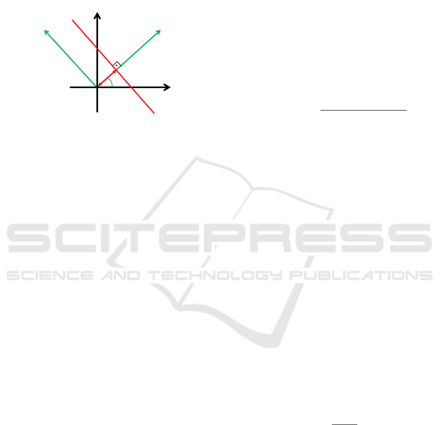
Mathematically, the Radon transform of an image
im(i, j) ∈ R
KxL
along the line c
1
(φ, d) (Figure 1) can
be obtained as:
R {im(i, j)} = λ
f
(φ, d) =
=
Z
R
im(d cos φ − j
0
sinφ, d sin φ + j
0
cosφ) dj
0
(1)
where R is the Radon transform operator. im(i, j) is
the image to transform. λ
f
is the transformed func-
tion, which depends on two new variables: the dis-
tance from the line c
1
to the origin d and the angle
between the x axis and the i
0
axis, φ (Figure 1). j
0
axis
is parallel to the c
1
line.
By considering different values for d and φ in
Equation (1), the transformed function λ
f
(φ, d) will
SLAM Algorithm by using Global Appearance of Omnidirectional Images
383
become a matrix with M rows and N columns. M is
the number of orientations considered (normally cho-
sen to cover the whole circumference), and N is the
number of parallel lines considered at each orienta-
tion (to cover the whole image). The distance between
each pair of consecutive lines is considered constant.
c
1
d
j
i
φ
i’
j’
Figure 1: Line parametrization through the distance origin
d and the angle between the normal line and the i axis, φ.
When the Radon transform is applied to an image,
it calculates the image projections along the specified
directions through a cluster of line integrals along par-
allel lines in this direction. The distance between the
parallel lines is usually one pixel.
2.1.2 Histogram of Oriented Gradients (HOG)
HOG has been used traditionally as a description
method in the field of object detection. It was initially
described by (Dalal and Triggs, 2005). They used it
in people detection tasks. However, there are several
researches in which this description method has been
improved, such as (Zhu et al., 2006), who improve the
accuracy and the computational cost.
The basic implementation consists in dividing the
image in small connected cells and the histogram of
gradient orientations is calculated in each cell. Then,
the descriptor is composed of these histograms ar-
ranged in a single vector.
Fernandez et al. (Fern
´
andez et al., 2016) analyze
this kind of descriptor in outdoor localization tasks.
Furthermore, they make a comparative analysis be-
tween several methods to describe outdoor panoramic
images.
2.2 Phase Only Correlation (POC)
In this subsection we present the method used to com-
pare the Radon transform of two images. It provides a
measurement of difference between the visual appear-
ance of two locations and estimation of the change of
orientation of the robot between these locations.
POC (Phase Only Correlation), proposed in
(Kuglin and Hines, 1975), is an operation made in the
frequency domain that provides a correlation coeffi-
cient between two images (Kobayashi et al., 2004).
In our case we compare two Radon transforms but
this does not affect the POC performance because the
Radon transform can be interpreted as an image. In
general, it permits obtaining both the relative orien-
tation between two different Radon transforms and
a similitude coefficient between them, as shown in
(Berenguer et al., 2015).
The correspondence between two images im
1
(i, j)
and im
2
(i, j) calculated by POC is given by the fol-
lowing equation:
C(i, j) = F
−1
IM
1
(u, v) · IM
∗
2
(u, v)
|
IM
1
(u, v) · IM
∗
2
(u, v)
|
(2)
Where IM
1
is the Fourier transform of the image
1 and IM
∗
2
is the conjugate of the Fourier transform
of the image 2. F
−1
is the inverse Fourier transform
operator.
To estimate the distance between the two images
(im
1
and im
2
) we have used the following expression:
dist(im
1
, im
2
) = 1 − max{C(i, j)} (3)
max{(C(i, j)} is a coefficient that takes values in
the interval [0, 1] and it measures the similitude be-
tween the two images im
1
andim
2
.
This operation is invariant against shifts of the im-
ages along the i and j axes. Furthermore, it is possible
to estimate these shifts ∆
x
and ∆
y
along both axes by:
(∆
x
, ∆
y
) = argmax
(i, j)
{C(i, j)} (4)
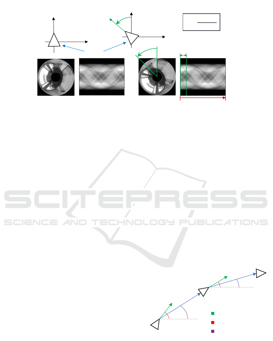
If we compare the Radon transforms of two omni-
directional images using POC, the value ∆
x
is propor-
tional to the relative orientation α of the robot when
capturing the images according to Equation (5). The
Figure 2 shows the Radon transforms of two different
omnidirectional images captured from the same point
(x
w
, y
w
, z
w
) but with different robot orientation with
respect to the z
w
axis, θ (Figure 2).
α =
∆
x
· 2π
N
(5)
This way, POC is able to compare two images in-
dependently on the orientation and it is also able to
estimate this change in orientation.
2.3 Optimization Algorithm: G2O
G2O is an optimization algorithm described in
(K
¨
ummerle et al., 2011). This method was created
for optimizing graph-based nonlinear error functions.
ICINCO 2017 - 14th International Conference on Informatics in Control, Automation and Robotics
384
50 100 150 200 250 300 350
100
200
300
400
500
600
700
800
900
1000
50 100 150 200 250 300 350
100
200
300
400
500
600
700
800
900
1000
⍺
⍺
Robot
1 N
⍺ =
∆
$
· 2𝜋
𝑁
(a)
(b)
y
w
x
w
y
w
x
w
Δx
Figure 2: (a) Omnidirectional image captured from a specific position of a virtual environment and its Radon transform. (b)
Omnidirectional image taken from the same location changing only the robot orientation around the z
w
axis, and its Radon
transform. A change in the robot orientation around the z
w
axis produces a shift in the columns of the Radon transform, ∆x.
In the field of SLAM, the robot has to calculate
its pose when it takes every new image with respect
to the previous poses included in the map. This oper-
ation has an error associated that increments in each
pose calculation, so we need to correct the poses to
decrease this deviation. G2O is able to recalculate
each pose of the map using new pose restrictions. One
of these restrictions can be obtained when loop clo-
sures between one pose of the existing map and the
new pose of the robot occur. Then, G2O relocates
each pose of the map gradually modifying them to
fulfill the loop closure restriction.Then, the new pose
is located the same position than the equivalent pose
stored in the map.
3 SLAM METHOD
In this section, we introduce our visual SLAM ap-
proach. The robot goes through the environment and
captures images from some positions. Every time a
new image arrives, the robot includes a new node in-
side the map. This map is formed by nodes. Then, the
SLAM problem is solved, following these three steps:
First, the robot calculates two descriptors of the
image: the Radon transform and the HOG descriptor;
and stores them in the node. Then, the robot creates
a new node and locates it inside the map calculating
the position and orientation of the new node with re-
spect to the previously added node, and both nodes
are connected. This localization process is carried out
by using only visual information.
Second, the robot checks the existence of possi-
ble loop closures comparing the new scene with the
previous scenes stored in the map.
Finally, the map is optimized by using the G2O al-
gorithm with the loop closures detected. This process
is repeated in each new location.
3.1 Creating the Map
This subsection presents the method proposed to cal-
culate the coordinates of each new node location.
These new poses are estimated by calculating the dis-
tance and the angle between scenes. For each new
node, the robot stores the Radon descriptor and the
HOG descriptor of the new omnidirectional image
taken to do possible the localization of it.
Figure 3 shows a scheme of the mapping process.
It consist of the calculation of the (x
k
, y
k
) coordinates
of each new node. These coordinates are calculated
from the distance and angle between poses.
⍺
1
⍺
2
β
1
β
2
(x
1
,y
1
)
(x
2
,y
2
)
(x
3
,y
3
)
Robot.orientation
Orientation angle
Angle between locations
Figure 3: Mapping process scheme.
The distance between locations is calculated us-
ing the Equation 3. It is an image distance and is not
a metric distance, i.e. this distance is not an actual
measurement unit, but it is proportional to the metric
distance.
SLAM Algorithm by using Global Appearance of Omnidirectional Images
385

The calculation of the angle between node posi-
tions is an approximation, because we consider that
the angle between locations, β
k
, is approximately the
orientation angle, α
j
, computed using Equation 5:
β
k
≈ α
k
(6)
The closer the poses are, the more accurate the
approximation is. It is because the robot orientation
change is smaller, and the error made in the approxi-
mation is reduced. However, it will be reduced in the
optimization process.
Finally, the node coordinates (x
k
, y
k
) are calcu-
lated by these equations:
x
k
= dist(im
k−1
, im
k
) · cos(α
k
) (7)
y
k
= dist(im
k−1
, im
k
) · sin(α
k
) (8)
where dist(im
k−1
, im
k
) is the POC distance between
two consecutive images, calculated by using the
Equation 3. And α
k
is the orientation angle of the
k node, calculated by using Equation 5.
3.2 Loop Closures
The next step of the algorithm consists in detect loop
closures, i.e. comparing the HOG descriptor of the
new image taken by the robot with the HOG descrip-
tors stored in the map. To calculate the distance be-
tween HOG descriptors we use the cosine similarity
between them to calculate the distance:
dist(
−→
d
1
,
−→
d
2
) = 1 −
−→
d
1
·
−→
d
2
0
q
(
−→
d
1
·
−→
d
1
0
)(
−→
d
2
·
−→
d
2
0
)
(9)
where
−→
d
1
and
−→
d
2
are the HOG descriptors of two dif-
ferent images.
The loop closures have to be determined by defin-
ing a maximum threshold of distance,W (Equation
10). This threshold is defined as a constant in the be-
ginning of the SLAM process. If the distance is lower
than this threshold, the two poses compared will be
considered as the same location (x,y), but the orienta-
tion of the robot can be different.
i f (HOG
distance
< W ) → loop closure (10)
3.3 Optimization of the Map
Taking the detected loop closures into account, the
robot uses this information to optimize the stored
map. This optimization is made by using the G2O
optimization algorithm.
When the robot detects a loop closure, it has to
relocate all previous nodes to reduce the error associ-
ated in each node position. This process modifies all
the node positions in the map to accomplish the new
restriction calculated by the loop closure detection.
The nodes location modification is made by the
G2O algorithm. It receive as input all the node po-
sitions of the map and the loop closure restriction.
Then, G2O gives as an output the new recalculated
node positions.
Therefore, the two nodes of the loop closure are
localized in the same position and the coordinates of
the rest of the map nodes are modified.
4 EXPERIMENTS
This subsection presents the different sets of omnidi-
rectional images used to test our method and the re-
sults obtained in these experiments.
4.1 Databases
In order to check the performance of the proposed
technique, two sets of images captured by ourselves
are used. To capture the first set, the robot was tele-
operated to follow a rectangular path. The second set
was captured while the robot followed a more com-
plicated path through several rooms inside a building.
Figure 4 shows a sample omnidirectional image of
each environment.
These two databases have been created taking
one new omnidirectional image every 40 cm approx-
imately. The Figure 5 shows the omnidirectional ac-
quisition system used to capture the omnidirectional
images, formed by the camera (model: DFK-41BF02)
and the hyperbolic mirror (model: Eizo Wide70).
4.2 Results
In this section the results of the experiments with our
SLAM algorithm are shown. The two databases de-
scribed in section 4.1 have been used to carry out
these experiments.
The maximum threshold of distance between
HOG descriptors is an important parameter to tune.
To do that, we have made some tests and chosen the
best value to detect loop closures. After these tests we
consider a threshold equal to 0.006 as a good value of
distance between HOG descriptors.
Figure 6 shows the results of the SLAM algorithm
after incorporating the final position of the first path.
The blue line is the map created without optimization
and the green line is the same map optimized. This
ICINCO 2017 - 14th International Conference on Informatics in Control, Automation and Robotics
386
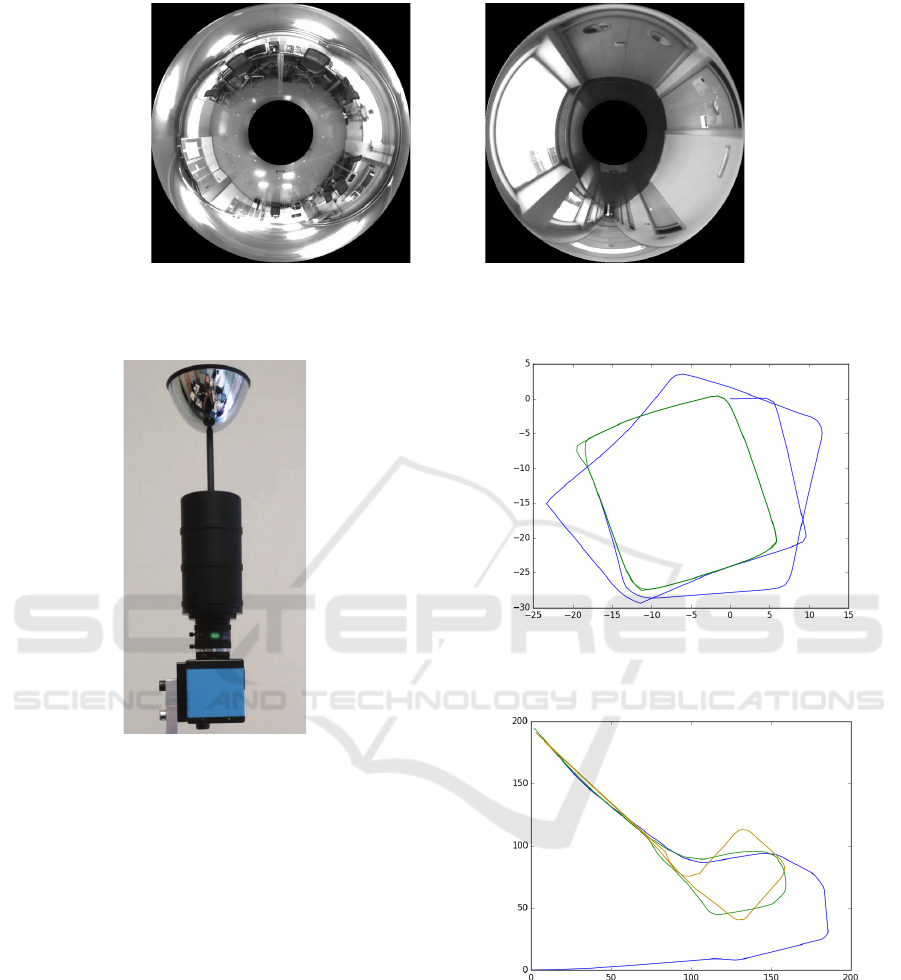
(a) (b)
Figure 4: (a) Sample omnidirectional image of the rectangular path. (b) Sample image of the second path.
Figure 5: Omnidirectional acquisition system.
optimization is made in each iteration but the map
without any optimization is shown to view the differ-
ence. As we can see, the green line is a square path.
Figure 7 shows the same results than in Figure 6
but using the second path. The blue line is the map
created without optimization, the green line is the
same map optimized and the yellow line is the ground
truth.
As for the computational time, the robot spends an
average of 0.65 seconds in each iteration of the SLAM
process. This time is increasing in each iteration be-
cause the map is formed by larger amount of nodes
and the loop closure detection needs to compare an
higher number of HOG descriptors.
5 CONCLUSIONS
In this paper we have presented a SLAM method to
estimate the position and orientation of a mobile robot
Figure 6: Map created using the first path. The blue line is
the map created without optimization and the green line is
the same map optimized.
Figure 7: Map created using the real path. The blue line is
the map created without optimization, the green line is the
same map optimized and the yellow line is the ground truth.
in an environment while the robot is creating the map.
We use two different global appearance descriptors to
carry out the SLAM process and the map is formed by
these two descriptors of each image. At last, the algo-
rithm has been tested with two sets of images captured
in two different indoor environments.
The results have demonstrated the accuracy of the
method. As for the values of the parameters, the max-
SLAM Algorithm by using Global Appearance of Omnidirectional Images
387

imum threshold of distance between HOG descriptors
is the main tuning parameter in this method.
The results presented in this paper show the effec-
tiveness of the global appearance descriptors of omni-
directional images to do SLAM thanks to the richness
of the information they contain. We are now work-
ing to improve this method and we are trying to esti-
mate more accurately the relative orientation between
nodes. Furthermore, we are implementing a cluster-
ing method to reduce the computational time to detect
loop closures when the number of nodes is increased.
ACKNOWLEDGEMENTS
This work has been supported by the Spanish
government through the project DPI2016-78361-R
(AEI/FEDER, UE) “Creaci
´
on de Mapas Mediante
M
´
etodos de Apariencia Visual para la Navegaci
´
on de
Robots’.”
REFERENCES
Bay, H., Tuytelaars, T., and Gool, L. (2006). Surf:
Speeded up robust features. Computer Vision at
ECCV, 3951:404–417.
Berenguer, Y., Pay
´
a, L., Ballesta, M., and Reinoso, O.
(2015). Position estimation and local mapping us-
ing omnidirectional images and global appearance de-
scriptors. Sensors, 15(10):26368.
Chang, C., Siagian, C., and Itti, L. (2010). Mobile
robot vision navigation and localization using gist and
saliency. In IROS 2010, International Conference on
Intelligent Robots and Systems, pages 4147–4154.
Dalal, N. and Triggs, B. (2005). Histograms of oriented gra-
dients for human detection. In 2005 IEEE Computer
Society Conference on Computer Vision and Pattern
Recognition (CVPR’05), volume 1, pages 886–893
vol. 1.
Fern
´
andez, L., Pay
´
a, L., Reinoso, O., Jim
´
enez, L., and
Ballesta, M. (2016). A study of visual descriptors for
outdoor navigation using google street view images.
Journal of Sensors, 2016.
Garcia-Fidalgo, E. and Ortiz, A. (2015). Vision-based topo-
logical mapping and localization methods: A survey.
Robotics and Autonomous Systems, 64:1 – 20.
Hasegawa, M. and Tabbone, S. (2011). A shape descrip-
tor combining logarithmic-scale histogram of radon
transform and phase-only correlation function. In
2011 International Conference on Document Analysis
and Recognition (ICDAR), pages 182–186.
Hoang, T. and Tabbone, S. (2010). A geometric invari-
ant shape descriptor based on the radon, fourier, and
mellin transforms. In 20th International Conference
on Pattern Recognition (ICPR), pages 2085–2088.
Kobayashi, K., Aoki, T., Ito, K., Nakajima, H., and Higuchi,
T. (2004). A fingerprint matching algorithm using
phase-only correlation. IEICE Transactions on Fun-
damentals of Electronics, Communications and Com-
puter Sciences, pages 682–691.
Kuglin, C. and Hines, D. (1975). The phase correlation
image alignment method. In In Proceedings of the
IEEE, International Conference on Cybernetics and
Society, pages 163–165.
K
¨
ummerle, R., Grisetti, G., Strasdat, H., Konolige, K.,
and Burgard, W. (2011). G2o: A general framework
for graph optimization. In 2011 IEEE International
Conference on Robotics and Automation, pages 3607–
3613.
Lowe, D. (1999). Object recognition from local scale-
invariant features. In ICCV 1999, International Con-
ference on Computer Vision, volume 2, pages 1150–
1157.
Munguia, R., Urzua, S., and Grau, A. (2016). Delayed
monocular slam approach applied to unmanned aerial
vehicles. PLOS ONE, 11(12):1–24.
Nagahara, H., Yoshida, K., and Yachida, M. (2007). An
omnidirectional vision sensor with single view and
constant resolution. In 2007 IEEE 11th International
Conference on Computer Vision, pages 1–8.
Pay
´
a, L., Amor
´
os, F., Fern
´
andez, L., and Reinoso, O.
(2014). Performance of global-appearance descrip-
tors in map building and localization using omnidi-
rectional vision. Sensors, 14(2):3033–3064.
Pay
´
a, L., Fern
´
andez, L., Gil, L., and Reinoso, O. (2010).
Map building and monte carlo localization using
global appearance of omnidirectional images. Sen-
sors, 10(12):11468–11497.
Radon, J. (1917). Uber die bestimmung von funktio-
nen durch ihre integralwerte langs gewisser mannig-
faltigkeiten. Berichte Sachsische Akademie der Wis-
senschaften, 69(1):262–277.
Valiente, D., Gil, A., Fern
´
andez, L., and Reinoso, O. (2014).
A comparison of ekf and sgd applied to a view-based
slam approach with omnidirectional images. Robotics
and Autonomous Systems, 62(2):108 – 119.
Whelan, T., Salas-Moreno, R. F., Glocker, B., Davi-
son, A. J., and Leutenegger, S. (2016). Elasticfu-
sion: Real-time dense slam and light source estima-
tion. The International Journal of Robotics Research,
35(14):1697–1716.
Wu, J., Zhang, H., and Guan, Y. (2014). An efficient visual
loop closure detection method in a map of 20 million
key locations. In 2014 IEEE International Conference
on Robotics and Automation (ICRA), pages 861–866.
Zhu, Q., Yeh, M.-C., Cheng, K.-T., and Avidan, S. (2006).
Fast human detection using a cascade of histograms
of oriented gradients. In 2006 IEEE Computer Society
Conference on Computer Vision and Pattern Recogni-
tion (CVPR’06), volume 2, pages 1491–1498.
ICINCO 2017 - 14th International Conference on Informatics in Control, Automation and Robotics
388
