
Fuzzy and 2-DOF Controllers for Processes with a Discontinuously
Variable Parameter
Alexandra-Iulia Szedlak-Stinean
1
, Radu-Emil Precup
1
and Emil M. Petriu
2
1
Department of Automation and Applied Informatics, Politehnica University of Timisoara,
Bd. V. Parvan 2, 300223, Timisoara, Romania
2
School of Electrical Engineering and Computer Science, University of Ottawa,
800 King Edward, K1N 6N5, Ottawa, ON, Canada
Keywords: Classical PID Controllers, Digital and Experimental Results, Flexible Drive Dynamics, Fuzzy Controllers,
Mechatronics Application, Two-Degree-of-Freedom PID Controllers, Variable Moment of Inertia.
Abstract: The application with a discontinuously variable parameter (moment of inertia) discussed in this paper is
represented by an experimental setup, namely the Model 220 Industrial Plant Emulator (M220IPE), which
allows the testing of several control solutions by performing real-time experiments. This paper suggests a
simple state feedback control structure with three position controllers developed with the aid of linearized
mathematical models and particular features of the process. The control structures contain conventional
controllers (PID) and also advanced control solutions (Takagi-Sugeno PD+I fuzzy and two-degree-of-
freedom PID controllers). The aim of these control structures is to achieve good robustness, good disturbance
control behaviours regarding the model uncertainties and also to improve set-point responses. The proposed
control structures are validated by digital and experimental results obtained for three specific values of the
moment of inertia.
1 INTRODUCTION
Over the past two decades, the development of
mechatronics systems has led to a novel stage of
engineering design. By constantly evolving, these
systems exhibit increasing performances ensuring, as
shown in (Isermann, 2005), applicative and functional
versatility, intelligence and flexibility. Since in
various fields very good performance specifications
are imposed, the design of the control systems is also
important. If several process operating conditions
(e.g., moment of inertia) are involved as variable
parameters, the imposed specifications become even
more restrictive. In this regard, the degree of
complexity of the control subsystem of a mechatronics
application differs from one application to another and
may include relatively simple and advanced control
structures as well.
The representative mechatronics system described
in this paper considers a nonlinear and complex
laboratory equipment with adjustable inertia (ECP,
2010). One of the purposes of this paper is to illustrate
how the use of laboratory equipment of medium
complexity and of different control structures can be
made accessible, easily understandable and
increasingly attractive.
In this paper design and implementation details are
given regarding a state feedback control structure
(SFCS) for M220IPE with flexible drive dynamics.
The use of an SFCS offers no guarantee for the zero
steady-state control error. Taking into account that the
transfer function (t.f.) related to the inner control loop
has two real poles and two complex conjugated poles,
including the integral term in the state feedback
control in terms of extending the state does not assure
the imposed performance requirements (reduced
settling times and phase margins of 60
º
). That is the
reason why the SFCS is inserted in a control loop that
contains three types of position controllers: (1) a PID
controller, (2) a Takagi-Sugeno PD+I fuzzy controller
(TS-PD+I-FC) and (3) a two-degree-of-freedom PID
controller (2-DOF PID).
This paper offers fivefold contributions: 1. the
mathematical modeling of M220IPE with flexible
drive dynamics and the interpretation of these models
as benchmark type MMs, 2. the design and
implementation of the SFCS, 3. the development and
verification through simulations and experiments of
Szedlak-Stinean, A-I., Precup, R-E. and Petriu, E.
Fuzzy and 2-DOF Controllers for Processes with a Discontinuously Variable Parameter.
DOI: 10.5220/0006468504310438
In Proceedings of the 14th International Conference on Informatics in Control, Automation and Robotics (ICINCO 2017) - Volume 2, pages 431-438
ISBN: Not Available
Copyright © 2017 by SCITEPRESS – Science and Technology Publications, Lda. All rights reserved
431

the proposed SFCS with PID controllers for nine
cases, 4. the digital simulation and experimental
testing of the SFCS with PID controllers, TS-PD+I-
FCs and 2-DOF PID controllers in three most
favorable case studies (i.e., the case studies I.a, II.b
and III.c) dedicated to the position control of
M220IPE with flexible drive dynamics, and 5.
comparative analyses to prove the validity of all
control solutions. They are relevant in the field as they
offer cost-effective control structures, characterized
by a simple structure, design and implementation.
The paper is divided into the following sections:
the dynamic equations described in the process MM in
case of flexible drive dynamics and the system
parameters values are given in Section 2. The
structural properties of the process and the design and
implementation of the SFCS are offered in Section 3.
Three positioning control structures developed for
M220IPE with flexible drive dynamics are presented
in Section 4. The digital simulation and experimental
results obtained are shown in Section 5. The
conclusions are highlighted in Section 6.
2 ELECTROMECHANICAL
PLANT – M220IPE
The controlled system is a mechatronics application
that is composed of three individual subsystems,
namely the electromechanical component, the real-
time controller unit and the dedicated executive
software. The main subsystem is the
electromechanical plant, which comprises a drive
motor that is coupled to a drive disk by means of a
timing belt, a disturbance motor that is coupled via a
4:1 gear ratio to a load disk and a speed reduction
assembly that connects the drive and load discs.
The moment of inertia of the two discs can be
adjusted by adding or removing specific weights
(ECP, 2010; Stinean et al., 2013a; Stinean et al.,
2013b). The electromechanical plant can emulate a
variety of dynamic configurations tested by
employing a nonlinear MM that closely describes the
actual behaviour of the system. The schematic
structure of the controlled process is illustrated in
Figure 1.
2.1 Mathematical Models
The MM of the electromechanical plant with flexible
drive dynamics can be determined using the relations
(1) - (3), where the terms are described in (ECP, 2010;
Stinean et al., 2013a; Stinean et al., 2013b; Stinean et
al., 2015; Acho et al., 2013).
The dynamic equations that describe the process
in case of flexible drive dynamics are:
.0)(
,)(
21
1
.
2122
.
1
1
12
..
2
2
1
1
2
.
2
1
12
.
1
2
121
..
1
*
=+−++−
=−+−++
−−
−−−−
θθθθθ
θθθθθ
kkgrccgrcJ
TkgrkgrgrcgrccJ
ld
Ddr
(1)
with J
dr
*
, J
dr
, J
p
, J
ld
, gr and gr
’
expressed as
.12/' ,/6
, ,
,
,)()(
___
____
__
22'*
dplpdp
ldwlddlddrwdrddr
backlashldpdrpp
ldpdrdr
ngrnngr
JJJJJJ
JJJJ
grJgrJJJ
==
+=+=
++=
++=
−−
(2)
The state-space MM (SS-MM) of M220IPE with
flexible dynamics with θ
1
as the process output is
.][ ,][
,][ ,] [
,
4...114...11
4...1,2211
==
=
==
==
=
+=
jjii
jiij
T
cb
a
y
CB
Ax
xC
TBxAx
θθθθ
(3)
with the matrix elements shown in (4)
.0 0, 0, ,1
,0 ,0 ,/1 ,0
,/)( ,/
,/,/
1, 0, 0,,0
,/ ,/
,/)( ,/
0, 0, 1, ,0
14131211
4131
*
2111
1224443
1
1242
1
41
34333231
*1
1224
*1
23
*2
12122
*2
21
14131211
====
====
+−=−=
==
====
==
+−=−=
====
−−
−−
−−
cccc
bbJbb
JccaJka
JgrcaJkgra
aaaa
JgrcaJkgra
JgrccaJkgra
aaaa
dr
ldld
ldld
drdr
drdr
(4)
The application of the Laplace transform to (1)
considering that the initial conditions are zero, leads
to the following t.f.:
.)/(
,)/()/(
)],/([
)(d ,
,)(
),(/])([)(/)(
2
211
2
21212121
2
*
2
2
121
122
*
3
*
4
1
2
2
3
3
4
4
122
2
1
grkckcd
grccccccgrkJ
kJdgrccJ
ccJJJd
sdsdsdsdsd
sdksccsJsTs
ld
drld
drlddr
ldD
+=
++++
+=++
++==
+++=
+++=
θ
(5)
ICINCO 2017 - 14th International Conference on Informatics in Control, Automation and Robotics
432
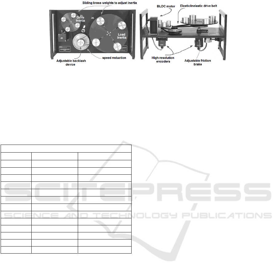
Figure 1: Electromechanical plant of M220IPE.
2.2 System Parameter Values
As given in the electromechanical plant manual
(ECP, 2010) the parameter values used for the design
of the SFCS are presented in Table 1.
Table 1: System parameter values.
Parameter values
Parameters Values Remarks
J
d_dr
0.00040 [kgm
2
]
J
d_ld
0.0065 [kgm
2
]
J
backlash
0.000031 [kgm
2
]
J
w_dr
0.0021 [kgm
2
]
4⋅0.2 kg at r
w_dr
=0.05 m
J
w_dr
0.00561 [kgm
2
]
4⋅0.5 kg at r
w_dr
=0.05 m
J
w_ld
0.00824 [kgm
2
]
4⋅0.2 kg at r
w_ld
=0.1 m
J
w_ld
0.0206 [kgm
2
]
4⋅0.5 kg at r
w_ld
=0.1 m
J
p_dr
or J
p_ld
0.000008 [kgm
2
] n
p_d
=24 or n
p_l
=24
J
p_dr
or J
p_ld
0.000039 [kgm
2
] n
p_d
=36 or n
p_l
=36
c
1
0.004 [Nm/rad/s]
c
2
0.05 [Nm/rad/s]
c
12
0.017 [Nm/rad/s]
k 8.45 [Nm/rad]
Because the laboratory application does not allow
a continuous moment of inertia variation, the proposed
control solutions that will be implemented on
M220IPE, analyzed and tested through digital
simulations and experiments will be developed for
three specific values of inertia of the load disk, J
ld
(Stinean et al., 2013a; Stinean et al., 2013b; Stinean
et al., 2015): the minimum value J
ld,min
=0.0065 kgm
2
(load disk with no weights on it), the average value
J
ld,avg
=0.01474 kgm
2
(four 0.2 kg weights positioned
at 0.1m from the load disk center) and the maximum
value J
ld,max
=0.0271 kgm
2
(four 0.5 kg weights
positioned at 0.1m from the load disk center).
There are totally nine possible combinations
between the process and controller parameters. The
t.f. in (5) and the matrix coefficients for the three
specific moment of inertia values are presented in
Table 2.
3 STATE FEEDBACK CONTROL
STRUCTURE
The use of the SFCS is based upon three main reasons:
1. the simultaneous control of all the essential process
variables (state variables) and the design of the
structure in relation to the evolution of these variables,
2. the stabilization of unstable processes, and 3. the
possibility to achieve the zero static control error by
extending the base structure.
The process structural properties are examined
considering the linearized SS-MMs and accounting
for the specific features of the nonlinearities. In this
regard, the controllability test of the linearized SS-
MMs (3) is conducted, using particularized parameter
values corresponding to defined operating points. The
state feedback controller contains a supplementary
amplifier with the k
AS
gain. Since the state feedback
gain matrix k
c
T
is of proportional type, the use of SFCS
does not prove to be effective regarding the zero
steady-state control error. The pole placement method
is applied to develop our SFCS, namely to actually
determine the parameter values of k
c
T
, using three sets
of poles for each value of the moment of inertia of the
load disk Using e
x
=w
x
-y
x
, y
x
=k
c
T
x and u=k
AS
e
x
, the SS-
MM of the SFCS is
,
AS
=
+=
xC
BxAx
x
y
wk
x
(6)
where A
x
=A-Bk
c
T
k
AS
is the system matrix of the inner
loop, and k
AS
=1. The expression of k
c
T
is
],[
4321 cccc
kkkk=
T
c
k
(7)
where T represents the transpose matrix and the gain
values are given in Table 3, columns 5, 6, 7 and 8.
The poles for the closed-loop system are also given in
Table 3 columns 1, 2, 3 and 4. The SS-MM of the inner
control loop leads to the t.f.
Fuzzy and 2-DOF Controllers for Processes with a Discontinuously Variable Parameter
433

,
)21)(1)(1(
)21(
)()(
22
21
22
1
sTsTsTsT
sTsTk
ssH
aaa
bbbSFCS
xSFCS
++++
++
=
=−=
−
ζ
ζ
BAIC
(8)
where T
1
, T
2
are the large time constants, T
a
is the
equivalent time constant, and ζ
a
is the damping
coefficient.
4 POSITIONING CONTROL
STRUCTURES FOR M220IPE
WITH FLEXIBLE DRIVE
DYNAMICS
This section presents the three proposed position
control structures developed to achieve the zero
steady-state control error specification, fulfilled by
the integral component of the controllers.
4.1 PID Controllers
The first state feedback control solution uses a
classical PID controller with the continuous-time t.f.
and tuning equations
,,),2/(1
,/)1)(1()(
22112
21
TTTTTkk
ssTsTksH
rrSFCSr
rrrr
===
++=
(9)
with k
r
– the controller gain, and T
r1
and T
r2
– the
controller time constants. After discretizing the
continuous-time PID controller using the backwards
difference method and setting the value of the
sampling period to h=0.004 s, the discretized t.f. is
,,,
),2(
,
),/()()(
102
1
2
0
1
10
2
2
1
10
1
hphpKq
KhKq
KhKhKq
zppzqzqqzH
d
dp
dip
r
−===
+−=
++=
+++=
−−−−
(10)
where K
p
=k
r
(T
r1
+T
r2
), K
i
=k
r
and K
d
=k
r
T
r1
T
r2
. The
PID controller parameter values for three significant
operating points obtained by Kessler’s Modulus
Optimum method (Åström and Hägglund, 1995) are
shown in Table 4, column 3.
4.2 Takagi-Sugeno PD+I Fuzzy
Controllers
Fuzzy controllers can be considered as easily
understandable initial controllers (Guerra et al., 2015;
Precup et al., 2015). This paper considers their design
and tuning such as to merge separately designed linear
controllers using the linearized process MM at several
operating points, justified as our controllers behave
like bumpless interpolators between linear controllers,
which is important due to the nonlinear input-output
map of fuzzy controllers and their adaptation to
process parameter changes.
The Takagi-Sugeno PD+I fuzzy block contains
the PD fuzzy controller in the parallel structure with
an integral (I) controller, i.e., the integral component
is implemented separately such that u
k
=u
PDk
+u
Ik
,
knowing that u
Ik
represents the output of this I
component. The PD quasi-continuous digital
controller and its parameters are derived from the PD
Table 2: State-space MM matrices and transfer functions expressions for M220IPE with flexible drive dynamics.
Moment of
inertia
Matrices A, B and C Process transfer function θ
1
(s)/T
D
(s)
J
ld,min
]0001[,
0
0
13850
0
,
307.10
1
13.10
0
1300
0
5036
0
654.0
0
068.12
1
325
0
1259
0
=
=
−−
−−
= CBA
)220782.267737.22(
)1300307.10(13850
23
2
+++
++
ssss
ss
J
ld,avg
]0001[,
0
0
13850
0
,
59.4
1
13.10
0
579
0
5036
0
3.0
0
068.12
1
145
0
1259
0
=
=
−−
−−
= CBA
)4.98277.189365.16(
)57959.4(13850
23
2
+++
++
ssss
ss
J
ld,max
]0001[,
0
0
13850
0
,
47.2
1
13.10
0
312
0
5036
0
157.0
0
068.12
1
9.77
0
1259
0
=
=
−−
−−
= CBA
)4.52904.159953.14(
)31247.2(13850
23
2
+++
++
ssss
ss
ICINCO 2017 - 14th International Conference on Informatics in Control, Automation and Robotics
434

Table 3: Numerical values of the selected poles and state feedback gain matrix.
Moment
of inertia
Flexible drive dynamics
Selected poles State feedback gain matrix
0
1 2 3 4 5 6 7 8
p
1
*
p
2
*
p
3
*
p
4
*
k
c1
k
c2
k
c3
k
c4
J
ld,min
-12.26 -48.49 -28.32+59.3317i -28.32-59.3317i 0.3234 0.0069 -0.7223 0.0247
J
ld,avg
-8.33 -26.32 -17.52+38.4817i -17.52-38.4817i 0.0749 0.0038 -0.1030 0.0124
J
ld,max
-4.95 -16.46 -17.38+31.3767i -17.38-31.3767i 0.0280 0.0030 -0.0155 0.0104
component by using
,//, ,/
),(
1221
121
dppd
kkkkPDk
KhKkkKkhKk
eekekeku
==α==
α+Δ=+Δ=
(11)
where Δe
k
=e
k
-e
k-1
represents the increment of the
control error, e
k
is the control error and u
PDk
represents the output of the PD fuzzy controller. The
developed TS-PD+I-FC substitutes the linear PD
component in the linear PID controller presented in
Sub-section 4.1. The fuzzification in TS-PD-FC is
realized using for each input, three input linguistic
terms LT
ek
and LT
∆ek
∈
{N, ZE, P} with trapezoidal
and triangular membership functions μ
e
, μ
Δe
. The
involved operators from the inference engine are
SUM and PROD and for defuzzification the weighted
average method is employed. In total for the complete
rule base, there are nine rules:
, then )N is and P is (If
, then )N is and E is (If
, then )N is and N is (If
, then ) ZEis and P is (If
, then ) ZEis and ZEis (If
, then ) ZEis and N is (If
, then )P is and
P is (If
, then )P is and ZEis (If
, then )P is and N is (If
b
PDkPDkkk
a
PDkPDkkk
c
PDkPDkkk
a
PDkPDkkk
c
PDkPDkkk
b
PDkPDkkk
c
PDkPDkkk
b
PDkPDkkk
a
PDkPDkkk
uuee
uueZe
uuee
uuee
uuee
uuee
uuee
uuee
uuee
=Δ
=Δ
=Δ
=Δ
=Δ
=Δ
=Δ
=Δ
=Δ
(12)
where
},,{ cba∈
χ
indicates the indices of the linear
PD controllers, namely a for C-J
ld,min
, b for C-J
ld,avg
,
and c for C-J
ld,max
:
./)]([ heeKu
kkdPDk
χ
χχ
α
+Δ=
(13)
The parameter B
∆e
is obtained by the modal
equivalence principle using the tuning equation
B
Δe
=min(α
χ
)B
e
, in which the B
e
parameter is specified
by the designer. The numerical values related to TS-
PD+I-FCs for three specific values of the load disk
moment of inertia are summarized in Table 4, column
4.
Figure 2: TS-PD-FC structure (a) and input membership
functions (b).
4.3 2-DOF PID Controllers
The advantages of using 2-DOF control solutions are
well known and concern reference tracking,
disturbance rejection and simultaneous good feedback
properties. Since multi-objective problems must be
solved to design control systems, a 2-DOF controller
has several advantages over a 1-DOF controller,
shown in (Leva and Bascetta, 2006). The 2-DOF
control structure illustrated in Figure 3 in a
formulation based on PID controllers is referred to as
2-DOF PID controller structure. Over the past two
decades many 2-DOF PID structures have been
developed (Leva and Bascetta, 2006; Alfaro et al.,
2009; Kevickzy and Banyasz, 2015), but in this paper
this structure was chosen for two main reasons: 1. the
simplicity of the structure, and 2. the ease of
transforming the PID controller into a 2-DOF
controller and vice versa. Using (Precup and Preitl,
2007; Precup et al., 2014), the main PID controller
component C
*
(s) and the additional block C
FB
(s),
highlighted in Figure 3, are described by the t.f.s
,
1
s
)(
])([k(s)
,)]()1(
1
)-[(1(s)C
CFB
*
f
d
i
C
sT
T
sD
sDC
sD
sT
k
+
=
+=
−++=
μτ
μτ
(14)
where k
C
, T
i
, T
d
, T
f
are the tuning parameters for the
2-DOF PID controller, k
C
(1-τ)=K
p
, T
i
=k
C
/K
i
and
T
d
(1-μ)=K
d
.
Fuzzy and 2-DOF Controllers for Processes with a Discontinuously Variable Parameter
435

Figure 3: 2-DOF PID structure.
The parameter values employed in the design of
this control solution are presented in Table 4, column
5.
5 DIGITAL AND
EXPERIMENTAL RESULTS
The SFCS described in Section 3 was developed and
tested on the M220IPE laboratory equipment in the
framework of three proposed position control
solutions. The parameter referred to as hardware gain
k
hw
=5.81 Nm/rad has been inserted in order to achieve
a higher controller internal numerical resolution. This
parameter also improves the encoder pulse period
measurement (ECP, 2010).
In order to avoid the oscillations produced by the
pair of complex conjugated poles and by the process
nonlinearities, four real poles were considered for the
proposed state feedback control solution. Because the
results are approximately similar with the ones
presented in this paper, this situation will not be
discussed any further, but the idea how the poles of the
inner loop can be modified may be the subject of future
research.
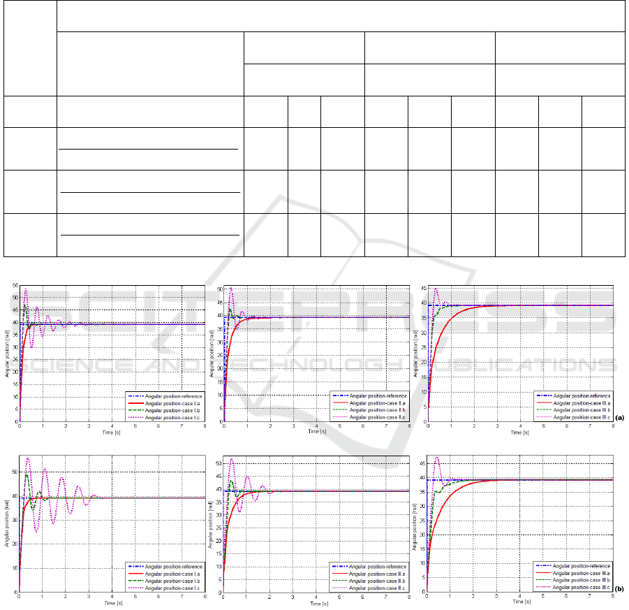
Analyzing the comparative simulation and
experimental results presented in Figure 4, the
following aspects can be concluded: in terms of the
best quality indices, both simulation and experimental
results show that the best performances have been
achieved in the cases I.a, II.b and III.c. The case I.a is
more effective – concerning the settling time value
(t
s
≈0.8661s) and also overshoot value (σ
1
≈0%) – than
the cases I.b and I.c; regarding the overshoot values,
the cases I.b and I.c exceed 22%; the case I.a offers
the highest performance in both digital and
experimental results and the worse result is obtained
by the case I.c; the case II.b exhibits the highest
performance regarding the settling time value
(t
s
≈1.1031) compared to the cases II.a (t
s
≈1.6604s)
and II.c (t
s
≈2.3932s); the overshoot value in this case
is around 8.65%; the case III.c has reached the highest
performance indices concerning the settling time
value (t
s
≈1.8006s) and first settling time value
(t
1
≈0.2836s) compared to the cases III.a (t
s
≈2.9723,
t
1
≈2.9521s) and III.b (t
s
≈2.0981s, t
1
≈2.0853); the case
III.a was the slowest one by exhibiting the largest
settling time value.
The three proposed position control solutions
described in Section 4 were tested and validated for the
electromechanical plant with flexible dynamics only in
the three most favourable cases – case I.a, case II.b and
case III.c – and the results are presented in Figure 5.
Taking this into account, by comparing the achieved
results, following conclusions can be drawn: (1) the
PID control solution was used for comparison and also
for the design of the other solutions; it was the least
favourable one achieving poor results in both settling
time and first settling time; (2) the 2-DOF PID control
solution is more effective – in all three cases
concerning the settling time and the first settling time
– in comparison with the PID control solution, but
worst in comparison to the TS-PD+I-FC control
solution; (3) all proposed solutions showed good
reference tracking behaviour and (4) the suggested
position controllers contribute in average to both
robustness and good dynamic performance regarding
at least one process parameter. Other effects will be
pointed out for other relevant applications including
those presented in (Filip, 2008; Mazdin et al., 2016).
6 CONCLUSIONS
This paper provided details regarding the development
of SFCSs aimed to control the position for a
mechatronics system built round the M220IPE
laboratory equipment. Since an SFCS doesn’t
guarantee the zero steady-state control error,
therefore it is included in a control loop that contains
three possible control structures with PID, TS-PD+I-
FC and 2-DOF PID controllers. Digital and
experimental results are given for three specific load
disk moment of inertia values.
The step responses in relation to the reference input
are used in the control structures comparison. The
comparison shows that the suggested solutions are
transparent and relatively easy to understand and to
employ, and the best reference tracking and control
system performance has been obtained in the cases
I.a, II.b and III.c. The controller C-J
ld,min
is suitable
for J
ld,min
and less suitable for J
ld,avg
and J
ld,max
. The
controller C-J
ld,avg
is suitable for J
ld,avg
and less
suitable for J
ld,min
and J
ld,max
. The controller C-J
ld,max
is
suitable for J
ld,max
and less suitable for J
ld,min
and J
ld,avg
.
The performance indices improvement for the
proposed control solutions using both model-based and
model-free tuning techniques will be the target of
future research. In addition, the pole placement will be
replaced with optimal parameter tuning.
ICINCO 2017 - 14th International Conference on Informatics in Control, Automation and Robotics
436
ACKNOWLEDGEMENTS
This work was supported by grants from the
Romanian Executive Agency for Higher Education,
Research, Development and Innovation Funding
(UEFISCDI), project number PN-II-RU-TE-2014-4-
0207, the Partnerships in priority areas – PN II
program of UEFISCDI, project numbers PN-II-PT-
PCCA-2013-4-0544 and PN-II-PT-PCCA-2013-4-
0070, and the NSERC of Canada.
Table 4: SFCS t.f.s. and numerical values of PID, TS-PD+I-FC and 2-DOF PID controllers.
Moment
of
inertia
Flexible drive dynamics
SFC structure t.f. H
SFCS
(s)
PID TS-PD+I-FC 2-DOF PID
3 4 5
1 2 K
p
K
i
K
d
k
1
k
2
α
k
C
T
i
T
d
J
ld,min
)000231.00131.01)(0815.01)(0206.01(
)00077.00079.01(9503.6
2
2
ssss
ss
++++
++
0.1123 1.1 0.0018 0.4617 0.1123 0.2433 0.1127 0.1024 0.0074
J
ld,avg
)000559.00196.01)(12.01)(0379.01(
)00172.00079.01(4588.20
2
2
ssss
ss
++++
++
0.1105 0.7 0.0032 0.7981 0.1105 0.1384 0.1108 0.1584 0.0142
J
ld,max
)000777.00270.01)(202.01)(0607.01(
)0032.00079.01(2229.41
2
2
ssss
ss
++++
++
0.0919 0.35 0.0043 1.0729 0.0919 0.0857 0.0925 0.2643 0.0287
Figure 4: Digital (a) and experimental (b) results concerning the behaviour of SFCs with PID controllers designed for
M220IPE with flexible drive dynamics: cases I.a-I.c, cases II.a-II.c and cases III.a-III.c.
Fuzzy and 2-DOF Controllers for Processes with a Discontinuously Variable Parameter
437
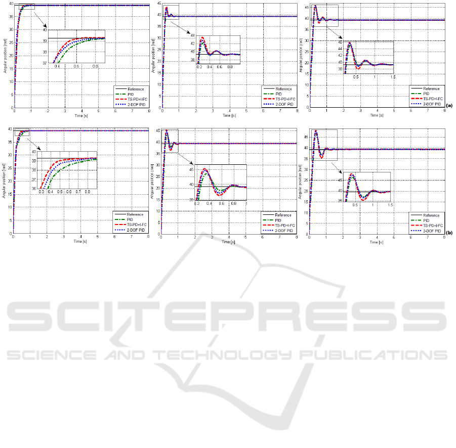
Figure 5: Digital (a) and experimental (b) results concerning the behaviour of SFCS with three proposed control solutions
developed for M220IPE with flexible drive dynamics: case I.a, case II.b and case III.c.
REFERENCES
Acho, L., Ikhouane, F., Pujo, G., 2013. Robust control
design for mechanisms with backlash. Journal of
Control Engineering and Technology. 3, 175–180.
Alfaro, V. M., Vilanova, R., Arrieta, O., 2009. Robust
tuning of Two-Degree-of-Freedom (2-DoF) PI/PID
based cascade control system. Journal of Process
Control. 19, 1658–1670.
Åström, K. J., Hägglund, T., 1995. PID Controllers Theory:
Design and Tuning. Research Triangle Park, NC:
Instrument Society of America.
ECP. 2010. Industrial Emulator/Servo Trainer Model 220
System, Testbed for Practical Control Training. Bell
Canyon, CA: Educational Control Products.
Filip, F. G., 2008. Decision support and control for large-
scale complex systems. Annual Reviews in Control. 32,
61–70, Apr. 2008.
Guerra, T. M., Sala, A., Tanaka, K., 2015. Fuzzy control
turns 50: 10 years later. Fuzzy Sets and Systems. 281,
168–182.
Kevickzy, L., Banyasz, C., 2015. Two-Degree-of-Freedom
Control Systems: The Youla Parameterization Approach.
Academic Press, Elsevier.
Leva, A., Bascetta, L., 2006. On the design of the feed-
forward compensator in two-degree-of-freedom
controllers. Mechatronics, 16, 533–546.
Isermann, R., 2005. Mechatronic Systems: Fundamentals.
Berlin, Heidelberg, New York: Springer-Verlag.
Mazdin, P., Arbanas, B., Haus, T., Bogdan, S., Petrovic, T.,
Miskovic, N., 2016. Trust consensus protocol for
heterogeneous underwater robotic systems. IFAC-
PapersOnLine, 49, 341–346.
Precup, R.-E., Angelov, P., Costa, B. S. J., Sayed-
Mouchaweh, M., 2015. An overview on fault diagnosis
and nature-inspired optimal control of industrial
process applications, Computers in Industry. 74, 75–94.
Precup, R.-E., David, R.-C., Petriu, E. M., Preitl, S., Radac,
M.-B., 2014. Novel adaptive charged system search
algorithm for optimal tuning of fuzzy controllers. Expert
Systems with Applications. 41, 1168–1175.
Precup, R.-E., Preitl, S., 2007. PI-fuzzy controllers for
integral plants to ensure robust stability. Information
Sciences. 177, 4410–4429.
Stinean, A.-I., Bojan-Dragos, C.-A., Precup, R.-E., Preitl,
S., Petriu, E. M., 2015. Takagi-Sugeno PD+I fuzzy
control of processes with variable moment of inertia.
In Proc. 2015 International Symposium on Innovations
in Intelligent Systems and Applications. Madrid,
Spain, 1-8.
Stinean, A.-I., Preitl, S., Precup, R.-E., Dragos, C.-A.,
Radac, M.-B., Petriu, E. M., 2013a. Modeling and
control of an electric drive system with continuously
variable reference, moment of inertia and load
disturbance. In Proc. 9
th
Asian Control Conference.
Istanbul, Turkey, 1–6.
Stinean, A.-I., Preitl, S., Precup, R.-E., Dragos, C.-A.,
Radac, M.-B., Petriu, E. M., 2013b. Low-cost neuro-
fuzzy control solution for servo systems with variable
parameters. In Proc. 2013 IEEE International
Conference on Computational Intelligence and Virtual
Environments for Measurement Systems and
Applications. Milano, Italy, 156–161.
ICINCO 2017 - 14th International Conference on Informatics in Control, Automation and Robotics
438
