
Using Geometry to Detect Grasping Points on 3D Unknown Point Cloud
Brayan S. Zapata-Impata, Carlos M. Mateo, Pablo Gil and Jorge Pomares
Physics, System Engineering and Signal Theory, University of Alicante, 03690 Alicante, Spain
Computer Science Research Institute, University of Alicante, Alicante, Spain
Keywords:
Grasping, 3D Point Clouds, Surface Detection, Handle Grasping, Unknown Object Manipulation.
Abstract:
In this paper, we focus on the task of computing a pair of points for grasping unknown objects, given a single
point cloud scene with a partial view of them. The main goal is to estimate the best pair of 3D-located points
so that a gripper can perform a stable grasp over the objects in the scene with no prior knowledge of their
shape. We propose a geometrical approach to find those contact points by placing them near a perpendicular
cutting plane to the object’s main axis and through its centroid. During the experimentation we have found
that this solution is fast enough and gives sufficiently stable grasps for being used on a real service robot.
1 INTRODUCTION
The task of grasping objects using robots such as grip-
pers have been widely studied in the state-of-art. Of-
ten, to accomplish autonomous robots and to specifi-
cally carry out the grasping task, the researchers use
information acquired from visual sensors (Gil et al.,
2016). In the past, the proposed approaches usually
recognised the object in the scene from one or more
views and later detected potential grasping points us-
ing a previously stored 3D model of that object. These
points can be also computed considering the grasping
problem as a classification task, where large datasets
are required for training and testing.
In this paper, we use a single point cloud with a
partial view of the objects present in the scene. More-
over, the objects are unknown, hence they have not
been previously recognised and we have not a 3D
model to compute candidate grasping points. Our
main goal is to estimate the best pair of 3D-located
points so that a gripper can perform a stable grasp
over the object with no prior knowledge.
Recently, several authors have developed learning
approaches to this problem by finding a gripper con-
figuration using a grasping rectangle. (Jiang et al.,
2011) introduced this idea representing a 2D oriented
rectangle in the image with two of the edges corre-
sponding to the gripper plates and the two other edges
representing its width. Originally, the authors used
RGBD images to find the optimal grasping rectangles
by using a ranking linear function, learnt using a su-
pervised machine learning algorithm.
Afterwards, this grasping rectangle has been
learnt using deep learning techniques in recent years.
Thereby, (Lenz et al., 2013) used RGBD images to
train a deep neural network that generated a set of
rectangles ranked by features obtained from the data
contained inside the bounds of the grasping rectangle.
In (Wang et al., 2016) the authors built a multimodal
Convolutional Neural Network (CNN) instead.
Some authors have tested the grasping rectangle
calculation using a different set of features apart from
the RGBD channels. For instance, (Trottier et al.,
2016) used RGBD images including more features
like grey maps and depth normals. In (Redmon and
Angelova, 2015), the authors’ proposal consisted not
on adding more channels to the images but on using
only the Red, Green and the Depth one.
Although learning approaches have proved to be
highly accurate, they require a significant amount of
data and time to fine tune the learning architectures
and the input features in order to be able to generalise.
Another frequently taken path to solve this prob-
lem consists on reconstructing a mesh from the seen
object to compute the grasping points on complete
CAD models or retrieve them from template grasps.
In (Varley et al., 2015), the authors proposed a system
that consisted on segmenting point clouds to find the
objects in the scene, then they reconstructed meshes
so the GraspIt! simulator (Miller and Allen, 2004)
could find the best grasp configuration.
In (Vahrenkamp et al., 2016), authors proposed a
database of grasps templates over segmented meshes.
During online grasping calculation, the robot would
154
Zapata-Impata, B., Mateo, C., Gil, P. and Pomares, J.
Using Geometry to Detect Grasping Points on 3D Unknown Point Cloud.
DOI: 10.5220/0006470701540161
In Proceedings of the 14th International Conference on Informatics in Control, Automation and Robotics (ICINCO 2017) - Volume 2, pages 154-161
ISBN: Not Available
Copyright © 2017 by SCITEPRESS – Science and Technology Publications, Lda. All rights reserved
decompose the object’s RGBD image in meshes of
primitive forms to match them against the templates.
Following this same idea, (Jain and Argall, 2016) pro-
posed an algorithm to match real objects against ge-
ometric shape primitives, with fixed grasping strate-
gies, using point clouds.
However, these solutions do not generalise well to
unseen objects since they are restricted to those forms
previously recorded and they need additional views in
order to reconstruct correctly the objects.
As for using point clouds and not only RGBD
images, (Richtsfeld and Vincze, 2008) proposed a
method for computing a pair of grasping points over
point clouds. Firstly, they searched for the top planar
surface of the object and then picked the closest point
in the rim to the object’s centre of mass. The sec-
ond grasping point was on the opposite rim. Similar
to this geometric approach, (ten Pas and Platt, 2015)
computed grasping candidates analytically locating
antipodal grasps. This work was later followed by an-
other approach where the authors localised hand-like
areas in the object’s cloud (ten Pas and Platt, 2016).
On this paper, we present a novel algorithm for
robotic grasping with grippers capable of detecting
grasping points on unknown objects using a single
point cloud view. This method automatically seg-
ments the point cloud to detect the objects present in
the scene. Then, for each of them, it calculates a set of
contacting points that fulfil certain geometric condi-
tions and ranks their feasibility to find the most stable
grasp given the view conditions.
The rest of the paper is ordered as follows: section
2 describes the robotic hand constraints and the ob-
jects geometry as well. Section 3 details the method
used for segmenting the input cloud, finding the can-
didate grasping points areas and ranking them for se-
lecting the best grasping pair of points. Section 4
shows the results obtained using a dataset of every-
day objects and section 5 presents our conclusions.
2 GEOMETRIC AND
KINEMATICS CONSTRAINTS
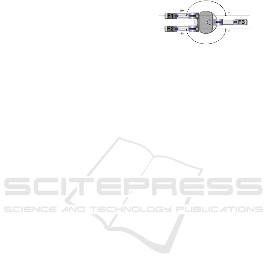
2.1 Hand Kinematic
For this work, we take into account only the physi-
cal limitations of a robotic hand for testing the con-
tact points generated. The hand used is the Barrett
hand, shown in figure 1. This hand is an under-
actuated grasper typically used in industrial scenarios
with three fingers, two of them that spread, counting
with 4 degrees of freedom.
Figure 1: Barrett robotic hand. Reproduced from
(Townsend, 2000).
In this work, we will use only two fingers, F1 and
F3, as a gripper. The maximum working aperture
gripper max amp of this hand is equal to 335mm and
their tip width gripper tip width is equal to 25mm.
These attributes will influence the contact points cal-
culation.
2.2 Object Geometry
We use for this work opaque, rigid objects which have
at least one dimension smaller than the maximum
working aperture of the robotic gripper. These objects
are restricted to be opaque due to the limitations of the
depth camera used with which RGBD images are ac-
quired using projected coded IR patterns. Transparent
objects or dark ones would not be detected properly
due to the wavelength of the emitted light that can be
reflected or refracted by some materials.
As for their stiffness, we are not dealing with
deformable bodies nor objects with holes passing
through them (all objects are compacts). This as-
sumption is required in order to avoid deformations
or noise that would affect the calculation.
3 GRASPING POINT SELECTION
In order to select the best grasping points for the grip-
per, we first need to segment the scene where the ob-
jects are presented. Then, a candidate area in the ob-
jects surface is found for each of the plates and com-
binations of points from these areas are ranked using
a custom function so the best configuration can guar-
antee the most stable grasp under the view conditions.
3.1 Scene Segmentation and Object
Detection
Given a recorded point cloud C, we first need to de-
tect objects in the scene. In order to do so, we be-
gin by filtering out points p ∈ C whose z-component
fulfil p
z
> 1m so we are left only with points closer
to the camera. Then, the ground plane Π
g
, where
objects are laying, is detected with RANSAC (Fis-
chler and Bolles, 1981). Once the points p ∈ Π
g
Using Geometry to Detect Grasping Points on 3D Unknown Point Cloud
155
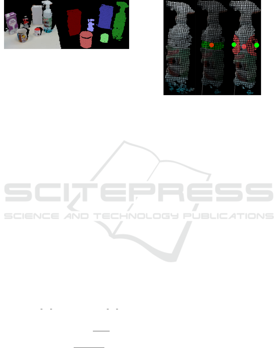
Figure 2: Scene segmentation. (left) original registered
point cloud, (right) detected objects after plane segmenta-
tion and clusters detection.
are extracted from C, an Euclidean Cluster Extraction
(Rusu, 2010)(Rusu and Cousins, 2011) is passed to
detect each of the objects point clouds C
k
. The results
of this process are displayed in figure 2.
3.2 Grasping Areas
Afterwards, an object to be grasped is selected. Its
point cloud C
k
is preprocessed to filter outliers from
its surface. Next, the centroid of C
k
is computed. In
addition, the main axis ~v of the cloud is obtained in
order to approximate the object’s largest axis. Hav-
ing done so, a cutting plane Π perpendicular to such
direction~v through the object’s centroid is calculated.
In the intersection of the plane Π and the cloud C
k
,
we subtract a set of points γ ⊂ C
k
that are within 1cm
to the plane Π, being this distance the best one found
empirically.
If the object’s axis~v is parallel to the ground plane
Π
g
, the points located in the two opposite areas along
the Z axis of the camera are the candidate grasping
points. Otherwise, the candidates are in the opposite
sides of the X axis from the camera viewpoint. The Y
axis is avoided since it includes the object’s points in
contact to the ground plane Π
g
.
In order to find these candidate grasping points,
the points p
min
∈ γ and p
max
∈ γ with the minimum
and maximum component value (X or Z depend-
ing on the case) are selected. This way, two can-
didate points clouds C
min
and C
max
are extracted us-
ing two spheres S
min
and S
max
centred in p
min
and
p
max
respectively. Their radius are initially equal to
r = 2 ∗ gripper tip width, being gripper tip width
the gripper’s plate width in millimetres. However, in
case the object’s width w
ob j
= L
2
norm(p
min
, p
max
) fits
the condition w
ob j
≤ 2 ∗ r, then r =
w
ob j
∗0.9
2
to adapt
the grasp area to the object’s size.
L
2
norm(p,q) =
s
n
∑
i=1
(p
i
− q
i
)
2
(1)
Based on this, the candidate point clouds C
min
and C
max
include those points belonging to the ob-
ject’s cloud C
k
which are within the volume of the
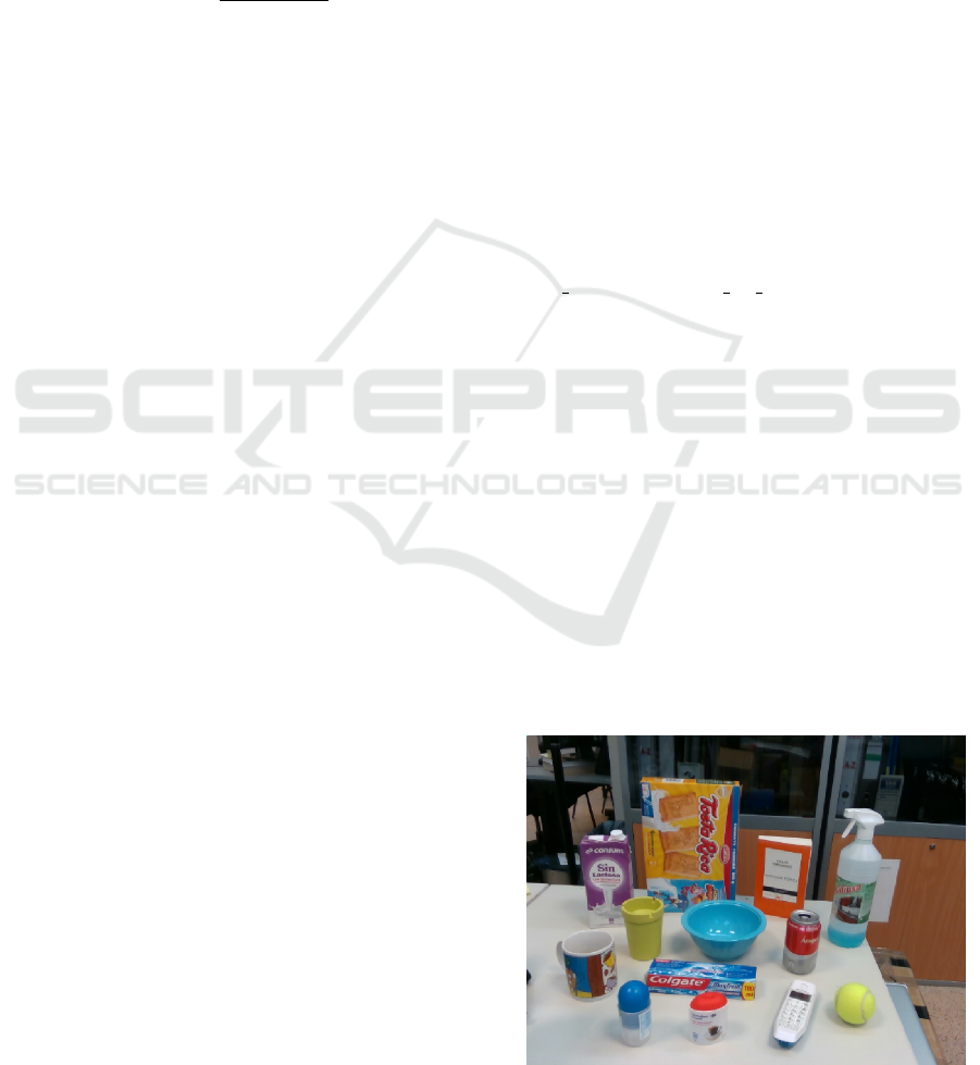
Figure 3: Grasping areas detection. (left) original object’s
point cloud C
k
, (middle) filtered cloud, centroid detected as
a red sphere, object’s axis~v as a white line and cutting plane
Π represented in green, (right) initial points p
min
and p
max
in green as well as candidate points clouds C
min
and C
max
coloured in red.
sphere S
min
and S
max
. That is, C
min
= S
min
∩C
k
and
C
max
= S
max
∩C
k
. In figure 3, we show the process of
detecting the grasping areas.
3.3 Grasping Points Ranking
As for ranking a grasp configuration Θ = {p
1
∈
C
min
, p
2
∈ C
max
}, we propose a function that evaluates
their stability depending on the following factors:
1. Distance to the Grasp Plane Π: this plane is cut-
ting the object through its centroid so the closer
the grasping points p
1
and p
2
are to the plane Π,
the closer they are to a reference to the object’s
centre of mass. This could be translated to an
equilibrated grasp. This distance is obtained as:
distance(Π, p) = abs(~n · p + o f f set) (2)
where ~n is the unitary normal vector of the plane
Π, p is one of the grasping points p
1
or p
2
and
o f f set is the distance of the plane Π to the origin.
2. Point’s Curvature: the curvature measures the
variations on the object’s surface. A grasp is likely
to be more stable if it is executed over a planar
area instead of highly curved points. In partic-
ular, the point’s curvature measures the variation
between this one and its neighbours on the same
surface. Both, the size (radius of sphere) and the
number of points (dense of sphere) influence the
estimation of the curvature values. To estimate
the curvature, we apply the method presented in
(Pauly et al., 2002). Thereby, we first compute the
covariance matrix of points within the sphere and
ICINCO 2017 - 14th International Conference on Informatics in Control, Automation and Robotics
156
obtain the eigenvalues and eigenvectors from Sin-
gular Value Decomposition (SVD). The covari-
ance matrix is previously obtained from a Princi-
ple Component Analysis (PCA). Later, the eigen-
values sum supplies surface variation information
between each point of the sphere and its centroid
and, the smallest eigenvalue gives us the variation
along the normal vector to the surface. Accord-
ingly, the curvature can be computed as:
λ
p
=
λ
0
λ
0
+ λ
1
+ λ
2
(3)
where λ
p
is the curvature on the point p, λ
i
is each
eigenvalue of the covariance matrix being i = 0
the smallest and i = 2 the biggest eigenvalue, re-
spectively.
3. Antipodal Configuration: in an antipodal grasp
the gripper is able to apply opposite and collinear
forces at two points. In this case, a pair of contact
points with friction is antipodal if they lay along a
line parallel to the direction of finger motion. To
guarantee this, the angle α between the ith-contact
point’s normal ~n
i
and the line ~w connecting p
1
and
p
2
should be close to zero.
4. Perpendicular Grasp: since the grasping areas
are spherical, there are chances for a candidate
grasp to not be parallel to the cutting plane Π. In
order to avoid trying to execute slippery grasps,
we penalise those configurations which are not
parallel to the cutting plane Π. That is, the line
~w which connects the grasping points p
1
and p
2
should have an angle β with the cutting plane’s
normal ~n close to 90 degrees.
Assuming these conditions, the following is the
proposed ranking function for a grasp Θ:
rank(p
1
, p
2
) =w1 ∗ r1(p
1
, p
2
) + w2 ∗ r2(p
1
, p
2
)
r1(p
1
, p
2
) =1.0 − dis(Π, p
1
)
2
+ 1.0 −dis(Π, p
2
)
2
+
1.0 − cos(β)
r2(p
1
, p
2
) =1.0 − λ
p
1
+ 1.0 −λ
p
2
+
cos(α
p
1
) ∗ cos(α
p
2
)
(4)
where dis(Π, p
i
) is the distance of the grasping
point p
i
to the grasp plane Π as measured in equation
(2), and λ
p
i
is the curvature of the grasping point p
i
as measured in equation (3), and α
p
i
is the angle be-
tween the ith-grasping point’s normal ~n
i
and the con-
necting line ~w, and β is the angle between the cutting
plane’s normal ~n and the connecting line ~w.
We split our function rank in two sub-functions
r1 and r2 because they evaluate distinct attributes of
the grasp configuration Θ. As for r1, it evaluates the
geometrical position of the grasping points over the
object’s surface. The curvature characteristics of their
area are evaluated by r2. These two natures are then
weighted using w1 and w2 to balance their influence
in the ranking function. In this work, w1 = w2 so both
factors have the same importance.
The values included in this ranking function are all
in the range [0,1] so ranking values vary in the range
[0,6], being 6 the score given to best grasp configura-
tions while unstable ones are closer to 0. In addition,
point cloud normal vectors and curvatures are calcu-
lated previously using a a radius r = 3cm.
Furthermore, these candidate areas C
min
and C
max
are voxelised so that the calculus can be made faster.
It is not necessary using every single candidate point
because if a point has for example a high curvature
value, its neighbours are likely to be under very simi-
lar conditions. Thus, voxels are used as a represen-
tation of a tiny surface inside the candidate grasp-
ing area. These voxels are computed using a radius
dependant of the gripper’s tip width in a factor of
voxel radius = gripper tip width ∗ 0.5.
4 EXPERIMENTS
For this experimentation, we have acquired point
clouds using a RealSense SR300 depth camera. The
dataset of objects is composed of the following house-
hold objects: milk brick, toothpaste box, cookies box,
spray bottle, bowl, mug, plastic glass, book, can,
tennis ball, deodorant roll-on, pillbox and telephone.
These objects and the scene view from the camera are
presented in 4. Objects lay in a range from 40cm to
100cm from the camera base.
Our algorithm was implemented in C++ using the
library PCL 1.7 and tested on an Intel i7-4770 @ 3.4
GHz x 8 cores with 8 GiB of system memory. For
Figure 4: Experimentation set comprised of 13 objects.
Using Geometry to Detect Grasping Points on 3D Unknown Point Cloud
157
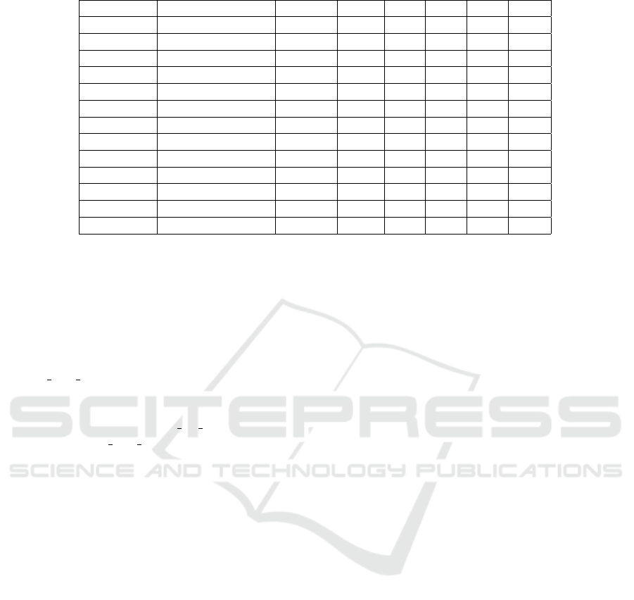
Table 1: Average grasp feasibility as a percentage and rank value for each object presented in isolation.
Object Dimensions (mm) # Views f
robot
f
env
r1 r2 rank
Toothpaste 46x190x38 6 1.00 1.00 2.38 1.04 3.42
Cookies 305x210x48 8 1.00 0.75 2.60 1.36 3.96
Milk 97x195x58 6 1.00 1.00 2.38 1.77 4.15
Book 123x202x25 6 1.00 0.83 2.72 1.33 4.05
Pillbox 58x77x37 6 1.00 1.00 2.51 1.11 3.62
Can 65x115x65 4 1.00 0.75 2.20 1.86 4.07
Roll-on 46x102x46 4 1.00 0.75 2.28 0.92 3.20
Spray 80x290x80 4 1.00 0.75 2.31 1.63 3.94
Mug 82x96x82 5 1.00 1.00 2.66 1.91 4.57
Glass 79x107x79 5 1.00 1.00 2.35 1.40 3.75
Bowl 172x78x172 4 1.00 0.75 2.76 2.08 4.84
Ball 63x63x63 2 1.00 1.00 2.80 1.57 4.38
Telephone 49x157x23 5 0.80 0.80 2.16 1.40 3.56
real time testing, it was implemented in ROS as a sub-
scriber node that read the camera data directly.
In the experiments, we will evaluate f
robot
as
the grasps feasibility constrained only to the hand
limitations by calculating the distance between the
grasping points. If it requires to open the gripper a
smaller width than its maximum operating amplitude
gripper max amp but they are not closer than a min-
imum distance, it is scored as a feasible grasp. Other-
wise, it is not physically possible to grasp it. For this
purpose, we have used gripper tip width as the min-
imum and gripper max amp as the maximum open-
ing width, being these the physical limitations of the
Barrett hand described in section 2.1.
Furthermore, the f
env
metric will evaluate the fea-
sibility of the grasp taking into account the environ-
mental constraints. For example, if a grasp requires
pushing the robotic hand under the object or both con-
tact points lay in the same surface the robot will col-
lide so it will be scored as infeasible.
4.1 Objects Presented in Isolation
For this experiment, the dataset objects were placed
alone on the table at a sufficient distance to be prop-
erly detected by the camera. In case of smaller ob-
jects like the pillbox or the ball this requires them to
be closer than bigger ones like the cookies box. Vari-
ous poses were taken and the proposed grasping algo-
rithm was run. In the table 1 we present the obtained
results.
Our dataset of objects is comprised of household
objects that can be categorised in some geometri-
cal types like boxes, cylinders and spheres. Box-
like objects were laid down in different positions so
each time the camera would acquired a new view of
it. Cylinders were laid down parallel to the Z axis,
as well as X axis and in diagonal to both of them.
Spheres are equally seen from every point of view so
they were moved along the Z axis to bring them closer
and further to the camera.
It can be observed that r1 usually contributes with
at least 2 out of 3 points to the ranking function. This
means that our ranking function is able to find good
contact points near the cutting plane that are paral-
lel to it. In our hypothesis, grasps parallel and close
to the cutting plane Π will be more stable since they
will be closer to the point cloud centroid, that can
be used as a representation of the object’s centre of
mass. Grasping closer to this point leads to more equi-
librated grasps if the object’s is proportionally dense
through its whole body, something that can be said for
most of the household objects a service robot would
manipulate.
Regarding r2, we have tested that box-like objects
tend to have lower scores on this function than cylin-
ders or spheres. In this function, we are ranking the
curvature of the contact point area and if they con-
figure an antipodal grasp as well. Planar objects will
have lower curvature values so it is logical to think
that these objects should have greater r2 values. How-
ever, due to only using one viewpoint of the object, it
is difficult to find more than two faces of boxes in the
same point cloud, making the configuration of an an-
tipodal grasps complicated. In order to configure one,
contact points should lay in two planes of the box with
normal vectors in the same direction but counter-wise.
Since this is not the case, our box grasps are penalized
by not configuring an antipodal grasp.
We have observed that the closer the objects are to
the camera, the more dense their point clouds are and
more information is available about its surface. That
results in higher ranked configurations due to having
more points to work with. That is, views that propor-
ICINCO 2017 - 14th International Conference on Informatics in Control, Automation and Robotics
158
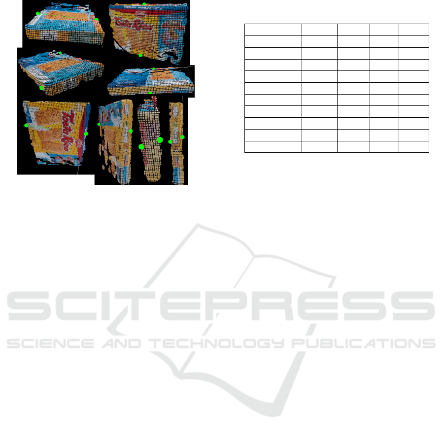
Figure 5: Samples of grasps calculated by the proposed al-
gorithm over the cookies box in different poses.
tion more information about the object’s shape facili-
tate finding better contact points.
Although the algorithm is designed to avoid rec-
ommending infeasible grasps like those that require
contacting the object through its lower surface, some-
times the recording conditions leads to grasps that
cannot be performed. As is shown in the table 1, f
robot
is usually equal to 100% meaning that every proposed
grasp is physically possible for our robotic hand.
However, during this experimentation, we found a
proposed grasp for the telephone that required posi-
tioning the grippers so close that they would collide.
This fact was due to displaying a lateral view of the
telephone that was very thin so any proposed grasp us-
ing such view required placing the grippers too close.
As for f
env
, it has been proved that sometimes, the
algorithm proposes grasps that are placed beneath the
objects, like the one displayed in the top right cor-
ner in figure 5. We have checked that this fact usu-
ally happens because the detected object’s main axis
is parallel to the table and there is enough noise to find
smaller Z values in lower parts than in the top of the
object so the initial point p
min
is placed wrong. This
is a case that our proposal treats incorrectly due to the
point cloud conditions.
4.2 Objects Presented in Clutter
In most of the real situations, the robot would face,
objects will not be isolated and they may be partially
occluded or surrounded by others. In these experi-
ments, we have distributed the dataset of all objects
on the work-table surface. In the table 2, we present
the results obtained by evaluating how many objects
were presented in real, how many were detected and
Table 2: Average objects presented in reality/detected, the
feasibility of their grasps and the rank for each object.
Scene # R/D f
robot
f
env
rank
Cylinders 6/5 1.00 0.60 3.55
Laying 7/7 1.00 0.71 3.97
Box-sphere 8/8 1.00 1.00 4.00
Cyl-sphere 8/7 0.85 0.85 4.16
Mix10-a 10/9 0.88 0.88 3.92
Mix10-b 10/10 1.00 0.90 4.01
Mix12-a 12/11 1.00 0.90 4.28
Mix12-b 12/12 1.00 0.91 3.73
Dataset-a 13/13 1.00 1.00 3.53
Dataset-b 13/14 1.00 0.78 3.68
how many had a feasible grasp calculated as well as
their mean rank.
We do not present these experiments in dense clut-
ter with objects contacting each other since that would
make the task of segmenting the objects using the
point cloud more difficult. Since we are not evaluat-
ing an object detection algorithm nor we are propos-
ing one, the objects presented in these experiments
are sufficiently separated to allow us test our contact
points calculation while still being in clutter.
Generally, all objects in the scene can be seen and
therefore detected. However, sometimes some objects
are missed since they are too occluded or small that do
not seem an object for the algorithm. Regarding the
objects detected, now that they are partially occluded
the rate f
env
decreases. Most of the erroneous pro-
posed grasps are due to being over objects in the back
so they are not properly seen or because the segment-
ing algorithm confuses two objects and mixes them in
the same object. These cases are displayed in the fig-
ure 6, where in the Mix12-a scene the toothpaste and
milk boxes are mixed in one single object. The same
happens in the Mix10-a scene with the mug and the
milk box.
Another issue for discussing is that when an object
is in front of another one, the object in the back can be
seen as two different point clouds. This fact is the case
of the milk box in the scene Dataset-b in the figure 6.
If those two boxes were separated objects, it could
be said that our algorithm is proposing two feasible
grasps. However, we know those grasps cannot be
executed. In a common clear-the-table task, we would
pick the toothpaste box and then recompute grasps for
the visible objects, solving this situation by doing so.
4.3 Real Time Testing
Apart from evaluating the contact points feasibility of
our proposed algorithm, we have tested its speed. For
this experiment, we have saved in rosbags 5 seconds
Using Geometry to Detect Grasping Points on 3D Unknown Point Cloud
159
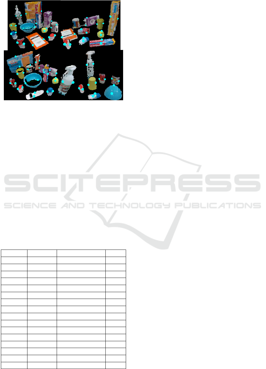
Figure 6: Samples of grasps proposed over clutter scenes.
Top: (left) Mix12-a, (right) Mix10-a. Bottom: (left)
Dataset-b, (right) Cyl-sphere.
of point clouds from our camera. Several objects con-
figuration were tested including the case of one single
object but with different sizes and a growing distri-
bution where the whole dataset of objects was intro-
duced one by one in each scene. Results are presented
in table 3.
As was expected, the average time needed to com-
pute the contact points for a single object depends on
its size. More specifically, it depends on the amount
of points processed. Bigger objects tend to have big-
ger point clouds so they are slower to process.
If just one single object is presented in the scene
the algorithm reaches a frames per second (FPS) rate
greater than 1. However, checking the dataset scenes
it can be observed that as we introduce more objects
Table 3: Average time calculating contact points for each
object in the scene and frames per second (FPS).
Scene # Objects Time/Object (ms) FPS
Cookies 1 530.00 1.30
Milk 1 45.61 11.45
Ball 1 26.94 17.13
Dataset 1 213.73 3.16
Dataset 2 126.04 2.84
Dataset 3 95.45 2.51
Dataset 4 80.08 2.10
Dataset 5 63.24 1.89
Dataset 6 84.00 1.19
Dataset 7 95.38 1.19
Dataset 8 96.24 1.10
Dataset 9 79.13 1.05
Dataset 10 84.03 0.92
Dataset 11 88.50 0.85
Dataset 12 78.60 0.81
Dataset 13 88.25 0.73
the proposed algorithm for detecting the objects and
then calculating their grasping points takes more time,
reducing the FPS rate. Nevertheless, the time required
to calculate a single pair of contact points is lowered
because we keep introducing more objects and then
bigger ones become occluded so their point clouds are
also reduced. This issue is also an effect of beginning
this test with greater objects at the back like the cook-
ies box of the spray and then keep introducing smaller
one in front of them so they can be easily detected.
Any single tested object took more than 1 second
to be detected and processed to give a grasp config-
uration. Therefore, it is fast enough to be used in a
real implementation as the grasping points calculation
system of a service robot.
5 CONCLUSIONS
In this paper, we propose a new algorithm for grasp-
ing novel objects with robotic grippers using 3D point
clouds and no prior knowledge. The main idea is to
geometrically find regions that fulfil a set of basic
conditions. These regions are found by calculating
the object’s main axis and its centroid. Then, a cut-
ting plane perpendicular to such axis and that holds
the object’s centroid is computed. This cutting plane
defines in the extremes of the object two candidate ar-
eas for placing the gripper plates. Configurations of
points combined from both areas are then ranked in
order to find the most stable and feasible grasp, tak-
ing into account their geometric positions in respect to
the cutting plane and their curvature characteristics.
Due to depending on the previous segmentation
of the scene and the calculation of the object’s main
axis, it is badly influenced by noise and poor point of
views of the objects to be grasped. Despite this fact,
it is still able to find always a pair of grasping points
in less than one second and stays as a useful basic
contact points calculation system.
In future work, we would like to extend it to make
full use of robotic hands with more than two fingers as
well as study a way to dynamically change the influ-
ence of r1 and r2 in the rank function by modifying
theirs weights w1 and w2. In addition, we want to test
this ranking function as a measure of the point of view
quality in terms of the best grasping points that can be
computed from it.
ACKNOWLEDGEMENTS
This work was funded by the Spanish Government
Ministry of Economy, Industry and Competitiveness
ICINCO 2017 - 14th International Conference on Informatics in Control, Automation and Robotics
160

through the project DPI2015-68087-R and the pre-
doctoral grant BES-2016-078290.
REFERENCES
Fischler, M. a. and Bolles, R. C. (1981). Random Sam-
ple Consensus: A Paradigm for Model Fitting with
Applicatlons to Image Analysis and Automated Car-
tography. Communications of the ACM, 24(6):381 –
395.
Gil, P., Mezouar, Y., Vincze, M., and Corrales, J. A. (2016).
Editorial: Robotic Perception of the Sight and Touch
to Interact with Environments. Journal of sensors,
2016(Article ID 1751205):1–2.
Jain, S. and Argall, B. (2016). Grasp detection for assistive
robotic manipulation. Proceedings - IEEE Interna-
tional Conference on Robotics and Automation, 2016-
June:2015–2021.
Jiang, Y., Moseson, S., and Saxena, A. (2011). Efficient
grasping from RGBD images: Learning using a new
rectangle representation. Proceedings - IEEE Interna-
tional Conference on Robotics and Automation, pages
3304–3311.
Lenz, I., Lee, H., and Saxena, A. (2013). Deep Learning for
Detecting Robotic Grasps. pages 1–4.
Miller, A. T. and Allen, P. K. (2004). GraspIt! IEEE
Robotics & Automation Magazine, 11(4):110–122.
Pauly, M., Gross, M., and Kobbelt, L. (2002). Efficient
simplification of point-sampled surfaces. 13th IEEE
Visualization conference., (Section 4):163–170.
Redmon, J. and Angelova, A. (2015). Real-time grasp de-
tection using convolutional neural networks. 2015
IEEE International Conference on Robotics and Au-
tomation (ICRA), pages 1316–1322.
Richtsfeld, M. and Vincze, M. (2008). Grasping of Un-
known Objects from a Table Top. Workshop on Vision
in Action: Efficient strategies for cognitive agents in
complex environments.
Rusu, R. B. (2010). Semantic 3D Object Maps for Everyday
Manipulation in Human Living Environments. KI -
Kunstliche Intelligenz, 24:345–348.
Rusu, R. B. and Cousins, S. (2011). 3D is here: Point Cloud
Library (PCL). Proceedings - IEEE International
Conference on Robotics and Automation, (April).
ten Pas, A. and Platt, R. (2015). Using Geometry to De-
tect Grasps Poses in 3D Point Clouds. Int’l Symp. on
Robotics Research.
ten Pas, A. and Platt, R. (2016). Localizing handle-like
grasp affordances in 3D point clouds. Springer Tracts
in Advanced Robotics, 109:623–638.
Townsend, W. (2000). The BarrettHand grasper-
programmably flexible part handling and assem-
bly. The International Journal of Industrial Robot,
27(3):181–188.
Trottier, L., Gigu
`
ere, P., and Chaib-draa, B. (2016). Dic-
tionary Learning for Robotic Grasp Recognition and
Detection. arXiv preprint, pages 1–19.
Vahrenkamp, N., Westkamp, L., Yamanobe, N., Aksoy,
E. E., and Asfour, T. (2016). Part-based Grasp Plan-
ning for Familiar Objects. 2016 IEEE-RAS Interna-
tional Conference on Humanoid Robots (Humanoids
2016).
Varley, J., Weisz, J., Weiss, J., and Allen, P. (2015). Gener-
ating multi-fingered robotic grasps via deep learning.
IEEE International Conference on Intelligent Robots
and Systems, 2015-Decem:4415–4420.
Wang, Z., Li, Z., Wang, B., and Liu, H. (2016). Robot
grasp detection using multimodal deep convolutional
neural networks. Advances in Mechanical Engineer-
ing, 8(9):1–12.
Using Geometry to Detect Grasping Points on 3D Unknown Point Cloud
161
