
Research on the Mission Critical Parameters Identification by using
Kinematic Boundaries
Jingyu Wang, Usman Fareed, Ke Zhang and Pei Wang
School of Astronautics, Northwestern Polytechnical University, Xi’an, China
National Key Laboratory of Aerospace Flight Dynamics, Northwestern Polytechnical University, Xi’an, China
Keywords:
Evaluation, Criteria, Kinematic, Simulations, Coarse, Fine, Frequency Distribution.
Abstract:
Finalization of missile system requirement specifications in design phase is critical in order to achieve user’s
expectations and to avoid unexpected outcomes. This is guaranteed through well defined performance eval-
uation criteria. A methodology is devised to finalize and evaluate missile sub-systems characteristics with
emphasis on its ability to meet mission specific goals. Missile system evaluation is achieved through comput-
ing kinematic boundaries against highly agile targets. Kinematic boundaries includes minimum and maximum
launch points. These launch points are the sequel of 3-DoF missile and target engagement simulations. In or-
der to reduce computation time, coarse and fine search has also been introduced. Mission critical sub-systems
are identified through relative frequency analysis. Once requirements are finalized, technical challenges asso-
ciated with respective sub-systems are eliminated by suggesting efficient missile launch strategies.
1 INTRODUCTION
Finalization of system requirement specification plays
a vital role in terms of acceptable outcomes for the
end user. Considerable amount of time and resources
were often allocated in the preliminary design phases
to avoid unexpected outcomes. The ample time dis-
pense in the initial requirement finalization will not
only expedite the development processes but also
saves substantial amount of resources. In the recent
years manytools and techniques havebeen introduced
that ease in the analysis of proposed requirements.
These tools not only reduce designers load but also
mitigate the chances of human errors in safety critical
applications. In complex aerospace programs, weak-
nesses and demerits associated with finalized system
requirements may results due to insufficient resources
or technical difficulties. Such imperfections can be
annihilated by incorporatingbetter deployment strate-
gies.
The task of finalizing initial requirements starts with
the development of prototypes. Prototypes are the ab-
stract representation of the actual system. In case of
complex and expensive systems prototypes are gen-
erally the computer based software modules. These
modules includes the mathematical representations of
vital sub-system characteristics. To get a quantita-
tive assessment of overall system, the need to de-
velop abstract level mathematical programscan not be
neglected (Moore, 2015). For the proof-of-concept,
the verification of system through prototypes with re-
markable cost-benefit ratio has been achievedthrough
automated tool like Model Analyzer/Checker (Stor-
rle, 2015). As illustrated in our study, the utilization
of abstract modules can play a vital role when evalu-
ated in an actual dynamic environment.
Many complex simulations have been developed to
evaluate system effectiveness in actual combat sce-
nario. Such simulations are it self a big pro-
grams like TISES which provides system evalua-
tions for THAAD, US anti-ballistic missile system
(Dawn Horn, 1997). These complex simulations re-
quire detailed level of system modeling. In order to
meet the needs of iterative design process, top level
exemplar comprising salient features are more effi-
cient in terms of time and cost.
Modern missile systems comprehend numerous sub-
systems that should be able to perform in an inte-
grated environment. Thus the lofty or rigid attributes
of one part will directly affect the performanceof over
all system. Like the aerodynamic of the missile is
linked with the airframe structures, bulky structures
have more strength but are less aerodynamically effi-
cient. Similarly optimum functionality of guidance
and control is associated with the stable output of
seeker and actuator systems. So studies and simula-
644
Wang, J., Fareed, U., Zhang, K. and Wang, P.
Research on the Mission Critical Parameters Identification by using Kinematic Boundaries.
DOI: 10.5220/0006470906440651
In Proceedings of the 14th International Conference on Informatics in Control, Automation and Robotics (ICINCO 2017) - Volume 1, pages 644-651
ISBN: 978-989-758-263-9
Copyright © 2017 by SCITEPRESS – Science and Technology Publications, Lda. All rights reserved
tions that ensure the balanced outcomes of each entity
without compromising on the performance of overall
system is pertinent in the realm of systems engineer-
ing (Kilian James C, 2016). In the preliminary design
stage, simple interactive models are enough to see the
influence of one element on the overall performance,
but in the validation period the detailed hardware in
loop simulations are often used to get the expected
outcomes (Chang Xiaofei, 2012). However, our pro-
posed scheme shall unmask the fact that even with
these abstract models, one can get acceptable results
when operational environment is also a part of our
simulations.
Performance of the missile system is often compro-
mised due to inadequate resources. To over come this
challenge different tactics and weapon deployment
strategies have been in use. To maximize engagement
envelop (James M. Davies and Oxtoby., 2011) used
probabilistic method to predict target location upon
detection. (Vergez, 1998) proposed the implementa-
tion of extended Kalman filter (EKF) to estimate the
target position from limited target acceleration data
provided by onboard passive seekers. However such
methodologies are difficult to meet the available time
budget in short range missile concepts. In case of
short range air-to-air combat, pilots also prefer their
experiences instead of relying on onboard guidance
optimization algorithms. Thus, our proposed evalua-
tion algorithm intend to educate the training pilots to
get maximum probability of kill by adopting those at-
tack angle where efficiency of respective sub-system
is maximum.
This paper recommends the usage of abstract level of
air-to-air missile prototypesto evaluatesystem perfor-
mance in early design phase. These evaluation stud-
ies are more efficient when incorporated with opera-
tional scenarios. The novelty associated with our re-
search is to demonstrate the utility of missile kine-
matic model in predicting mission critical parame-
ters. Also highlighted the application of proposed al-
gorithm in exploiting trade-offs between other com-
plex sub-systems. Technical challenges can be over
come through adopting tactical deployment strategies
which are also helpful to develop training simulators
for the pilots.
2 MATHEMATICAL MODEL OF
MISSILE AND TARGET
The three degree of freedom mathematical models
have been used to develop missile and target engage-
ment simulation. In this section these models shall be
discussed in detail.
2.1 Missile and Target Model
A 3-DoF point mass simulation is used for the mis-
sile and target simulations. Two frame of references
shall be used in this paper. One is north, east and
down (NED) inertial frame of reference and other is
the standard body frame, for reference see Fig. (1).
Equation of motion governing the dynamics of mis-
sile under the influence of thrust, drag and gravity in
inertial frame of reference are shown below;
˙
V
m
˙
Ψ
m
˙
γ
m
˙
X
i
m
˙
Y
i
m
˙
Z
i
m
=
T
m
−D
m
m
m
− gsin(γ
m
)
a
y
m
V
m
cos(γ
m
)
a
z
m
−gcos(γ
m
)
V
m
V
m
cos(γ
m
)cos(Ψ
m
)
V
m
cos(γ
m
)sin(Ψ
m
)
V
m
sin(γ
m
)
(1)
Figure 1: Inertial and body frame of reference.
Lift and drag coefficients in the form of look-up
table, are the function of mach number and angle of
attack. Thrust and mass are the function of time.
Other parameter and variable used in this simulation
are mentioned in the Tab. (1). Actual values of these
parameters are omitted here because of regulatory re-
strictions.
Table 1: Missile parameters and variables.
Parameter Description
S
ref
Surface Area(m
2
)
d Diameter(m)
m
m
Mass(Kg)
γ
m
Flight Path Angle(rad)
Ψ
m
Azimuth Angle(rad)
D
m
Drag(N)
X
i
m
,Y
i
m
,Z
i
m
Inertial Positions(m)
a
y
m
,a
z
m
Measured Accelerations(m/sec
2
)
T
m
Thrust(N)
V
m
Velocity(m/sec)
Missile guidance commands are generated form
conventional PN guidance law using Eq. (2), in which
the missile velocity vector rotate in a rate proportional
Research on the Mission Critical Parameters Identification by using Kinematic Boundaries
645

to the rotation rate of line of sight, and in the same
direction.
A
c
= N
˙
λV
c
(2)
Here A
c
is the commanded acceleration form PN law,
N is the navigationalconstant,
˙
λ andV
c
are the relative
to the target line of sight rate and velocity vector in
body frame of reference. Target is assumed to retain
its velocity magnitude once the missile is launched
from the aircraft. Target maneuvers in inertial frame
are implemented by using Eq. (3).
˙
V
t
= ng[ ˆv
t
× ˆn] (3)
Here n is the desired acceleration load factor, g is the
gravitational acceleration. ˆv
t
is the target’s velocity
unit vector and ˆn is the normal to plane unit vector,
on which target maneuver is required. For example if
target is required to perform a positive east side ma-
neuver in NE frame, then normal to plane unit vector
in NED inertial frame of reference is [0,0,−1].
3 PROBLEM STATEMENT WITH
FORMULATIONS
3.1 Problem Statement
Mission critical sub-system identification is the prima
for complex aerospace programs. (Kascha Christian,
2015) proposed moving average method for model
identification and performance evaluation through
Monte Carlo simulation. In case of missiles, re-
quired dynamic performance against the agile targets
make it difficult to finalize the sub-system specifi-
cation through probabilistic models (Yi Ping, 2014).
Hence research to identify and finalize key perfor-
mance indicators in operational scenario is studied
here. The lack of knowledge sharing between users
and program designers also limit the utility of prod-
uct to its full extent. Machine learning is suggested in
(Roehm Tobias, 2013) to identify mismatch between
user and developer. In this paper we devised knowl-
edge based deployment strategies of missiles to over-
come sub-system identification and limitations.
3.2 Proposed Formulations
The mathematical approach presented here is to first
implement missile kinematic model against the agile
target. Then missile sub-systems behaviour were an-
alyzed with varying parameters. Mission specific tar-
get models with relative frequency distribution were
studied to finalize critical sub-system characteristics.
Finally, remedial tactics in terms of initial launch con-
ditions shall be helpful in eliminating sub-systems re-
quirement limitations.
3.2.1 Kinematic Boundaries Computation
Kinematic boundaries consists of missile maximum
and minimum launch ranges. These boundaries are
the result of multiple simulations between missile and
target with monotonically varying initial conditions
using coarse and fine search techniques. The initial
geometry between missile and target is assumed to be
unchanged at the time of launch so monotonic search
is sufficient to provide required results 3.2.4. This
algorithm is used as a basic tool to access the kine-
matic capability of the missile to hit the target, with
pre-defined sub-system characteristics. The detail de-
scription to computed kinematic ranges is described
below;
3.2.2 Compute Maximum Range(Rmax)
Rmax is computed first using coarse search method
followed by fine search method. In coarse search,
first fly-out starts from the farthest possible launch
point w.r.t the target at specific aspect angle. The as-
pect angle is the angle between the body longitudinal
axis of the target and the LOS vector (Ronghui Zhan,
2012). This point indicates maximum detection range
of short range missile’s Eq. (4). If missile hits the tar-
gets, fine search method will further tune the results.
Upon miss, first fly-out comes closer to the target un-
til hit. Target is assumed to perform evasive maneuver
once missile is launched.
R
max0
= max(R
detect
(θ)) (4)
Where R
max0
is the starting point of first fly-out for
Rmax, R
detect
is the maximum detection range of mis-
sile seeker and θ is the target aspect angle. Binary
search is used to compute the fine search between
lower bound (LB) and upper bound (UB) provided by
coarse search. In case of Rmax computation, lower
bound is the last hit and upper bound in the last miss.
The purpose of binary search is to reduce the coarse
step error to fine step. The ratio of coarse to fine step
is 20:1, which is good enough to reduce the compu-
tation time. Pseudocode to compute binary search is
written below;
3.2.3 Compute Minimum Range (Rmin)
Rmin is computed first using coarse search method
followed by fine search method. In coarse search, first
fly-out starts from the nearest possible launch point
w.r.t the target at specific aspect angle see Eq. (5).
ICINCO 2017 - 14th International Conference on Informatics in Control, Automation and Robotics
646
Algorithm 1: Binary Search for Rmax Computa-
tion.
Data: Lower and upper values of coarse Rmax.
ranges
Result: Fine Range for Rmax.
while difference of upper lower bound greater
than fine step do
Update missile and target geometry based
on middle point;
if miss then
upper bound = middle point;
middle point = upper
bound-(difference)/2;
go back to read middle value;
else
lower bound = middle point;
middle point = lower
bound+(difference)/2;
go back to read middle value;
end
end
Upon miss, first fly-out goes farther from the target
until hit. Target is assumed to perform evasive ma-
neuver once missile is launched.
R
min0
= V
m
0
t
max
0
+
1
2
A
l
t
max
0
2
(5)
V
m
0
is the missile initial launch velocity, t
max
0
is the
time associated with launch button delay plus safe
and arming sub-system activation delay. A
l
is the ini-
tial longitudinal acceleration jerk from the launcher
necessary for the safe release of the missile. Binary
search is used to compute the fine search between
lower bound (LB) and upper bound (UB) provided
by coarse search. In case of Rmin computation, lower
bound is the last miss and upper bound is the last hit.
The purpose of binary search is to reduce the coarse
step error to fine step. The ratio of coarse to fine step
is in case of Rmin is also 20:1, to reduce the com-
putation time. Pseudocode to compute Rmin binary
search is mentioned below;
3.2.4 Sub-systems Dependence Formulations
Seeker system, structural characteristics and termi-
nal energy are the key characteristics to be evaluated.
Tab. (2) shows the maximum or minimum acceptable
criteria for each sub-system qualification. The en-
gagement simulation must stop upon expiry of any
criteria listed below. New search point for Rmax and
Rmin shall be adjusted to get the actual performance
of the missile against the desired targets.
In dog fight scenarios, target aircraft perform eva-
sive maneuvers or use after burner to out run the in-
Algorithm 2: Binary Search for Rmin Computa-
tion.
Data: Lower and upper values of coarse Rmin.
ranges
Result: Fine Range for Rmin.
while difference of upper lower bound greater
than fine step do
Update missile and target geometry based
on middle point;
if miss then
lower bound = middle point;
middle point = lower
bound+(difference)/2;
go back to read middle value;
else
upper bound = middle point;
middle point = upper
bound-(difference)/2;
go back to read middle value;
end
end
Table 2: Sub-systems evaluation criteria.
Sub-System Terminal Value Description
Seeker LA
max
Max. Look Angle
Seeker TR
max
Max. Track Rate
Control Power G
max
Max. Load
Propulsion −VC
max
Min. Closure Rate
coming missile. Thus the minimum energy required
by the missile should be evaluated after rocket motor
burns out.
Feasible terminal values mentioned in Tab. (2) largely
depends upon the available resources and users ex-
pectation. To get these estimates simulated analysis
is proposed here. Utility of such analysis is to inves-
tigate the trade-offs that might exist between various
section of the missile. Tab. (3) depicts the possible
sub-systems design ranges that can be examined and
formalized through kinematic simulation. The refer-
ence system details are also mentioned to compare
the differences resulted form one specific sub-system
variation.
Table 3: Sub-system design ranges.
Sub-System Range Ref. Value
Look Angle [30 to 50] 40(deg)
Track Rate [22 to 35] 30(deg/sec)
Closure Rates [-400 to -600] -500(m/sec)
Load or Control Power [15 to 20] 15
Diameter [5 to 7] 5(in)
Thrust [T
m
*1 to T
m
*1.3] T
m
(t)(N)
Mass [m
m
*1 to m
m
*1.3] m
m
(t)(Kg)
Research on the Mission Critical Parameters Identification by using Kinematic Boundaries
647
3.2.5 Mission Critical Parameter Identification
There is no generic formula to device requirement fi-
nalization. The ratified outcomes of a system highly
depends on an organizational resources, mission ob-
jectives and user satisfactions. Relative frequencies
of each sub-system in case of miss is devised to
identify critical sub-systems (Lin Chin-Yew, 2016)
and (Michael, 2015). Requirement finalization is
achieved by forcing relative frequency of each sub-
system at some moderate value without compromis-
ing on the missile performance. Kinematic envelop of
missile is enhanced once the mission critical relative
frequencies were reduced. Relative frequency of each
section when missile miss the target is computed us-
ing Eq. (6). This formulation can also help to allocate
major resource to those sub-systems that are mission
imperative.
f
s
=
m
s
∑
θ
m
s
(6)
f
s
is the relative frequency of each sub-system in case
of miss, m
θ
is the number of frequency of miss caused
by this sub-system at particular aspect θ divided by
the total number of missile miss at all aspect angles θ
(0
◦
to 360
◦
) influenced by this sub-system.
3.2.6 Remedial Tactics
Shortcomings associated with our finalized require-
ments can be eliminated through incorporating effi-
cient launch tactics. Frequency distribution in terms
of comparative histograms are computed. These his-
tograms show the number of miss caused by each sub-
system at specific aspect angle θ. Such distributions
can educate the pilots to avoid those aspect angles
where frequency distribution of particular sub-system
is maximum. Simulated results that can be helpful to
understand proposedremedial strategies are discussed
in section 4.
4 SIMULATION RESULTS
3-DoF simulated missile and target simulations shall
be used to compute missile kinematic ranges. These
ranges shall be the function of iterative fly-outs be-
tween missile and target engagements. RK4 numer-
ical integration is used to update missile and target
states (Z. Kalogiratou, 2010). Sub-system parametric
identification and finalization are carried against the
reference missile mentioned in Tab. (3) using initial
conditions tabulated Tab. (4). Following assumptions
are made to compute kinematic boundaries;
East(feet)
0 200 400 600 800 1000 1200 1400 1600 1800
North (feet)
-2000
-1500
-1000
-500
0
500
1000
1500
2000
3
2
1
Rmin-Flyouts
3
2
1
Msl
Tgt
Figure 2: Rmin fly-outs against 5g’s target turn.
East(feet)
× 10
4
0 0.5 1 1.5 2 2.5 3 3.5 4
North (feet)
× 10
4
-4
-3.5
-3
-2.5
-2
-1.5
-1
-0.5
0
0.5
1
2
3
4
5
6
Rmax-Flyouts
5
6
4
3
2
1
Msl
Tgt
Figure 3: Rmax fly-outs against 3g’s target turn.
1. Missile seeker always looked-on to the target.
2. Missile initial velocity vector aligned with the line
of sight vector.
3. Target aircrafts starts evasive maneuvering once
missile is fired from the aircraft.
4. Target evasive load factor to compute Rmax and
Rmin is 3g’s and 5g’s respectively.
Table 4: Initial conditions for parametric studies.
Msl. Vel Tgt. Vel Msl. Alt Tgt. Alt
200m/sec 200m/sec 10,000ft 10,000 ft
Rmin and Rmax fly-outs at specific aspect angle
are shown in Fig. (2) and Fig. (3) respectively. These
fly-outs are iteratively updated at every miss till hit is
achievedas mentioned in Sec. (3.2.2) and Sec. (3.2.3).
These fly-outs models with varying evaluation param-
eters mentioned in Tab. (2) help us to identify para-
metric influence on over all performance. Design pa-
rameter of each subsystem is compared with the ref-
erence system mentioned in Tab. (3). This table also
provides the case study values for each section to be
ICINCO 2017 - 14th International Conference on Informatics in Control, Automation and Robotics
648
Table 5: Sub-system relative frequencies.
Case V
m
(m/sec) V
t
(m/sec) H
m
( ft) H
t
( ft) n −VC
max
LA
max
TR
max
1 200 200 10,000 10,000 0 0.761 0.238 0.00
2 300 200 10,000 10,000 0 0.860 0.139 0.00
3 400 200 10,000 10,000 0 0.899 0.100 0.00
4 200 200 10,000 10,000 3 0.850 0.122 0.03
5 200 200 15,000 5,000 0 0.813 0.186 0.00
East (Feet)
-2000 -1000 0 1000 2000 3000
North (feet)
-1500
-1000
-500
0
500
1000
1500
2000
2500
Impact of Structural Limit in Rmin
Max18g
Max20g
Ref
Figure 4: Rmin variation with structural g’s.
East (Feet)
-3000 -2000 -1000 0 1000 2000 3000
North (feet)
-2000
-1500
-1000
-500
0
500
1000
1500
2000
2500
3000
Less Critical Sub-systems for Rmin
SLA50
Dia7In
RefThrust*1.3
RefMass*1.3
Ref
Figure 5: Sub-systems less sensitive to Rmin computation.
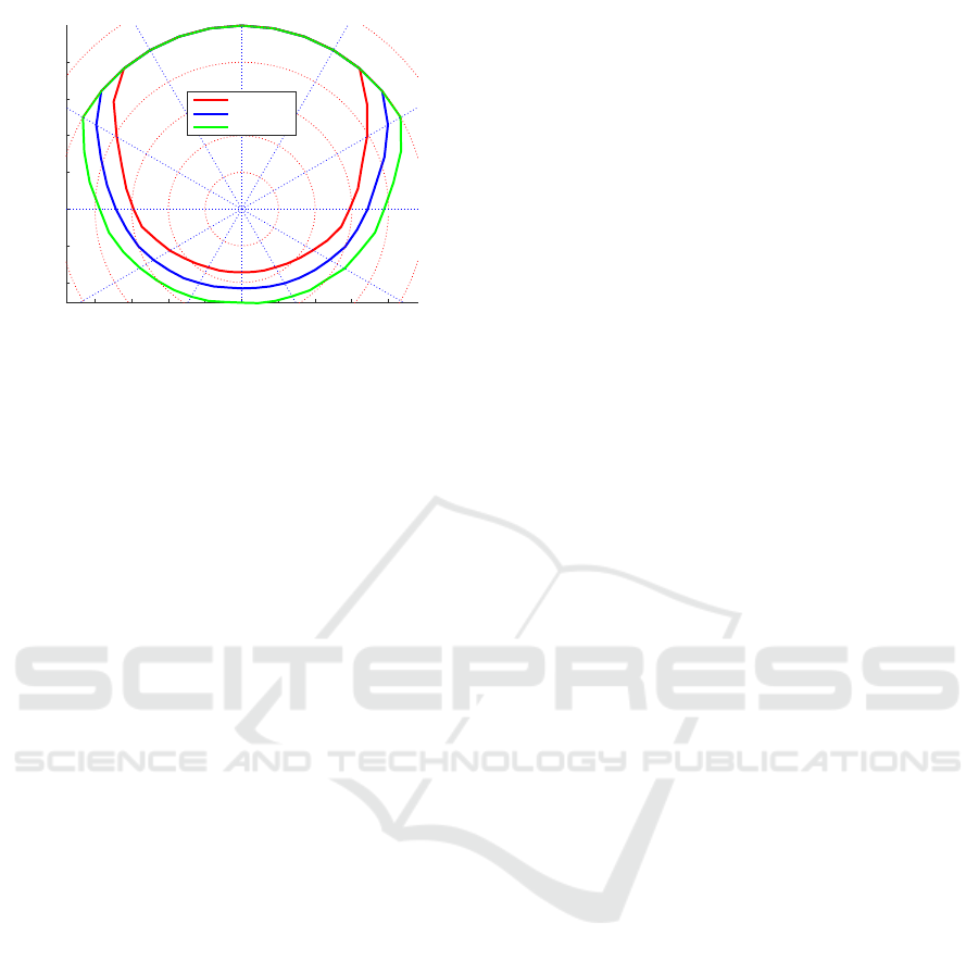
compared. Figures associated with Rmin computa-
tions can conclude that improved structural loading
or control power in terms of allowable g’s Fig. (4) and
seeker track rates Fig. (9) gives close combat advan-
tage to the pilots. On the other hand, designer can
choose moderate values of missile mass, diameter,
thrust and seeker look angles as elaborated through
Fig. (5) for close combat missions.
Influence of critical sub-systems for Rmax com-
putations are elaborated through Fig. (6). Figures as-
sociated with Rmax computations can conclude that
improved aerodynamic, propulsion and seeker look
angles can provide long range combat advantages to
the pilots. Moderate values of missile mass and con-
trol power in terms of allowable g’s are sufficient for
East (Feet)
× 10
4
-3 -2 -1 0 1 2 3 4 5
North (feet)
× 10
4
-3
-2
-1
0
1
2
3
Critical Sub-systems to Rmax
CRM-300
STR22
SLA30
Dia7In
RefThrust*1.3
Ref
Figure 6: Sub-systems more sensitive to Rmax computa-
tion.
East (Feet)
× 10
4
-2 -1 0 1 2 3 4
North (feet)
× 10
4
-2.5
-2
-1.5
-1
-0.5
0
0.5
1
1.5
2
2.5
Less Critical Sub-systems to Rmax
Max10g
RefMass*1.3
Ref
Figure 7: Sub-systems less sensitive to Rmax computation.
long range attack scenarios Fig. (7).
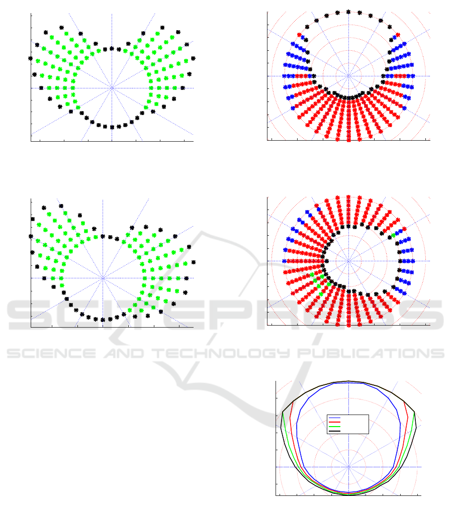
The Rmin sub-system limitation in the form of fre-
quency distribution against the stationary target and
moving target is shown in Fig. (8) and Fig. (9) respec-
tively. Green pattern which reflects the missile seeker
track rate limitation, shows the major limitation in
Rmin computations. Black pattern is the indication
of missile hit once seeker track rate is enough to track
the close range target. This distribution clearly indi-
cates that in close combat, seeker track rate is one of
the dominant element to consider.
Similarly, Rmax sub-system limitation in the form
of frequency distribution against the stationary target
and moving target is shown in Fig. (10) and Fig. (11)
respectively. Red pattern reflects the missile energy
Research on the Mission Critical Parameters Identification by using Kinematic Boundaries
649
East (Feet)
-3000 -2000 -1000 0 1000 2000 3000
North (Feet)
-2000
-1500
-1000
-500
0
500
1000
1500
2000
2500
3000
Rmin Critical Parameter Analysis
Figure 8: Critical sub-systems in Rmin against stationary
targets.
East (Feet)
-2000 -1000 0 1000 2000 3000
North (Feet)
-1500
-1000
-500
0
500
1000
1500
2000
2500
3000
Rmin Critical Parameter Analysis
Figure 9: Critical sub-systems in Rmin against maneuver-
ing targets.
limitation required to perform the hard turns in termi-
nal engagements. This energy requirement is in terms
of minimum closure rate V
t
−V
m
allowed once rocket
motors expires. Another dominant section is the mis-
sile seeker look angle constraint. Black pattern is the
indication of missile hit when is meets the required
evaluation criteria see Tab. (2). Hence, it can be stated
that rocket motor and seeker look angles are the pri-
mary parameters in long range missile designs.
Relative frequency of evaluation criteria in case of
missile fly-out termination is listed in Tab. (5). This
table shows the detailed operational evaluation of
missile against maneuvering target at different speeds
and altitude. Reference missile terminal energy and
seeker look angle limits the longer kinematic ranges.
Thus for long range engagements, missile propulsion
and seeker look angles characteristics can not be un-
dermined.
As mentioned before in Sec. (3.2.6) missile launch
tactics plays significant role in mitigating the design
challenges. Increase in the launch aircraft speed and
altitude enhance missile long range kinematic capa-
East (Feet)
× 10
4
-6 -4 -2 0 2 4 6
North (Feet)
× 10
4
-4
-3
-2
-1
0
1
2
3
4
Rmax Critical Parameter Analysis
Figure 10: Critical sub-systems in Rmax against stationary
targets.
East (Feet)
× 10
4
-6 -4 -2 0 2 4 6
North (Feet)
× 10
4
-4
-3
-2
-1
0
1
2
3
4
Rmax Critical Parameter Analysis
Figure 11: Critical sub-systems in Rmax against maneuver-
ing targets.
East (Feet)
×10
4
-4 -3 -2 -1 0 1 2 3 4
North (feet)
×10
4
-1
0
1
2
3
4
Msl Vel m/s=200 ,Tgt Vel m/s=200 ,T(g)=0
Rmax-M5kf-T5kft
Rmax-M10kf-T5kft
Rmax-M15kf-T5kft
Rmax-M20kf-T5kft
Figure 12: Rmax variation with altitude.
bilities. Increase in Rmax of reference missile Tab. (3)
is possible through increasing relative speed and alti-
tude w.r.t the target. Advantages associated with rel-
ative initial geometry are shown in Fig. (12) and ve-
locity Fig. (13). Such type of tactical remedies may
overcome the design limitations.
ICINCO 2017 - 14th International Conference on Informatics in Control, Automation and Robotics
650
East (Feet)
× 10
4
-4 -3 -2 -1 0 1 2 3 4
North (feet)
× 10
4
-2
-1
0
1
2
3
4
Msl Alt kft=10 ,Tgt Alt kft=10 ,T(g)=0
Msl200Tgt200
Msl300Tgt200
Msl400Tgt200
Figure 13: Rmax variation with speed.
5 CONCLUSIONS
Identification of mission critical parameters is very
imperative to meet user requirements. The utility of
automated tools based on the system mathematical
behaviour is necessary to meet iterative design pro-
cesses. By incorporating operational scenarios, these
evaluation models becomes more efficient. Techni-
cal challenges associated with finalizing system spec-
ification can be overcome by utilizing remedial tac-
tics. Missile system is being evaluated through devel-
oping kinematic model against highly agile targets.
Missile seeker, propulsion and structural loading or
control power are the key sub-systems to be evalu-
ated. Individual impact of each sub-system is care-
fully examined in an operational environment. Iden-
tification of mission critical parameters are proposed
through relative frequency distributions. Sub-system
design limitations are overcome through highlighting
missile launch strategies. It is concluded that missile
seeker track track rate greatly influence close combat
situations. Long range combat advantage is possible
through improved propulsion and seeker look angle
limit.
In future, adversary’s missile dynamics can be in-
cluded in friendly missile kinematic model, to high
light those parameters that can provide situational ad-
vantage in one-to-one air combat scenarios.
ACKNOWLEDGEMENTS
This research was supported by the National Science
Foundation of China under Grants 61502391.
REFERENCES
Chang Xiaofei, Yang Tao, Y. J. W. M. (2012). Design and
integration of hardware-in-the-loop simulation system
for certain missile. In Communications in Computer
and Information Science, volume 327–2, pages 229–
237.
Dawn Horn, Phil Colvert, B. S. (1997). Thaad integrated
system effectiveness simulation (tises). In American
Institute of Aeronautics and Astronautics. American
Institute of Aeronautics and Astronautics, Inc.
James M. Davies, J. F. R. and Oxtoby., N. P. (2011). Track-
ing system to maximize the engagement envelope of
a data linked weapon. In Signal Processing, Sensor
Fusion, and Target Recognition, volume 8050. Proc.
of SPIE.
Kascha Christian, T. C. (2015). Simple identification and
specification of cointegrated varma models. Journal
of Applied Econometrics, 30–4:675–702.
Kilian James C, S. T. M. (2016). Architecture and system-
of-systems design for integrated missile defense. In
Systems of Systems Engineering Conference. Institute
of Electrical and Electronics Engineers Inc.
Lin Chin-Yew, Xue Nianwen, Z. D. H. X. F. Y.
(2016). Natural Language Understanding and Intelli-
gent Applications, volume 10.1007/978-3-319-50496-
4. Springer-Verlag.
Michael, D. (2015). Probability and relative frequency.
Foundations of Physics.
Moore, J. (2015). Pragmatism, mathematical models and
the scientific ideal of prediction and control. Be-
havioural Processes, 114:2–13.
Roehm Tobias, Bruegge Bernd, H. T.-M. P. B. (2013). To-
wards identification of software improvements and
specification updates by comparing monitored and
specified end-user behavior. In International Confer-
ence on Software Maintenance, pages 464–467. Insti-
tute of Electrical and Electronics Engineers.
Ronghui Zhan, Shengqi Liu, J. Z. (2012). Improved target
tracking with aspect angle information. In IET Inter-
national Conference on Information Science and Con-
trol Engineering. Institution of Electrical Engineers.
Storrle, H. (2015). Cost-effective evolution of research pro-
totypes into end-user tools: The mach case study. Sci-
ence of Computer Programming, 134:47–60.
Vergez, P. L. (1998). Tactical missile guidance with pas-
sive seekers under high off-boresight launch condi-
tions. Journal of Guidance, Control and Dynamics,
21–3:465–470.
Yi Ping, Cheng Gengdong, X. L. (2014). Efficient algorithm
for probability-based design optimisation of complex
structures and related issues. Structure and Infras-
tructure Engineering Maintenance Management Life-
Cycle Design and Performance, 10–10:1264–1275.
Z. Kalogiratou, Th. Monovasilis, T. S. (2010). New mod-
ified rungekuttanystrm methods for the numerical in-
tegration of the schrdinger equation. Computers and
Mathematics with Applications, 60–6:1639–1647.
Research on the Mission Critical Parameters Identification by using Kinematic Boundaries
651
