
A Multivariable Self-tuning Controller for a D-type Water Tube
Industrial Boiler
Soroush Rastegarpour, Anacleto Petretti, Yasaman Ghanizadeh and Luca Ferrarini
Dipartimento di Elettronica, Informazione e Bioingegneria, Politecnico di Milano,
P.za L. da Vinci 32, 20133 Milano, Italy
Keywords: D-type Drum Boiler, Self-tuning Regulators, Model Identification, Pressure Control, Level Control.
Abstract: The present paper focuses on the development of a control system strategy on medium size industrial boilers
(up to 1 MW) with the aim of having safe and efficient operation for the boiler itself. The class of the
considered boiler is D-type water tube boiler. The basic plant model is based on Åström and Bell nonlinear
dynamic model with simple adaptation due to specific geometries and physical constraints. The control system
is mainly a combination of a pressure control loop and a three-element level controller. The pressure control
loop here proposed consists of a gain scheduling PID control strategy to operate on heat power in order to
keep the pressure at its desired value. The three-element level controller is a two-loop cascade control with
feed forward water aimed at correcting the mismatch between the demand (steam flow) and feed water flow:
level variation must be considered during this process because of the non-minimum phase behaviour of the
level. Due to switching behaviour of gain scheduling approach, an adaptive control rule is also investigated
in order to simplify the overall control structure and alleviate the adverse effects of the switching among many
controllers in industrial applications.
1 INTRODUCTION
Steam has unique properties that are extremely
important in many industrial processes, for a wide
variety of completely different applications. It can be
used to produce electricity but it can be directly used
in industrial processes for specific thermos-physical
transformation or for cleaning. Steam is basically
recycled, in a closed loop, from steam to water and
then back to steam again, all in a manner that is
nontoxic in nature. One of the most effective
parameters on ultimate cost of the end product is the
amount of heat required to produce the steam. This
heat must come from an energy source, and this varies
significantly, often based on the plant’s location in the
world (Everett B.Woodruff, 1998).
A boiler, or steam generator, is a closed vessel in
which water, under pressure, is transformed into
steam by the application of a suitable amount of heat.
to the references (Michael C. McGoodwin, 2016) and
(W.M. Rohsenow, J.P. Hartnett, Y.I. Cho, 1998) are
perfect sources to understand all the thermodynamics
concepts that are required in the present paper.
The first step before starting any procedure is to
have a description of the physical system. In this case,
a nonlinear dynamic model of the generic plant is
obtained. The most well-known nonlinear dynamic
control-oriented model for this kind of boilers is by
Åström and Bell model. The “Drum- boiler
dynamics” of Åström and Bell (K.J. Åström, R.D.
Bell, 2000) is a fundamental corner stone almost of
any studies in this field since it is a perfect
combination fidelity and simplicity.
The goal of this work is to develop a control
strategy to tackle the moderately complex non-linear
model that captures the key dynamical properties of
the steam drum boiler over a wide operating range
(K.J. Åström, R.D. Bell, 2000).
In order to improve plant performance and
flexibility as well as to reduce commissioning times,
nowadays, the trend is to exploit a reliable simulation
to design advanced control systems.
It may seem surprising that a traditional controller as
simple as PID controller can behave well enough, at
least so far (K.J Astrom, Tore Hagglund, 1995).
However, the market needs impose to improve
performance ever and ever.
As shown in (F.Morilla, march 2012), there is an
extensive works ongoing with boiler pressure and
level control systems. Mainly, they have been built up
Rastegarpour, S., Petretti, A., Ghanizadeh, Y. and Ferrarini, L.
A Multivariable Self-tuning Controller for a D-type Water Tube Industrial Boiler.
DOI: 10.5220/0006479203650372
In Proceedings of the 14th International Conference on Informatics in Control, Automation and Robotics (ICINCO 2017) - Volume 1, pages 365-372
ISBN: 978-989-758-263-9
Copyright © 2017 by SCITEPRESS – Science and Technology Publications, Lda. All rights reserved
365
as combination of conventional single variable
control loops and computation of variables that
cannot be measured directly (Balchen & Mumme,
1988). Advanced control techniques have also been
proposed to improve the performance of the control
system in comparison of a decentralized one (Tan, et
al., 2004). More complex and robust methodologies
such as LQG/LTR, H∞-control, predictive control,
and fuzzy control, have been also applied to improve
boiler performance (Tan, et al., 2005) in specific
cases. Based on (Sanjoy Kumar Chakraborty,
Nilotpal Manna and Surodh Dey, April 2014) the
importance of three-elements boiler drum level
control has been presented. From (Keyur Solanki,
Jalpa Shah, Nishith Bhatt, 2014), we can also prove
previous assumption on the level control scheme
based on the 3-element controller.
In this paper an adaptive control strategy will be
proposed to cope with nonlinearity of the boiler while
regulating its process characteristics on the desired
value. The whole procedure is done based on the
following pillars. First, a mathematical description is
provided through a nonlinear model for steam drum
of a D-type water tube boiler with natural circulation.
The model is derived from first principle modelling
method and is based on physical principles and
construction data. To validate the model, some real
data from a specific boiler have been considered and
used to tune the mdoel according to the classic grey-
box approach. Second, to compensate the
nonlinearities of the model, we divide the whole
operating range into several smaller ranges where the
process can be approximated by linear models. By
using system identification techniques, it is possible
to obtain many black-box models of the system,
linearized around various working conditions. Each
black-box model is only valid closed to its
corresponding operating point. Then, a specific
controller (a PID for compliance with the market) is
designed for each working point. Finally, two
adaptive techniques have been conveived and tested:
a gain-scheduling one and an adaptive one based on
interpolation approaches.
2 MODEL DESCRIPTION
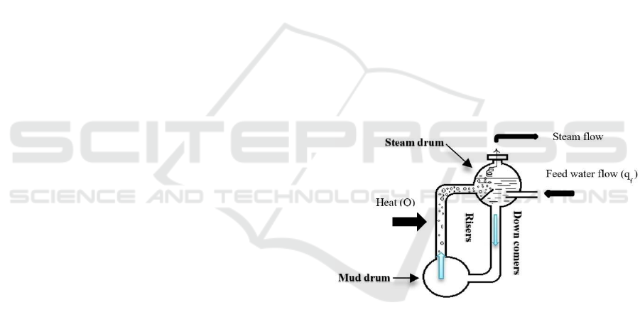
2.1 D-type Water Tube Boiler
As a general working principles of D-type water tube
boiler, tubes are used to convey water and steam
through the boiler. The combustion gases flow pass
the outside surfaces of the tubes. The simplified
sketch of D-type water tube boiler configuration is
shown in Figure1. This boiler consists of a series of
tubes and two drums (upper and lower ones). Drums
distribute water to the tubes and these water tubes
connect the drums and form a wall around the
combustion area, where the heat is generated. Water
is transferred into the upper drum through a feed
water inlet line. The water tubes which is called
‘down comers’ and the lower drum is filled
completely with water and the upper drum is only
filled with water to a certain level to provide space for
the steam. The upper drum is called ‘steam drum’. As
fuel is burned in combustion area, heat is transferred
to the adjacent tubes named ‘risers’. Water circulate
from steam drum through down comers and into the
lower drum.
Lower drum is referred to as the ‘mud drum’.
From mud drum, water is distributed to the risers
surrounding the combustion area. Water in risers is
heated and steam-water mixture is produced and
enters the steam drum. Steam is separated from water
and goes to the steam outlet and eventually into the
plant.
Steam drum has a very complex mechanism and
it has a tricky behaviour. In this project, the main
focus is on the designing the suitable control system
for steam drum.
Figure 1: D-type water tube boiler.
2.2 Nonlinear Dynamic Model of Steam
Drum Boiler
A key property of boilers is that there is a very
efficient heat transfer due to boiling and
condensation. All parts of the system which are in
contact with the saturated water-steam mixture will
be considered in thermal equilibrium. Energy stored
in steam and water is released or absorbed very
rapidly when the pressure changes. This mechanism
is the key for understanding boiler dynamics. The
rapid release of energy ensures that different parts of
the boiler change their temperature in the same way
(K.J. Åström, R.D. Bell, 2000).
ICINCO 2017 - 14th International Conference on Informatics in Control, Automation and Robotics
366

The model is derived from first principles of
thermodynamics laws, and is characterized by a few
physical parameters (K.J. Åström, R.D. Bell, 2000).
Variables subject to conservation laws are (Cooper,
2005): mass, energy and momentum.
Balance equations are then created by defining a
boundary around the process.
Note that level, temperature and process variables
other than those listed above are not conserved.
2.3 Mathematical Model
This section follows the Åström and Bell model
which is a nonlinear dynamic model for steam drum
of D-type water tube boiler with natural circulation.
By considering the schematic view of boiler in
Figure 1, let the main inputs be heat flow to the
system (Q), feed water mass flow rate (q
f
) and steam
mass flow rate (q
s
). Moreover, let the outputs be drum
pressure (P) and level variation (L).
Since first-principles dynamic model results from
the conservation equations, the balance equations are:
The global mass balance:
The global energy balance:
By substituting the internal energy ‘u’ with u=h-
, the global energy balance can be written as:
This equation represents the energy flow to the
system from fuel and feedwater and the energy flow
from the system via steam.
The total volume of the drum, down comers and
risers which is a constant value is:
By combining these equations with saturated
steam tables yields a simple boiler model which
describe only the behaviour of the drum pressure P to
manipulations of the inputs heat, feed water flow rate
and steam flow rate. But it cannot capture the
behaviour of the drum level. Eventually a model must
be obtained not only describe the behaver of the
pressure in the drum but also describe the distribution
of steam and water in the system.
The final form of model in format of state
equations are as below:
Where the coefficients e
ij
are as follows:
In addition, steam table are required to evaluate
h
s
, h
w
, ρ
s
, ρ
w
, t
s
, and partial derivatives with respect to
pressure at saturated pressure P.
The Table 1 and Table 3 summarize all the
parameters and their definitions.
Table 1: Parameters definition of the boiler.
Parameters
Definition
q
s
Steam mass flow rate
q
f
Feed water mass flow rate
q
sd
Steam flow rate through the liquid
surface in drum
q
dc
Down comer flow rate
q
cd
Condensation flow rate
q
ct
Total condensation flow rate
Q
Heat flow rate to risers (heat
supplied to the tubes)
V
t
Total volume
V
st
Total volume of steam
V
wt
Total volume of water
e
11
dV
wt
dt
+e
12
dP
dt
=q
f
q
s
e
21
dV
wt
dt
+e
22
dP
dt
=Q +q
f
h
f
q
s
h
s
e
32
dP
dt
+e
33
d
r
dt
=Q
r
h
c
q
dc
e
42
dP
dt
+e
43
d
r
dt
+e
44
dV
sd
dt
=
s
T
d
V
sd
°
V
sd
+
h
f
h
w
h
c
q
f
e
11
=
w
s
e
12
=V
st
s
P
+ V
wt
w
P
e
21
=
w
h
w
s
h
s
e
22
= V
st
h
s
s
P
+
s
h
s
P
+ V
wt
h
w
w
P
+
w
h
w
P
V
t
+ m
t
C
P
t
s
P
e
32
=
w
h
w
P
r
h
c
w
P
1
v
V
r
+
h
c
1
r
s
P
+
s
h
s
P
r
V
r
+
s
+
r
w
s
h
c
V
r
v
P
V
r
+ m
r
C
p
t
s
P
e
33
=
1
r
s
+
r
w
h
c
V
r
v
r
e
42
=V
sd
s
P
+
1
h
c
s
V
sd
h
s
P
+
w
V
wd
h
w
P
V
sd
+ V
wd
+m
d
C
p
t
s
P
+
r
1+
V
r
v
s
P
+
1
v
w
P
+
s
w
v
P
e
43
=
r
1+
V
r
s
w
v
r
e
44
=
s
A Multivariable Self-tuning Controller for a D-type Water Tube Industrial Boiler
367
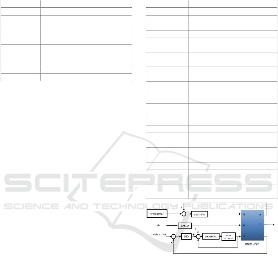
Table 2: Parameters definition of the boiler (cont.).
Parameters
Definition
V
wt
Total volume of water
V
sd
Volume of steam under the liquid
level in the drum
V
wd
Volume of water under the liquid
level in the drum
V
sd
◦
Volume of steam in drum in
hypothetical situation when there is
no condensation of steam in drum
P
Pressure
m
t
Total mass of drum and metal tubes
Model assumptions are:
The two phases of the water inside the
system are in saturated thermodynamics
state everywhere.
There is an instantaneous and uniform
thermal equilibrium between water and
metal everywhere.
Steady state metal temperature is close to
saturation temperature and the temperature
differences are small dynamically.
In this model water has natural circulation.
3 GAIN SCHEDULING
CONTROL STRATEGY
Gain scheduling is a technique that deals with
nonlinear processes, process with time variations or
situations where the requirements on the control
change with the operating conditions. To use this
technique, it is necessary to find measurable
variables, called scheduling variables, that are well
correlated with changes in process dynamics.
This method is one possible scenario to design a
control system for drum boiler over the whole
operating conditions. A scheduling variable is first
determined. Its range is quantitated into a number of
discrete operating conditions.
The controller parameters are then determined by
automatic tuning when the system is running in one
operating condition. For each working point, as it has
been shown in Figure 2, there are 3 PID controllers,
one for pressure loop on which the pressure is control
by heat and two for the two loops cascade control for
controlling the level variations.
Therefore, for each working points the PID controller
have been designed with the help of corresponding
estimated linearized models based on the black box
identification methods.
Table 3: Parameters definition of the boiler.
Parameters
Definition
ρ
w
Specific density of water
ρ
s
Specific density of steam
t
Temperature
h
c
Condensation enthalpy
h
s
Specific enthalpy of saturated
steam
h
w
Specific enthalpy of saturated
water
u
Internal energy
C
P
Specific heat of metal
L
Drum level
L
w
Level variation caused by changes
of the amount of water in the drum
L
s
Level variation caused by steam in
drum
L
r
Length of the risers
L
dc
Length of the down comers
A
Cross section of tube
A
d
Wet surface
α
m
Steam-mass fraction
α
v
Steam-volume fraction
α
r
Steam quality at riser outlet
ζ
Normalized length coordinate
along the risers
T
d
Residence time of the steam in
drum
Figure 2: Drum-Boiler control scheme.
3.1 Model Linearization
In this section, eight different working points have
been considered which result in eight various models
from identification and linearization methods. Since
in a nonlinear system there are so many option for
choosing the intended points, for the predefined
system the equilibrium points are consider at different
value of heat Q and pressure P corresponding to their
nominal values.
The model has been validated in various
equilibrium points presented in Table 4.
ICINCO 2017 - 14th International Conference on Informatics in Control, Automation and Robotics
368
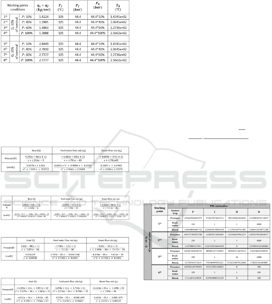
Table 4: Various equilibrium points for Drum-Boiler.
According to the strong interactions between the
inputs and outputs of the steam-drum boiler model
(Figure 2), a linear MIMO system should be
estimated in each working point.
In this paper, the first 4 working points are just
considered to implement the control strategies. In this
case, the linearized models for the first 4 working
points can be summarized in the Table 5, Table 6,
Table 7 and Table 8:
Table 5: Linearized MIMO system in the 1st working point.
Table 6: Linearized MIMO system in the 2nd working
point.
Table 7: Linearized MIMO system in the 3rd working point.
Table 8: Linearized MIMO system in the 4th working point.
3.2 Gain-Scheduling Implementation
for Warm-up Condition
According to the control scheme given in Figure 2,
three PID controllers for each working point are
needed as following:
Pressure loop PID controller
Level loop cascade control scheme
(including 2 PID controllers)
To sum up, by now four sets of PID controllers
have been designed. A very initial condition has been
defined for the real existing drum boiler used as a test
case, at which the boiler start to work from pressure
equal to 4 bar to its nominal value which is 44.4 bar.
The value of initial condition is arbitrary chosen and
it is better not to be close to the cold start up
condition, i.e. 0 bar for long time.
The first aim is to start from predefined initial
condition and reach the first working point as the first
set point. The first operating condition is considered
as the initial condition of the next stage to reach the
next operating work till the last operating point which
corresponds to the nominal pressure.
According to the gain scheduling approach, the
PID can be tuned as follows:
)1(
11
)(
p
G
G
GG
ss
N
ss
K
sPID
where K and N can be chosen to act on the velocity
of the control loop and
p
is a high-frequency pole for
the controller feasibility. In Table 9: Gain-scheduled
controller parameters tuned parameters in different
working points have been shown.
Table 9: Gain-scheduled controller parameters.
By applying the gain scheduling method and set point
scheduling, it can be demonstrated that whether each
set of controllers can work properly during their
operating conditions and automatically switch to the
next operating point when the pressure reaches the set
point value. Figure 3 shows the general definition of
this method.
As it can be seen in Figure 3, each set of
controllers works very well at their corresponding
working point. It means that the set point following
can be satisfied for the boiler model in nominal
pressure by implementing the gain-scheduled
A Multivariable Self-tuning Controller for a D-type Water Tube Industrial Boiler
369
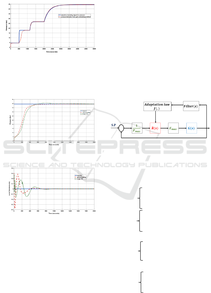
Figure 3: Drum pressure in different working points based
on gain scheduled controller.
controller. This method is compared with a single set
of PIDs for the same set point. Figure 4 and Figure 5
illustrate this comparison for pressure and level
control loops.
Figure 4: Gain-scheduled controller on drum pressure loop
(desired value: 44.4bar).
Figure 5: Gain-scheduled controller on drum variation level
loop (desired value: zero variation).
4 SELF-TUNING CONTROL
SCHEME
As it has been show in section 3, gain-scheduled
controller has better time domain characteristics, i.e.
faster, no overshoot and smother response. Although
it seems that gain-scheduled controller performs
numerically in a proper way, it will confront with
some limitation in practical application.
On the one hand, gain-scheduled method requires
a large effort to be implemented but when it combined
with auto-tuning, it will be very easy to use.
On the other hand, it will have adverse effects on the
industrial fields due to switching behaviour among all
controllers.
In this section, some interpolation approaches will
be used to design an adaptive function for each
control loop, i.e. pressure and level control loops.
In this case, the output of the system will be
filtered by a discrete filter to prepare an average value
rather than single one signal for the adaptive function.
After that the PID controllers will be retuned based
on the adaptive functions. The proposed adaptive
strategy is sketched in Figure 6 where
is the
maximum possible input for the boiler,
maximum output pressure, is the boiler dynamic
model and
is normalized controller.
Figure 6: Self-tuning control scheme.
Adaptive functions are designed based on the linear
interpolation of the given PID controllers in the gain-
scheduled method. So, the PID parameters will be
updated based on the following adaptive functions:
A. Pressure control loop
B. Level control loop – Outer loop
Derivative
gain
Integral
gain
Proportional
gain
Proportional
gain
ICINCO 2017 - 14th International Conference on Informatics in Control, Automation and Robotics
370
C. Level control loop – Inner loop
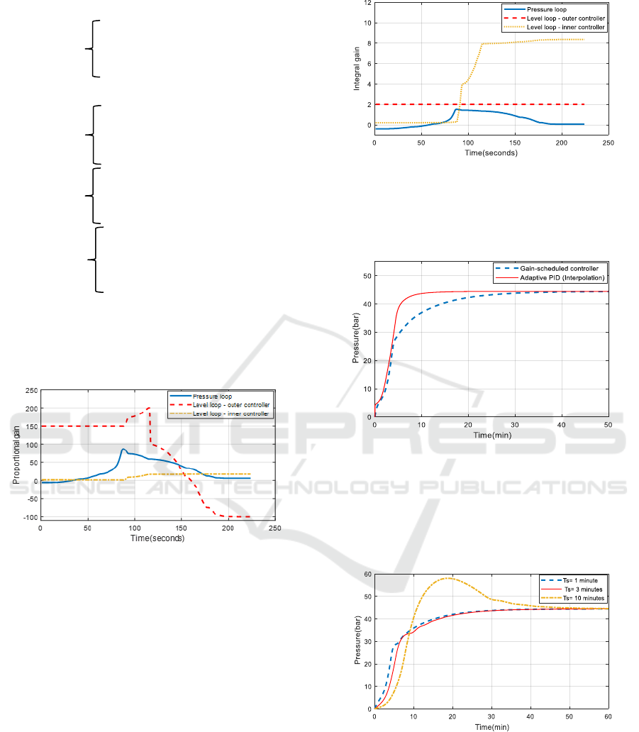
The PID coefficients profile have been shown in
Figure 7 and Figure 8. The updated PID is used in a
drum boiler initialized by 4 bar as the initial pressure
and 20 seconds as the filter time constant.
Figure 7: The PID coefficients profiles in adaptive control.
In this paper, a steam drum boiler endowed with a gain
scheduling control and an adaptive control scheme has been
considered for both control loops, i.e. pressure and level
control loops. As it has been shown in Figure 9 the gain
scheduled controller is a little bit faster, but as it mentioned
it has adverse effects in the practical application.
Simplicity, safety and accuracy are the most important
advantages of the self-tuning approach.
Figure 8: The PID coefficients profiles in adaptive control.
Although it is a bit slower than gain-scheduled
controller, it uses one adaptive PID controller rather
than a number of controllers.
Figure 9: Comparison between self-tuning controller and
gain-scheduled method.
Time constant of the filter is a crucial property of the
adaptive control scheme for boiler pressure control.
In Figure 10 the effects of different filter time
constant are evaluated.
Figure 10: Effect of filter time constant on pressure loop.
5 CONCLUSIONS
The aim of the paper is modeling and control of
medium-size industrial boilers (D-type water tube
boiler). Following the “Åström and Bell” model, a
Derivative
gain
Proportional
gain
Integral
gain
Derivative
gain
Integral gain: constant value equal to 2.
A Multivariable Self-tuning Controller for a D-type Water Tube Industrial Boiler
371

complex nonlinear dynamic model for natural
circulation of drum boilers has been derived. A real
drum boiler has been considered as a test case and the
model validated against the real case.
A single PID cannot cope easily with the system
nonlinear behavior.I It is more reasonable to extend
the number of working points and using the proper
controller for each linearized region. Each working
point has a set of PID controllers; one for pressure
loop and the other two for the two loops of the
cascade control based on the three elements level
control. Among all eight working points computed,
the first 4 have been chosen to represent the transient
behavior of the pressure till its nominal value.
Gain scheduling approach has been applied to
select the proper controller for each linearized model
in a discretized region. At the end an adaptive control
structure endowed by a linear interpolation function
has been considered to ease the control effort,
decrease the number of controllers and alleviate the
adverse effects of switching phenomena due to gain
scheduling methods. As it has been shown in the
simulation results, the implementation results had
satisfactory results.
Future directions include developing a better
tuning of the adapting technique (with more points
and finer interpolations) as well as integrating a more
complex decision rule. Also, robust control
techniques will be investigated.
REFERENCES
Balchen, J. G. & Mumme, K. I., 1988. Process Control:
Structures and Applications. New York: Van Nostrand
Reinhold.
Cooper, D., 2005. Practical Process Control. s.l.:Control
Station,Inc..
Everett B.Woodruff, H. B. T. F., 1998. Steam Plant
Operation. New York: McGraw-Hill.
F.Morilla, march 2012. Benchmark for PID control based
on the boiler control problem. brescia(Italy), s.n.
K.J Astrom, Tore Hagglund, 1995. PID controllers: theory,
design and tuning (2nd eddition). s.l.:instrument society
of america.
K.J. Åström, R.D. Bell, 2000. Drum-boiler dynamics.
automatica, 36(3), pp. 363-378.
Keyur Solanki, Jalpa Shah, Nishith Bhatt, 2014. Modeling
and Simulation of prototype of boiler drum level
control. IJMER(International Journal on Mechanical
Engineering and Robotics), 2(2).
Michael C. McGoodwin, 2016. engineering
thermodynamics, washington: s.n.
Sanjoy Kumar Chakraborty, Nilotpal Manna and Surodh
Dey, April 2014. Importance of three-elements boiler
drum level control and its installation in power plant.
International Journal of Instrumentation and Control
Systems (IJICS), 4(2).
Tan, W., Liu, J., Fang, F. & Chen, Y., 2004. Tuning of PID
controllers for boiler-turbine units. ISA Transactions,
43(4), pp. 571-583.
Tan, W., Marquez, H. J., Chen, T. & Liu, J., 2005. Analysis
and control of a nonlinear boiler-turbine unit. Journal
of Process Control, 15(8), p. 883–891.
W.M. Rohsenow, J.P. Hartnett, Y.I. Cho, 1998. hand book
of heat transfer. s.l.:McGrow-Hill companies.
ICINCO 2017 - 14th International Conference on Informatics in Control, Automation and Robotics
372
