Reduction of Mutual Coupling for UWB MIMO Antenna with a
Broadband Balance T-Line
Imtiaz Alam, Luqman Ali and Syed Asim Ali Shah
Department of Electrical Engineering, Bahria University, Shangrilla road, Sector E-8, Islamabad, Pakistan
Keywords: Mutual Coupling, Ultra-wide Band, Multiple-Input-Multiple-Output.
Abstract: A broadband balance T- type line is proposed to decrease the Mutual coupling of a smaller ultra-wide band
(UWB) multiple-performance Multiple-Input-Multiple-Output receiving antenna. With the decoupling
technique presented in this research, the UWB MIMO receiving antenna described covers the 3.1 – 9.4 GHz
band with a decoupling of more than 17 dBs. The proposed broadband balance T-line is actually set in the
margin area between two MIMO components and can be placed on the copper ground. A margin (radio
antenna range) of 20*10 mm2 is achieved. The UWB MIMO receiving antenna is simulated and S-
Parameters, radiation patterns are found to add productivity.
1 INTRODUCTION
MIMO (Multiple Input Multiple Output) antenna
arrays innovation has always been of interest for
researchers, due to its huge focal points of multitrack
decline and expansion of the channel capacity.
Almost all everyday gadgets, like PC, printers, and
cameras all include ultra-wide band MIMO radio
antennas which are connected to offer a high rate of
information within a short range.
The execution of radio antenna structure in a
compact device is influenced by the mutual
broadband coupling between the ultra-wide band
MIMO components. In addition, the improvement of
wideband segregation is an exceptional test problem,
particularly in the lower UWB band.
To date, several techniques have been introduced
for reducing mutual coupling of UWB MIMO
antenna. A parasitic element was placed between the
monopole elements (Zhang, et al., 2009). A capable
technique for mitigation of coupling effect was first
proposed by (Diallo, et al., 2006), while (Liu, et al.,
2013) applied different polarization with a metal
strip. The reduction of broadband mutual coupling
(Li, et al., 2015) Electro-Band Gap (EBG) were
etched on the ground plane, by using a metal stripped
with a circular disc inserted between UWB MIMO
antenna elements (Zhang & Pedersen, 2016).
However, the challenge to mitigate mutual coupling
effect with a predictable broadband line still exists.
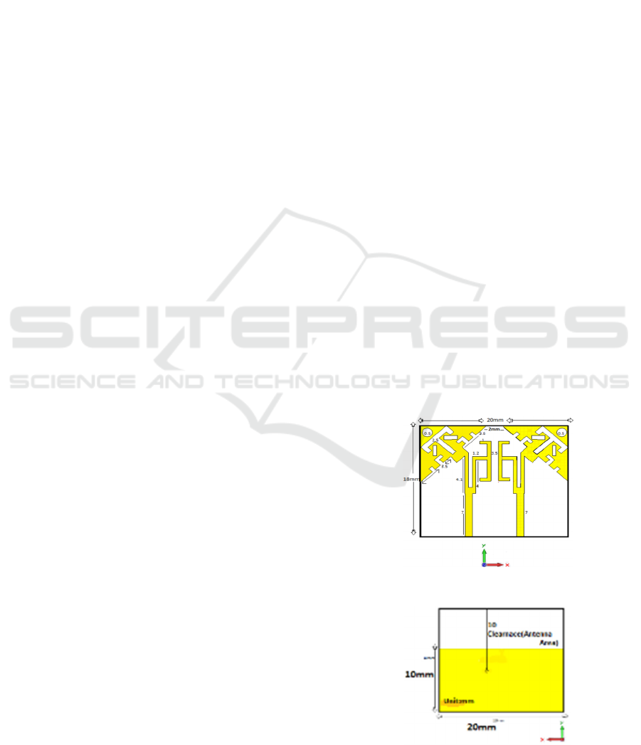
In this research, a T-type broadband line is used
between the two antenna elements for reduction of
coupling effects as shown in Figure 1a and Figure 1b.
The planned ultra-wide band antenna can cover the
frequency band 3.1 – 9.4 GHz with decoupling effect
of more than 17 dBs. The suggested T-type
neutralization line employed above the ground plane,
an antenna area of 20*10 mm2 acting as a small
clearance is achieved in the considered antenna.
Figure 1a: Geometrics of the Antenna.
Figure 1b: Geometrics of the Antenna.
Alam, I., Ali, L. and Shah, S.
Reduction of Mutual Coupling for UWB MIMO Antenna with a Broadband Balance T-Line.
DOI: 10.5220/0006483100930096
In Proceedings of the 14th International Joint Conference on e-Business and Telecommunications (ICETE 2017) - Volume 1: DCNET, pages 93-96
ISBN: 978-989-758-256-1
Copyright © 2017 by SCITEPRESS – Science and Technology Publications, Lda. All rights reserved
93
This technique helped the overall reduction in
mutual coupling and size of the antenna which can
improve the its performance, especially in the lower
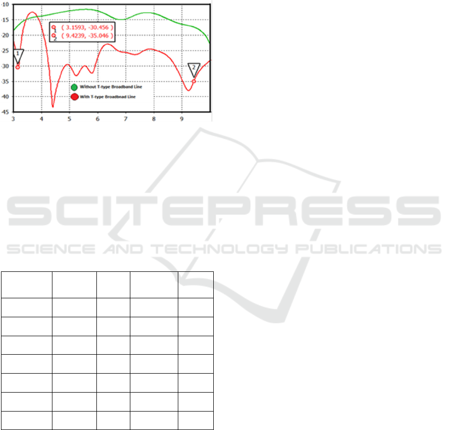
band. This research focuses on designing an antenna
using Computer Simulation Technology (CST) and
comparing S-parameters with and without T-type
broadband line with the existing antennas as shown in
Figure 2.
Figure 2: Simulated S-Parameters of ultra-wide band
MIMO antenna comparing without T-type broadband line
to with T-type broadband line.
S-parameters, far-field effect and size is compared with
existing UWB antenna with the recently designed antennas.
In this research, all numerical calculations are carried out
using CST (Studio, 2014). Table 1 shows different
parameters like width, length, radius and thickness of the
substrate feed line T-type broadband line.
Table 1: Different parameters of the substrate feed line T-
type broadband line.
Item Length Width Thickness Radius
Substrate 18mm 20mm 0.9mm -
Ground 10mm 20mm 0.028mm -
Feed Line 7mm 1.5mm 0.028mm -
Triangle 8.5mm - 0.028mm -
T-Line 3.5mm 1mm 0.028mm -
Circle - - 0.028mm 0.5mm
U-shaped 4.1&4mm 1mm 0.028mm -
The broadband line is composed of two metal strips that
are connected to T-type metal strips as shown in Figure 1,
which helped in the reduction of mutual coupling between
the antenna elements. The ground plane of the antenna with
no slot is composed of copper annealed (lossy metal). The
ground plane without any slot are composed of copper
annealed (lossy metal).
The S-parameters simulated in this work for the
proposed ultra-wide band MIMO radio antennas are given
in Figure 2. The intended MIMO receiving apparatus
covers the 3.1 – 9.4 GHz band with a shared coupling of
significantly less than 17 dBs. As a correlation, the
parameters without the broadband balance, the line is also
given, and with the planned decoupling system, the
segregation between two MIMO components of UWB can
be productively improved by 12 – 22 dBs. In addition, the
capacitance between the equilibrium line and the ground
will grow which is due to a substantial part of the
equilibrium line being above the ground plane.
Since the broadband balance line is associated with two
MIMO components, it will eventually marginally increase
the Q-element of the MIMO radio antenna components and
will somewhat decrease the data transfer capability.
(Zhang, et al., 2013). In any case, the transfer speed of the
proposed UWB MIMO cable can in any case effectively
cover the lower ultra-wide band of 3.1 – 9.4 GHz.
In general, due to high radiation capacity, the
connection between components of MIMO antennas are
low mostly when the antenna that receives MIMO operate
in a high, e.g. greater than 1.7 GHz, recurrence band.
(Vaughan & Andersen, 1987). While varying qualities in
the upper band, the aggregate efficiencies of the
components of the MIMO receiving apparatus are shown in
Figure 3 with the limits of execution of MIMO. The
proposed broadband balance line can effectively upgrade
disconnections between MIMO components so that the
aggregate productivity of the receiving ultra-wide band
MIMO antenna receives the possibility of advancement.
The addition reproduced to the efficiencies of the proposed
MIMO ultra-wide band receiving apparatus with a
broadband as well as without a broadband (NL) balance line
are shown in Figure 4.
The aggregate change of competition with the
broadband T-type line is clearly seen. It shows that even in
the large space between elements, the proposed dissociation
strategy can work productively.
To demonstrate the viability of decoupling, the current
allocations of the present MIMO ultra-wide band radio
antenna proposed with broadband balance line and without
a broadband balance line are shown in Figure 5. The current
allocations are gained when Port 1 (the MIMO component
on the left side as shown in Figure 3) is energized at 3.3, 4
and 4.7 GHz. The coupling current from port 1 when flows
towards port 2 in case of with broadband balance line can
suffocate significantly, which causes the lower common
couplings.
The current allocations at the rear of the proposed
MIMO UWB receiving apparatus at a frequency of 4 GHz
are given in Figure 3. Within the ground plane, the current
is extremely important. For different frequencies in the
range of 3.1 – 9.4 GHz, the currents are also important. In
fact, this region is used for radio frequency circuits, where
circuits affect the non-side in the execution of the receiving
cable. In this research, we have used it to establish the
encouraging link to diminish the impacts of the link in the
MIMO proposal that receives the execution of the cable.
DCNET 2017 - 8th International Conference on Data Communication Networking
94
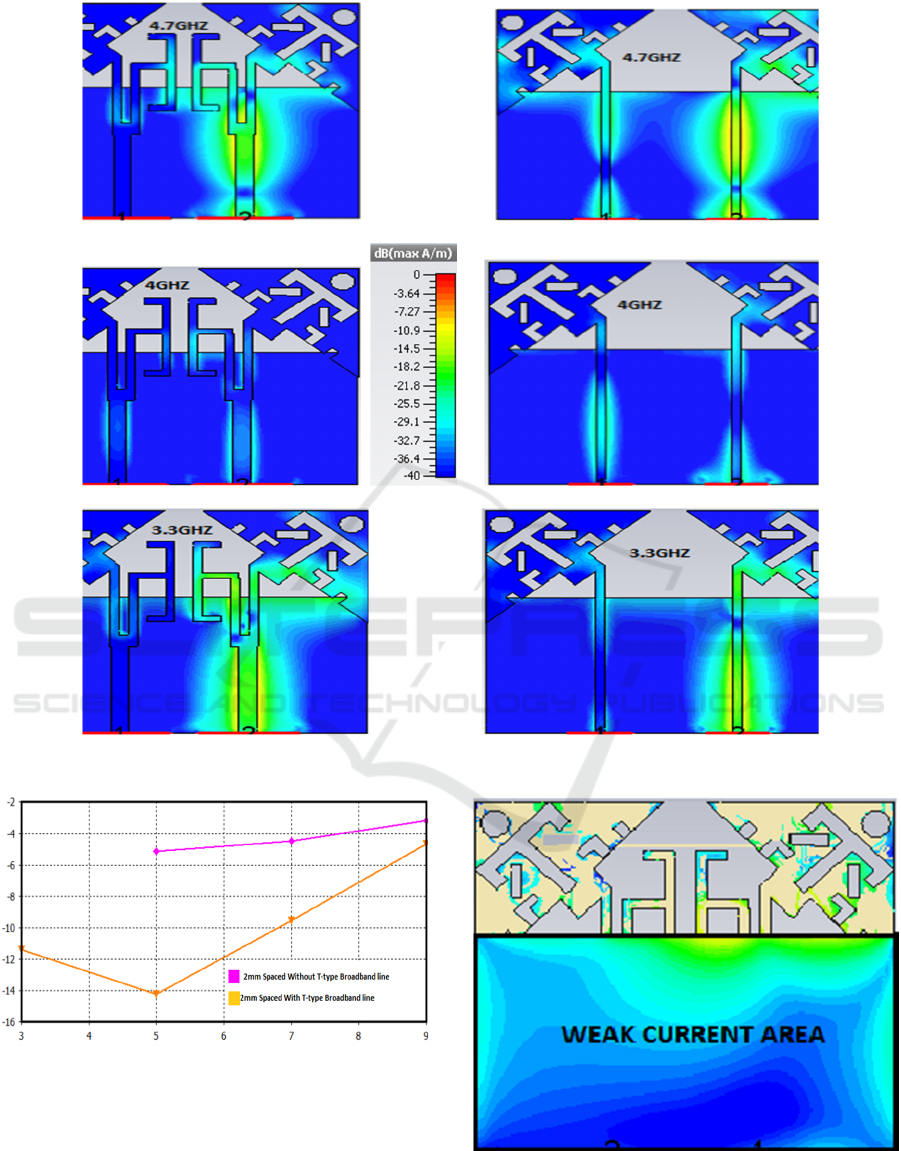
Figure 3: Proposed ultra-wide band MIMO Antenna current distributor with and without T-type broadband line.
Figure 4: Simulated total efficiency of proposed ultra-wide
band MIMO with and without T-type broadband Line.
Figure 5: Current distribution on Ground for proposed ultra-
wide band MIMO Antenna (colour slab is same as shown
in Figure 3).
Reduction of Mutual Coupling for UWB MIMO Antenna with a Broadband Balance T-Line
95

2 RESULTS
When comparing antenna’s area clearance, isolation in dB
and bandwidth in GHz for our introduced antenna versus
the existing antenna as shown in Table 2 below. It can be
observed that the antenna’s area clearance is the least,
isolation is average which is very good and the bandwidth
coverage is also from 3.1 – 9.4 GHz.
Table 2: Comparing antenna clearance, isolation and
bandwidth of proposed antenna with existing antennas.
Reference
Antenna Area
Clearance Size
mm2
Isolation
(dBs)
Bandwidth
(GHz)
(Zhang, et al.,
2009)
35*27.25 16 3.1-10.6
(Liu, et al.,
2013)
32*26 15 3.1-10.6
(Li, et al., 2015) 60*40 20 3-6
(Zhang &
Pedersen, 2016)
35*16 22 3.1-5
This work 20*10 17 3.1-9.4
3 CONCLUSIONS
In this research, an ultra-wide band Multiple Input Multiple
Output antenna has been designed which is smaller than
another previous antenna. It mitigates the coupling effect
more efficiently and covers a range of frequencies from 3.1
GHz to 9.4 GHz with the isolation of 17 dBs. The clearance
size area of proposed antenna is 20*10 mm2, this clearance
area is by far the least according to the current antennas
commercially available, which can be used in situations
where a small antenna is required. The current circulation
and parametric revision was explored and the decoupling
effect was removed from the new proposed T-Type as
compared to other previous design antenna in which the
broadband line exists.
REFERENCES
Diallo, A. et al., 2006. Study and reduction of the mutual
coupling between two mobile phone PIFAs operating in
the DCS1800 and UMTS bands. IEEE Transactions on
Antennas and Propagation, 54(11), pp. 3063-3074.
Li, Q., Feresidis, A. P., Mavridou, M. & Hall, P. S., 2015.
Miniaturized double-layer EBG structures for
broadband mutual coupling reduction between UWB
monopoles. IEEE Transactions on Antennas and
Propagation, 63(3), pp. 1168-1171.
Liu, L., Cheung, S. W. & Yuk, T. I., 2013. Compact MIMO
antenna for portable devices in UWB applications.
IEEE Transactions on Antennas and Propagation,
61(8), pp. 4257-4264.
Studio, C. M., 2014. Computer Simulation Technology.
[Online] Available at: http://www.cst.com
[Accessed 5 November 2016].
Vaughan, R. G. & Andersen, J. B., 1987. Antenna diversity
in mobile communications. IEEE Transactions on
vehicular technology., 36(4), pp. 149-172.
Zhang, S. et al., 2013. Reduction of the envelope correlation
coefficient with improved total efficiency for mobile
LTE MIMO antenna arrays: Mutual scattering mode.
IEEE transactions on antennas and propagation, 61(6),
p. 328.
Zhang, S. & Pedersen, G. F., 2016. Mutual coupling
reduction for UWB MIMO antennas with a wideband
neutralization line. IEEE Antennas and Wireless
Propagation Letters, Volume 15, pp. 166-169.
Zhang, S., Ying, Z., Xiong, J. & He, S., 2009.
Ultrawideband MIMO/diversity antennas with a tree-
like structure to enhance wideband isolation. IEEE
Antennas and Wireless Propagation Letters, Volume 8,
pp. 1279-1282.
DCNET 2017 - 8th International Conference on Data Communication Networking
96
