
A Model Compilation Approach for Optimized Implementations of
Signal-processing Systems
Andrea Enrici
1
, Julien Lallet
1
, Imran Latif
1
, Ludovic Apvrille
2
, Renaud Pacalet
2
and Adrien Canuel
2
1
Nokia Bell Labs France, Centre de Villarceaux, 91620 Nozay, France
2
LTCI, T
´
el
´
ecom ParisTech, Universit
´
e Paris-Saclay, 75013 Paris, France
Keywords:
Domain-specific Modeling, Model Transformation, Model-driven Architecture.
Abstract:
To meet the computational and flexibility requirements of future 5G networks, the signal-processing functions
of baseband stations and user equipments will be accelerated onto programmable, configurable and hard-
wired components (e.g., CPUs, FPGAs, hardware accelerators). Such mixed architectures urge the need to
automatically generate efficient implementations from high-level models. Existing model-based approaches
can generate executable implementations of Systems-on-Chip (SoCs) by translating models into multiple SoC-
programming languages (e.g., C/C++, OpenCL, Verilog/VHDL). However, these translations do not typically
consider the optimization of non-functional properties (e.g., memory footprint, scheduling). This paper pro-
poses a novel approach where system-level models are optimized and compiled into multiple implementa-
tions for different SoC architectures. We show the effectiveness of our approach with the compilation of
UML/SysML models of a 5G decoder. Our solution generates both a software implementation for a Digital
Signal Processor platform and a hardware-software implementation for a platform based on hardware Intel-
lectual Property (IP) blocks. Overall, we achieve a memory footprint reduction of 80.07% in the first case and
88.93% in the second case.
1 INTRODUCTION
Future 5G networks are expected to provide higher
data-rates (10x with respect to 4G) to support use
cases such as the Internet of Things (IoT) and cloud
computing (e.g., Cloud Radio Access Networks).
The equipment of current baseband stations is de-
signed with mixed architectures that contain both pro-
grammable (CPUs, Digital Signal Processors - DSPs)
and configurable (Field Programmable Gate Arrays -
FPGAs) components. To meet the computational re-
quirements of the above 5G use cases, the functions
(e.g., signal-processing operations) executed by both
components will change over time instead of being
statically allocated. This raises the need for unified
solutions capable to efficiently prototype designs of
5G mixed architectures.
Model-Driven Engineering (MDE) (Schmidt, 2006)
is widely accepted in the signal-processing domain
as the most promising design paradigm to cope with
these issues. MDE combines domain-specific model-
ing languages to abstract the structure, behavior and
requirements of a system under design, with transfor-
mation engines and generators. The latter analyze
models and produce artifacts such as source code,
simulation, verification inputs or alternative model
representations.
In the context of MDE for 5G Systems-on-Chip, an
important research problem is the efficient transla-
tion of system-level models — that abstract imple-
mentation details — into executable implementations.
Challenges arise from the desire to generate exe-
cutable code for different architectures (e.g., General-
Purpose Control Processors, FPGAs), implementa-
tions (i.e., software, hardware and mixed hardware-
software) and execution units (e.g., DSPs, CPUs,
Hardware Accelerators).
This paper proposes a compilation approach for
model-based specifications of SoCs, regardless of
their final realization technology (e.g., FPGA, Ap-
plication Specific Integrated Circuit - ASIC). Mod-
els are given as input to a model compiler that op-
timizes the system’s memory footprint and generates
ANSI C code for the memory allocation and schedul-
ing of signal-processing operations. As a practical
case study we propose the model-based design of a
5G datalink-layer decoder. The program compiled
from the decoder’s models is transformed into exe-
Enrici, A., Lallet, J., Latif, I., Apvrille, L., Pacalet, R. and Canuel, A.
A Model Compilation Approach for Optimized Implementations of Signal-processing Systems.
DOI: 10.5220/0006534800250035
In Proceedings of the 6th International Conference on Model-Driven Engineering and Software Development (MODELSWARD 2018), pages 25-35
ISBN: 978-989-758-283-7
Copyright © 2018 by SCITEPRESS – Science and Technology Publications, Lda. All rights reserved
25

cutable implementations for (i) a DSP-based platform
(software executable file) and (ii) a hardware IP-based
platform (FPGA bitstream) by a traditional software
compiler and a SoC design tool.
The rest of the paper is organized as follows. Sec-
tion 2 positions our work with respect to related con-
tributions. The structure of the compiler and its im-
plementation are respectively described in Section 3
and Section 4. Section 5 describes the model-based
design and compilation of the UML/SysML diagrams
for the 5G decoder. Section 6 concludes this paper
and discusses our future work.
2 RELATED WORK
In the context of UML-based MDE, code generation
for SoCs is based on a direct translation of UML
modeling assets into constructs of a target language
(e.g., a UML block becomes a C function), accord-
ing to precise translation rules (Vanderperren et al.,
2012). Many works propose one-to-one translation
rules for SoC languages such as C (Nicolas et al.,
2014), C++ (Ciccozzi et al., 2012), Verilog (Bazydlo
et al., 2014), VHDL (Moreira et al., 2010) and Sys-
temC (Mischkalla et al., 2010; Xi et al., 2005; Tan
et al., 2004). A representative work that uses one-
to-many translation rules is Gaspard2 (Graphical Ar-
ray Specification for Parallel and Distributed Comput-
ing) (Gamatie et al., 2008; DaRTteam, 2009), a MDE
SoC co-design framework based on MARTE (OMG,
2017). Thanks to the notion of Deployment, in Gas-
pard2 an Elementary Component (a resource or a
functionality in a MARTE model) is related to im-
plementation code that specifies low-level behavioral
or structural details in a usual programming language
(e.g., C/C++) for formal verification, simulation, soft-
ware execution and hardware synthesis.
Executable UML (xUML) or executable and translat-
able UML (xtUML) (Mellor and Balcer, 2003; Mel-
lor and Balcer, 2002) defines both a software devel-
opment methodology and a highly abstract software
language that combines a subset of UML’s graphical
notation with executable semantics and timing rules.
When ”programming” in xUML, a system’s applica-
tion is captured in the metamodel. The model com-
piler comprises some library code and a set of rules
that are interpreted against the metamodel to produce
text for a target SoC (e.g., C++ classes, C structs;
VHDL specifications for hardware registers). How-
ever, the overall architecture of the generated SoC is
defined by the model compiler itself (i.e., its trans-
lation rules). As opposed to our approach, xUML
considers a platform-independent model as only in-
put. To the best of our knowledge, no work exists that
attempts to optimize the performance of code gener-
ated from the xUML subset.
The Foundational Subset for Executable UML Mod-
els (fUML) (fUML, 2016) and the Action Language
for fUML (Alf) (Alf, 2017) standard were created to
make xUML models detailed enough and well spec-
ified for detailed programming and machine execu-
tion. The goal of fUML is to go beyond xUML in
specifying a reasonable subset of UML with a precise
semantics, in order not to be specific to any executable
modeling methodology. The syntax of Alf is bor-
rowed from Java, C, C++ and C# to specify the behav-
ior and computation (concurrent data-flow semantics)
of graphical fUML models. xUML, fUML and Alf
are essentially focused on specifying a semantics suit-
able to generate executable code from UML graphi-
cal models. With respect to this, our work goes one
step further. Our model compiler demonstrates that
non-functional properties of a system denoted with
UML/SysML diagrams can be improved before code
generation, with a significant impact on the perfor-
mance of the final executable (e.g., memory footprint
reduction).
In the 2011 edition of MODELS, the work in (Floch
et al., 2011) illustrated how MDE techniques (e.g.,
meta-metamodels, meta-tools, Domain Specific Lan-
guages) can be applied to help in solving or simpli-
fying issues such as code maintainability and sustain-
ability, interfacing with external tools, semantics pre-
serving of the Intermediate Representation transfor-
mations and code generation. While (Floch et al.,
2011) tries to bridge the gap between model-based
optimizations and abstract representations of pure
software systems, our work transforms system-level
models that also include hardware components (e.g.,
on-Chip RAM memories).
The landscape of industrial tools that generate SoC
implementations of signal-processing applications
from models is also very rich, e.g., National In-
struments LabVIEW Communications System De-
sign (Labview, 2017), MATLAB (MAtrix LABora-
tory) (Mathworks, 2017), GNU Radio (GNURadio,
2017). While our compilation approach targets multi-
processor architectures, these tools translate models
that describe the functionality of a system to be exe-
cuted onto single-processor architectures where data
are processed onto a single unit.
3 THE COMPILER STRUCTURE
The model compiler that we present in Fig. 1 takes as
input model-based specifications (a Platform-Specific
MODELSWARD 2018 - 6th International Conference on Model-Driven Engineering and Software Development
26
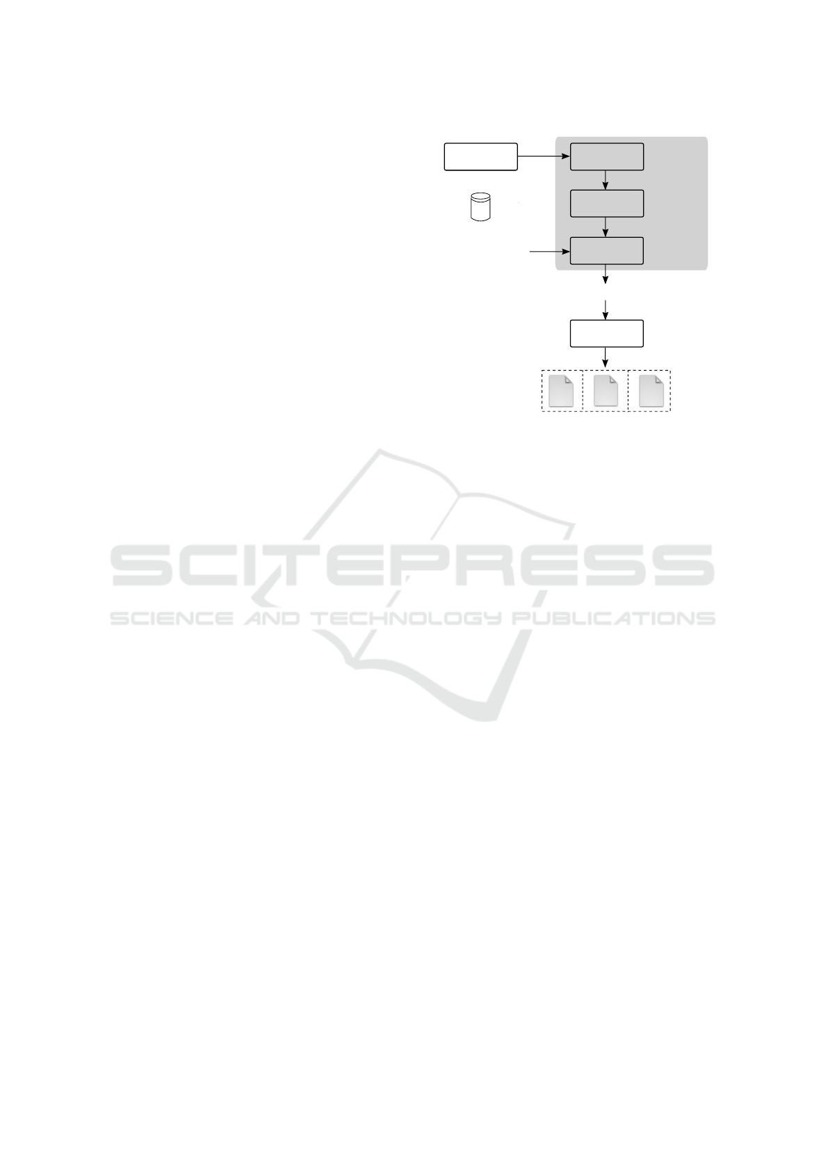
Model - PSM - and a Platform Independent Model -
PIM) from a MDE design environment and produces
an optimized program (Target program in Fig. 1).
Prominent examples of MDE environments used in
the signal-processing domain are described in (Ger-
stlauer et al., 2009). In these environments, a target
system is first modeled, then design alternatives
(PSMs) are explored until a solution that satisfies
the desired requirements (e.g., latency, throughput)
is found to be realized. It is this solution that our
compiler takes as input.
Our compiler in Fig. 1 is inspired by those for
traditional programming languages (Torczon and
Cooper, 2007). However, it differs from the latter in
mainly two aspects. First, it has two inputs: a pair
PIM-PSM and a library of implementation-specific
functions of the computation and communication
operations that are allocated in the PSM. Second,
our compiler operates at a higher abstraction level,
known as system-level (Gerstlauer and Gajski,
2002). The scale at which the compiler performs
optimizations is the one of an entire system (e.g.,
a Multi-Processor System-on-Chip) with multiple
computation, communication and storage units that
can be shared, distributed or both; rather than a
single processor (e.g., CPU, DSP). In analogy with
traditional compilers whose middle-end attempts
to optimize the allocation of CPU registers, our
system-level model compiler attempts to optimize the
allocation of buffers that store arrays of data in the
memories of signal-processing units.
The front-end is dedicated to “understanding” –
with scanning and parsing techniques – the PIM
and PSM denoted in a specific modeling lan-
guage (e.g., UML/SysML/MARTE (Gomaa, 2016),
AADL (Feiler and Gluch, 2012)) and to encode this
knowledge (e.g., topology of the target platform,
dependencies between functions, scheduling and
memory allocation constraints imposed by hardware
and software units onto the allocated functions)
into an Intermediate Representation (e.g., a directed
graph) IR1 in Fig. 1. IR1 must be independent of
the language used to denote the models. It must also
preserve their behavior.
The purpose of the middle-end is to attempt to
rewrite IR1 in a way that is more convenient to opti-
mize the performance of the final implementation in
terms of memory management, power consumption,
throughput, etc. Such a rewriting results in a second
intermediate representation (IR2) that must respect
the static allocation of functions defined in the PSM
(i.e., if function A has been allocated to unit U1, it
cannot migrate to another unit at run-time) and must
Scanner,
Parser
System-level
MDE design tool
System-level
optimizations
Front End
Middle End
Back End
Library of
implementation-specific
functions of
computation and
communication
operations
Code
generator
Target program
translator
Target program
Executable
hardware
implementation
IR2
IR1
Model
compiler
Executable
software
implementation
Executable
hardware-software
implementation
PIM,
PSM
Figure 1: The model compilation approach.
preserve the behavior present in IR1. Examples of
optimizations that can be performed at this stage are:
optimizations that reduce the memory occupancy of
storage units, scheduling optimizations that minimize
the workload of processing and communication units.
In Fig. 1, the back-end is a code generator that
translates IR2 into a target program written in a
high-level programming language (e.g., C/C++).
This program schedules the execution of computation
and communication operations and also manages the
allocation of the physical memory regions where data
are stored. The program is generated by including
a library of implementation-specific functions of
computation and communication operations. The
final target program must be behaviorally equivalent
to IR2, IR1 and the PIM-PSM.
The target program translator produces an exe-
cutable implementation. This can be a pure software
implementation (e.g., an application that runs on
top of an Operating System onto a general-purpose
control processor) or a pure hardware implementa-
tion (e.g., a hardware IP-based design) or a mixed
hardware-software implementation (e.g., some func-
tionalities are executed by a general-purpose control
processor and some are accelerated in hardware).
In the case of implementations that require some
functionality to be realized in hardware, the translator
is a Computer Aided Design (CAD) toolsuite (e.g.,
Xilinx Vivado High Level Synthesis). In case of
pure software implementations, the translator can be
a traditional programming-language compiler (e.g.,
A Model Compilation Approach for Optimized Implementations of Signal-processing Systems
27

GNU/gcc/g++, clang, TurboC). The lower part of
Fig. 1 (dotted boxes) represents all of these possible
implementation types.
The compiler proposed in Fig. 1 essentially performs
a series of model transformations: model-to-model
in the front-end and middle-end, model-to-text in
the back-end. These transformations should be
formally described in order to guarantee that the
output model/text of the transformation retains the
semantics of the input model. However, these formal
descriptions depend not only on the formalism of
the input PIM-PSM and on the language of the
output target program. They also depend on the
formalism of the Intermediate Representations. As
stated in (Floch et al., 2011): ”Since compiler IRs are
abstractions used to represent programs, they are by
essence models (an instance of IR is an abstraction of
the given source code). In this context, the grammar
of the source language, or more often the structure of
IR, becomes the metamodel”.
An implementation of the compiler architecture
shown in Fig. 1 results in a tool that can be used
to target, at the same time, different implementation
types for multiple architectures. Given the pair PIM-
PSM and a library of implementation-specific func-
tions, an implementation to be executed in software
(e.g., for execution on a control processor, for em-
ulation purposes) is obtained by using a traditional
compiler (e.g., GNU/gcc) for software languages. By
changing the translator to a CAD tool, the same sys-
tem can be realized in terms of both hardware and
software components (e.g., executable file and FPGA
bitstream). By changing the input models only, the
same tool-chain (i.e., input MDE environment, model
compiler, target program translator) and library of
implementation-specific functions can target different
signal-processing applications.
4 COMPILER
IMPLEMENTATION
In this section, we describe an implementation of
the model compilation approach in Fig. 1 that tar-
gets multi-processor Systems-on-Chip implementa-
tions for signal-processing applications.
4.1 Implementation Overview
The implementation of our compiler is shown in
Fig. 2. It is inspired by the code generation engine
Graph generator
TTool/
DIPLODOCUS
Memory
optimizer
Front End
Middle End
Back End
Configuration
file .hal
G = (A,E)
C program
generator
G' = (A',E')
MDE-to-compiler
scanner and parser
Target C program
UML-SysML
PIM, PSM
Library of
implementation
specific
functions
Figure 2: The implementation of the approach in Fig. 1.
in (Enrici et al., 2017), where the middle-end is ex-
tended with memory allocation optimizations.
4.2 Front-end
The front-end in Fig. 2 converts an input pair PIM-
PSM model into a first intermediate representa-
tion G = (A, E): a Synchronous Data Flow (SDF)
graph (Lee and Parks, 1995) annotated with map-
ping information. The models are parsed and scanned
by a MDE-to-compiler plugin that allows the com-
piler to be independent of the specific modeling
language used by the input MDE. In this paper,
the PIM-PSM is taken from the open-source MDE
framework TTool/DIPLODOCUS (Apvrille et al.,
2006; Apvrille, 2008). The plugin scans and
parses a PIM-PSM described in .xml format by
TTool/DIPLODOCUS and passes this description to
the Graph generator (Fig. 2).
In a SDF graph, nodes (actors) represent processing
entities interconnected by a set of First-In First-Out
(FIFO) data queues. An actor starts execution (fir-
ing) when its incoming FIFO(s) contains enough to-
kens, it cannot be preempted and produces tokens
onto its outgoing FIFO(s). The number of tokens con-
sumed/produced by each firing is a fixed scalar that
is annotated with the graph edges. As actors have
no state in the SDF Model of Computation (MoC), if
enough tokens are available, an actor can start several
executions in parallel. For this reason, SDF graphs
naturally express the parallelism of signal-processing
applications and can be statically analyzed during
compilation for memory allocation optimizations.
A PIM in DIPLODOCUS is a SysML Block Def-
inition diagram that captures the computation of a
signal-processing system as well as their data and
control dependencies. The internal behavior of each
operation is further described by a SysML Activity
diagram. At the highest level of abstraction, a SysML
MODELSWARD 2018 - 6th International Conference on Model-Driven Engineering and Software Development
28

Block Definition diagram can be seen as a graph
whose nodes are the SysML Blocks and the edges are
the SysML relations. Similarly, also a SysML Activ-
ity diagram can be seen as a graph where activies and
activity edges are equivalent to the graph’s nodes and
edges, respectively. As we are interested in optimiz-
ing the memory footprint of a signal-processing sys-
tem, we only consider blocks in the PIM that are con-
nected by data relations. Therefore, the IR generator
in Fig. 2 translates each SysML block that represents
a data-processing operation and each SysML data re-
lation into a SDF actor and edge, respectively. The
number of tokens associated to SDF edges is given by
the SysML Activity diagram that describes the inter-
nal behavior of SysML Blocks. Each actor in the re-
sulting SDF graph G is annotated with the execution
unit where is has been mapped in the PSM. A PSM
in TTool/DIPLODOCUS is a UML Deployment di-
agram that specifies a platform’s topology, its units
(e.g., CPU, Direct Memory Access - DMA, mem-
ory) and each unit’s performance characteristics (e.g.,
number of cores for a CPU, number of channels for a
DMA). UML artifacts map operations onto the plat-
form’s units.
4.3 Middle-end
In this version of the compiler’s middle-end, we
propose a system-level memory optimizer that min-
imizes the footprint of the logical buffers associated
with the data channels among computations in a
SysML PIM from DIPLODOCUS. In this work, we
differentiate between logical and physical buffers. A
physical buffer defines a range of memory addresses
of a physical memory device (e.g., a Random Access
Memory - RAM). A logical buffer, instead, is a
virtual address space that can be mapped onto one or
multiple physical buffers.
Our optimizer implements a variant of the allocation
techniques presented in (Desnos et al., 2014) that
we adapted to allow the sharing of input and output
buffers of actors, similar to one of the memory
reuse techniques presented in (Desnos et al., 2016).
Essentially, the optimizer performs a series of graph
transformations to deduce a lower bound for the
physical buffers that must be allocated for the PIM’s
logical buffers.
The SDF graph G in Fig. 2 is transformed first into a
single-rate SDF, where the production and consump-
tion rates on each FIFO are made equal. The single-
rate SDF is transformed into a Direct Acyclic Graph
(DAG) by isolating one iteration of the single-rate
SDF and by ignoring FIFOs with initial tokens. The
DAG graph contains two types of memory objects:
• Communication buffers that are used to transfer
tokens between consecutive actors.
• Feedback/pipeline buffers that store feedback FI-
FOs, i.e., buffers corresponding to (feedback)
edges whose input and output port are associated
with the same actor.
Our work differs from (Desnos et al., 2014) as, in
the latter, a DAG also expresses an estimation of
an actor’s internal memory (e.g., the stack space
of a task allocated by an Operating System). In
the context of our research, as 5G applications are
accelerated by hardware IP blocks, there is no need to
express the internal working memory of DAG actors.
From the DAG, a Memory Exclusion Graph (MEG)
is derived. Nodes in the MEG represent logical
memory objects: FIFO buffers whose size is equal to
the number of tokens in the single-rate SDF. Edges
in the MEG link logical FIFO buffers that cannot
be allocated to overlapping physical buffers. The
MEG is then updated with mapping information
from the PSM that specifies the execution constraints
(scheduling) for each signal-processing operation.
This allows to remove edges (exclusion relations)
between nodes in the MEG. The purpose of this
operation is to merge logical buffers so that physical
buffers in the executable code can share common
memory regions, thus reducing the total footprint of
an application.
At this point, the heuristics proposed in (Desnos et al.,
2014) is applied to compute a lower bound for the
memory of the physical buffers. This bound is defined
in (Fabri, 1979) as the weight of a Maximum Weight
Clique (MWC). A clique is a subgraph of MEG ver-
tices within which each pair of vertices is linked with
an edge. As the memory objects of a clique cannot
share memory space because they mutually exclude
each other, the weight of a clique gives a lower bound
to the amount of memory that must be allocated for
all of the clique’s buffers. This amount is equal to the
sum of the sizes of all clique’s buffers. The pseudo-
code of the heuristics proposed in (Desnos et al.,
2014) is shown in Algorithm 1.
In each iteration of the main loop (lines 6-13) in
Algorithm 1, minimum cost vertices v
∗
are removed
from C (line 8). If multiple vertices have the same
cost, the vertex v with the lowest number of neigh-
bors |N(v)| is removed. If the number of neighbors is
equal, then the vertex v with the smallest weight w(v)
is removed. If there are still multiple vertices with
equal properties, a random vertex v
random
is selected.
The loop iterates until the vertices in C form a clique.
This condition is verified, line 6, by comparing the
A Model Compilation Approach for Optimized Implementations of Signal-processing Systems
29

Algorithm 1: The MWC heuristics.
/* C = the clique */
/* nb
edges
= number of edges in C */
/* cost(·) = cost function of C */
/* v = generic vertex in C */
/* w(v) = weight of vertex v */
/* N(v) = neighbor vertices of v */
/* |N(v)| = lowest number of v’s
neighbors */
1 C ← V
2 nb
edges
← |E|
3 foreach v ∈ C do
4 cost(v) ← w(x) +
∑
v
0
∈N(v)
w(v
0
)
5 end
6 while |C| > 1 and
2·nb
edges
|C|·(|C|−1)
< 1.0 do
7 Select v
∗
f rom V that minimizes cost(·)
8 C ← C\{v
∗
}
9 nb
edges
← nb
edges
− |N(v
∗
) ∩C|
10 foreach v ∈ {N(v
∗
) ∩C} do
11 cost(v) ← cost(v) − w(v
∗
)
12 end
13 end
14 Select a vertex v
random
∈ C
15 foreach v ∈ {N(v
random
)\C} do
16 if C ⊂ N(v) then
17 C ← C ∪ {v}
18 end
19 end
edge density of a clique with the edge density of the
MEG subgraph formed by the remaining vertices in C.
The edge density of a clique is defined as the ratio be-
tween existing exclusions and all possible exclusions.
Such density is equal to 1.0 in the case of the complete
MEG. The number of edges, nb
edges
, is decremented
at line 9 by the number of edges in L that link the re-
moved vertex v
∗
to vertices in C. Lines 10-12 update
the costs of the remaining vertices for the next itera-
tion. The complexity of the heuristic algorithm is of
the order of magnitude of O(|V |
2
), where |V | is the
number of vertices of the MEG subgraph.
The lower bound computed with Algorithm 1 is anno-
tated to edges in G, resulting into graph G
0
, Fig. 2. It
provides an exact value for the size of physical buffers
that are allocated in the final executable. This is op-
posed to (Desnos et al., 2014), where the bound is
a theoretical value that depends on the estimation of
the internal working memory of DAGs’ actors. Con-
sequently, the MWC value in (Desnos et al., 2014)
must be verified before being used to allocate physi-
cal memory.
4.4 Back-end
The back-end in Fig. 2 translates G
0
into a C pro-
gram. Each actor (operation) in G
0
is translated into
3 C routines for initialization, scheduling and clean-
up purposes (Fig. 2). Initialization and clean-up rou-
tines are called once, when the program starts and ter-
minates, respectively. These routines manipulate the
software data structures that are needed by processing
units in the target platform to prepare and clean up the
execution of an actor in G
0
. Scheduling routines are
called to test the eligibility to run an operation
1
. Exe-
cution routines (implementation-specific functions in
Fig. 2) are added to each actor from an external li-
brary. They trigger the execution of an operation on
the hardware. The memory bound determined by Al-
gorithm 1 is used by the back-end to allocate shared
physical buffers for operations mapped to the same
execution unit.
In the current implementation of the compiler, the ex-
ecution routines must be manually written by a user
and are included in the final source code via a ded-
icated configuration file (.hal, hardware abstraction
layer file in Fig. 2). These execution routines spec-
ify, at a lower level of abstraction, the implementation
details (e.g., data structures) of the signal-processing
algorithms that are described, at system-level, by the
PIMS’s UML/SysML diagrams. Given the real-time
nature of the systems that we aim to program, it is
mandatory to specify these algorithms with a less ab-
stract language (i.e., C ) that offers constructs which
match more closely the characteristics of the underly-
ing hardware execution platform (e.g., memory align-
ment of struct fields to accelerate DMA transfers). In
analogy with the traditional programming of signal-
processing systems, where C programs embed as-
sembly code for functionalities that are time-critical
at instruction-level of abstraction, our UML/SysML
programs embed C code for functionalities that are
time-critical at system-level of abstraction.
4.5 Discussion
In this version of the model compiler, we did not in-
clude any environment for the analysis of the IRs’
metamodels as this goes out of the scope of our cur-
rent research interests. As described in (Floch et al.,
2011), techniques such as generative approaches,
model mapping, Domain Specific Languages and
metamodel instrumentation exist to guarantee the cor-
rectness and maintainability of IR transformations.
1
The target C program in Fig. 2 schedules operations
according to the availability of input data, coherently to the
SDF MoC.
MODELSWARD 2018 - 6th International Conference on Model-Driven Engineering and Software Development
30
However, due to scalability reasons, their use is dif-
ficult to apply to research compilers. It is, however, a
practically surmountable problem that can be solved
by developing additional features to the model com-
piler. In the context of the case study of Section 5,
we manually verified the equivalence between (i) the
data-flow relations in graphs G, G
0
, (ii) the data-flow
scheduling of operations in the target C program and
(iii) the data-flow dependencies in the input PIM.
4.5.1 Portability
This implementation of the model compiler addresses
platforms where the scheduling of operations is cen-
trally executed by a single general-purpose control
processor. The latter configures and dispatches the ex-
ecution of operations to a set of physically distributed
units (e.g., DSPs, DMAs, IPs), according to events
generated upon the consumption/production of data
by computation and communication operations. For
each platform, a dedicated library of implementation-
specific functions must be provided by re-using those
from other projects as templates. To target designs
where the control code of an application is frag-
mented into separate executables that each run onto
different CPUs, the compiler must be extended (e.g.,
produce multiple executables, include synchroniza-
tion primitives among multiple units).
In order to use this implementation of the compiler
with a design tool other than TTool/DIPLODOCUS,
the user needs to write a new plug-in for the front-
end. The existing plug-in can be used as a template to
reduce development efforts.
4.5.2 Debugging
In our compiler, debugging is done at different loca-
tions: in the front-end MDE tool, in the C target pro-
gram and the implementation-specific functions (e.g.,
Valgrind, gdb). Transformations of the Intermediate
Representations can be manually debugged by com-
paring the data-flow relations among SDF actors in G,
G
0
and those between SysML blocks in the input PIM.
Also, simulation and formal verification techniques in
the input MDE tool can be used to guarantee the cor-
rectness of the PIM and PSM with respect to design
requirements.
5 CASE STUDY
We used the model compiler described in this paper
to produce executable code for two target platforms,
from the UML/SysML model of a 5G decoder that
we designed in DIPLODOCUS for the uplink (SC-
FDMA), single antenna case, Physical Uplink Shared
channel (xPUSCH), based on (Verizon, 2015).
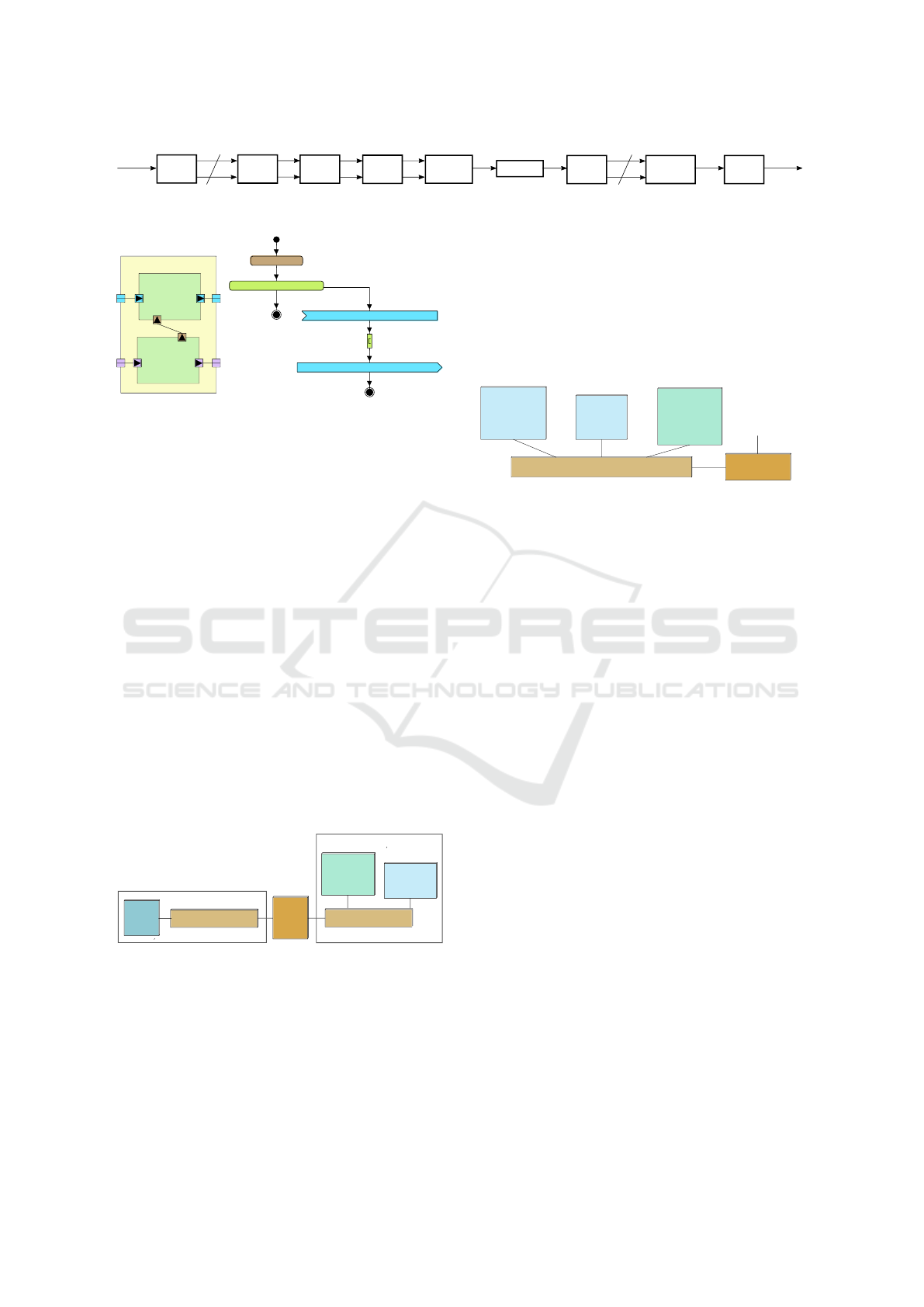
The algorithm of the signal-processing operations
(application) that compose the 5G decoder is shown
in Fig. 3. We captured this application in a
TTool/DIPLODOCUS’ PIM with a SysML Block
Definition diagram containing 11 SysML Composite
Components (1 for each signal-processing operation
in Fig. 3 as well as 1 source and sink components).
Each Composite Component contains 2 SysML Prim-
itive Components that model the configuration and
the data-processing of a given operation. By way
of example, Fig. 4 shows the TTool/DIPLODOCUS
SysML Composite and Activity diagrams for oper-
ation 64QAM Demodulation. Table 1 lists the data
produced and consumed by operations in Fig. 3, given
an input subframe (14 OFDM symbols and 41 LDPC
code blocks).
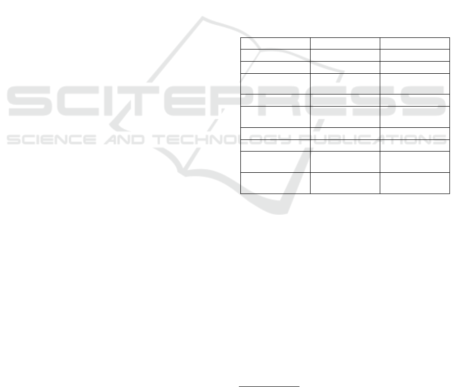
Table 1: Input/Output data of the decoder operations.
Operation Input Output
Remove CP 30720 samples 2048 samples
2
DFT 2048 samples
2
2048 samples
2
Sub-carrier
demapping
2048 samples
2
1200 samples
2
IDFT 1200 samples
2
1200 samples
2
Demodulation 1200 resource
elements
3
7200 soft bits
3
Descrambling 7200 soft bits
3
7200 soft bits
3
LDPC decoder 1944 soft bits
3
1620 hard bits
3
Code Block
Concatenation
1620 hard bits
3
66416 hard
bits
3
Remove CRC 66416 hard
bits
3
66392 hard
bits
3
In this case study we use two target platforms.
One is Embb (Embb, 2017), a generic baseband
architecture dedicated to signal-processing appli-
cations. Embb is composed of a Digital Signal
Processing (DSP) part and a general purpose con-
trol part. The DSP part is composed of a set of
Digital Signal Processing Units interconnected
by a crossbar. Each DSP unit is equipped with a
Processing Sub-System (PSS) as computational unit,
a Direct Memory Access controller (DMA) and a
local memory called the Memory Sub-System, MSS.
These DSPUs can be seen as programmable IPs that
are more flexible than traditional fully hard-wired
accelerators. The general purpose control part is
composed of a RAM memory and of a CPU that
2
Per OFDM symbol; samples are stored on 32 bits.
3
Per frame; resource elements and soft bits are stored on
8 bits.
A Model Compilation Approach for Optimized Implementations of Signal-processing Systems
31
Descrambling
64QAM
Demodulation
Sub-carrier
demapping
N-point
DFT
LDPC
decoder
M-point
IDFT
Remove
Cyclic
Prefix (CP)
Code
Block
Concatenation
Check and
remove
CRC
RX transport
block
41 code blocks
14 OFDM symbols
from
RF/ADC
Figure 3: The block diagram of the 5G decoder designed in this case study.
QAMDemod
X_QAMDemod
F_QAMDemod
getReqArg (size)
SubCarrierDemap_ChOut(numBitsPerSymbolOUT)
SubCarrierDemap_ChIn(numBitsPerSymbolIN)
for(i=0;i<num_symbols;i = i+1)
inside loop
exit loop
numBitsPerSymbolIN
(a) (b)
Figure 4: The SysML Composite (a) and Activity (b) dia-
grams for operation 64QAM Demodulation.
configures and controls the processing operations
performed by the DSPUs and the data transfers.
The architecture of the second target platform, a
hardware IP-based platform is composed of a
programmable and of a configurable subsystem. The
programmable subsystem executes control func-
tions as well as signal-processing operations whose
performance are not time critical. It is composed
of a CPU and a RAM memory. The configurable
subsystem accelerates performance-critical opera-
tions onto dedicated hardware IP blocks that can
be selected by Xilinx SDx (Xilinx, 2017) from
the target program produced by our compiler. An
IP block includes a processing core, a local mem-
ory and a DMA engine, similarly to a DSPU in Embb.
Thanks to the similarities in the structure of the two
target platforms, we captured their architecture in the
UML Deployment diagram of TTool/DIPLODOCUS
of Fig. 5.
<<CPU>>
Main CPU
<<MEMORY>>
Main Memory
<<BRIDGE>>
<<BUS>>
Main Bus
Digital Signal Processing part
General-Purpose Control Part
<<BUS>>
Crossbar
<<HWA>>
IP[1..*]
Main
Bridge
Figure 5: The UML Deployment Diagram of a generic in-
stance of Embb and of the hardware IP-based platform.
In Fig. 5, the left-hand part describes the subsys-
tem where the processing of data is accelerated. Here,
a PE (Processing Element) block models the architec-
ture of a DSPU in Embb or a hardware IP block. The
TTool/DIPLODOCUS model of a PE’s internal archi-
tecture is depicted in Fig. 6. The right-hand side of
Fig. 5 captures the control part of our two target plat-
forms: a CPU and a memory units interconnected by
a bus unit.
To compile executable code, we instantiated, in
TTool/DIPLODOCUS, a PSM model such as the one
in Fig. 5 that contains two Processing Elements for
Embb and one Processing Element for the IP-based
platform. The mapping information corresponding to
these PSMs is illustrated in Fig. 7.
<<BUS-RR>>
IP_Internal_Interconnect
<<BRIDGE>>
IPBridge
<<MEMORY>>
IP_Local_Memory
<<DMA>>
IP_DMA
<<CPURR>>
Processing_Core
to global interconnect
Figure 6: The UML Deployment Diagram for the generic
architecture of a PE in Fig. 5.
5.1 The Model Compilation
The optimization techniques used by our model com-
piler reduce the memory footprint by sharing the
physical buffers among operations that are mapped to
a given execution unit. To understand this optimiza-
tion, Fig. 7 shows one of the intermediate representa-
tions used by our compiler: the SDF graph of the 5G
decoder in Fig. 3. Nodes in Fig. 7 represent the op-
erations in Fig. 3 and edges represent logical memory
buffers. The size of each logical buffer is given by the
production and consumption rates (tokens) of input
and output edges. For instance, for node B (operation
DFT), the size of its input logical buffer B
in
is 8192
bytes and the size of its output logical buffer B
out
is
8192 bytes. In the case of Embb, based on the map-
ping information indicated below nodes in Fig. 7, we
identify 3 sets of logical buffers, B
0
, B
1
, B
2
, that
are associated to operations mapped onto the same ex-
ecution unit. For the Main CPU the logical buffers are
B
0
= {A
out
, F
in
, F
out
, H
in
, H
out
, I
in
}. For unit
FEP DSPU, the buffers are B
1
= {B
in
, B
out
, C
in
,
C
out
, D
in
, D
out
, E
in
, E
out
}. For unit LDPC DSPU
the buffers are B
2
= {G
in
, G
out
}.
The target C program produced by the back-end is
based on a library of 371 implementation-specific
functions.
For the IP-based platform, based on Fig. 7, we iden-
tify 2 sets of logical buffers, B
3
, B
4
, that are as-
sociated to operations mapped onto the same execu-
tion unit. For the Main CPU the logical buffers are
B
3
= {A
out
, B
in
, B
out
, C
in
, C
out
, D
in
, D
out
,
E
in
, E
out
, F
in
, F
out
, H
in
, H
out
, I
in
}. For the
MODELSWARD 2018 - 6th International Conference on Model-Driven Engineering and Software Development
32

A
Remove CP
B
C
D
E
F
G
H
I
Main CPU FEP DSPU FEP DSPU FEP DSPU FEP DSPU Main CPU LDPC DSPU Main CPU Main CPU
DFT Demapping IDFT Demodulation Descrambling LDPC Code Block Remove CRC
Main CPU Main CPU Main CPU Main CPU Main CPU IP core Main CPU Main CPUMain CPU
IP-based platform mappingEmbb mapping
8192
8192
8192
8192
4800
4800
4800
4800
7200
7200
7200
1944
203
203
8302
8302
Figure 7: The SDF graph of the 5G decoder in Fig. 3 with mapping information. Tokens are expressed in bytes.
IP core, the logical buffers are B
4
= {G
in
, G
out
}.
The back-end composes a target program by linking
a library of 33 implementation-specific functions for
each operation in Fig. 3.
In terms of memory footprint, each set of logical
buffers is transformed by the compiler’s middle-end
into a shared physical buffer, whose size is equal to
the set’s largest logical buffer. This corresponds to
H
out
for B
0
, to B
out
for B
1
, to G
in
for B
2
, to H
out
for
B
3
and to G
in
for B
4
.
5.2 The Target Program Translation
In the case of Embb, the target C program is trans-
lated into an executable with GNU/gcc v.5.4.0 cross-
compiled onto Ubuntu v.16.04.4. This executable (a
pure software implementation of the input models)
runs on the main CPU in Fig. 5 as a user-space ap-
plication for Linux v.4.4.0-xilinx.
In the case of the IP-based platform, we translate
the target C program with Xilinx SDx (Xilinx, 2017)
into a mixed hardware-software implementation. The
output of the Xilinx SDx translation process are a
Linux image and an .elf file for the software part of
the implementation, to be executed by the CPU of
the programmable subsystem. The executable for the
hardware part of the implementation is a FPGA bit-
stream. The latter is loaded into the target FPGA’s
configurable fabric by a Linux image that runs onto
the FPGA’s control processor (not represented in our
models).
5.3 Evaluation
In the case of Embb, the middle-end allocates 8192
bytes for B
1
to the local memories of the FEP DSPU,
which is equal to the size of B
in
. It allocates 1944
bytes for B
2
to the local memory of the LDPC DSPU,
which is equal to the size of G
in
, and 8302 bytes
for B
0
to the Main CPU memory, which is equal
to the size of H
out
. Assigning separate I/O FIFO
buffers to each of the 5G decoder operations would
have allocated 50976 bytes to the FEP local memory
(the size of all logical buffers in B
1
), 2147 bytes
to the LDPC processor’s local memory (the size of
all logical buffers in B
2
) and 39399 bytes to the
main CPU memory (the size of B
0
). Compilation
reduces the memory footprint of 83.88%, 9.46% and
78.93% for each of these three units, respectively.
Overall, it reduces by 80.07% the memory used
by the final executable code, with respect to pure
translation-based approaches.
For the IP-based platform, the middle-end allocates
8302 bytes for B
3
to the main CPU memory (the
programmable system), which is the size of H
out
,
and 1944 bytes for B
4
to the hardware IP-core
memory (configurable system), which is the size of
G
in
. A pure translation-based approach that allocates
separate I/O FIFO buffers to each operation would
have reserved 90375 bytes (the size of B
3
) and 2147
bytes (the size of B
4
) to the main CPU and the
hardware IP-core memories, respectively. Our com-
pilation achieves a memory footprint reduction equal
to 90.81% and 9.46%, respectively, for these two
units. Overall, this reduces by 88.93% the memory
used in the mixed hardware-software implementation.
The middle-end of our compiler optimizes an appli-
cation’s memory footprint by accounting for the map-
ping information of SDF actors onto a platform’s exe-
cution units. This scheduling update does not impact
the overall timing properties of the final executable.
Specifically to this 5G decoder, its real-time proper-
ties are limited by two factors. First, by the lack of
parallelism between operations that is inherent to the
application in Fig. 3. Secondly, by the absence in the
target platforms of multiple units capable to process
different OFDM symbols in parallel. Because of the
limited size of the FPGAs onto which we prototyped
our platforms, it was only possible to instantiate one
Front-End Processor unit and one LDPC processor in
Embb as well as one hardware IP-block in the sec-
ond platform. For instance, in Embb, the availability
of only one FEP unit does not allow to pipeline the
execution of operations DFT, Demapping, IDFT and
Demodulation for consecutive OFDM symbols.
6 CONCLUSION
This paper proposes a compilation approach of
system-level models for SoC implementations of
signal-processing applications. With respect to
the translation-based approaches discussed in Sec-
A Model Compilation Approach for Optimized Implementations of Signal-processing Systems
33

tion 2, we showed that optimizing (compiling) the
non-functional properties (i.e., memory footprint) of
model-based specifications can result in significant
performance improvement without impacts on the se-
mantics of the system begin modeled. In the domain
of MDE for SoCs, we believe that this further reduces
the gap between traditional programming approaches
based on C/C++ and model-based programming tech-
niques.
In future work, we will extend our case study with the
complete design of an encoder chain and we will inte-
grate other optimizations (e.g., power consumption).
ACKNOWLEDGEMENTS
The authors would like to thank Karol Desnos from
INSA Rennes for his precious advice on data-flow
MoCs and the memory reduction techniques (Desnos
et al., 2014; Desnos et al., 2016).
REFERENCES
Alf (2017). Action language for foundational uml (alf).
http://www.omg.org/spec/ALF/.
Apvrille, L. (2008). Ttool for diplodocus: An environ-
ment for design space exploration. In NOTERE, pages
28:1–28:4.
Apvrille, L., Muhammad, W., Ameur-Boulifa, R., Coudert,
S., and Pacalet, R. (2006). A uml-based environment
for system design space exploration. In ICECS, pages
1272–1275.
Bazydlo, G., Adamski, M., and Stefanowicz, L. (2014).
Translation uml diagrams into verilog. In HSI, pages
267–271.
Ciccozzi, F., Cicchetti, A., and Sjodin, M. (2012). Full code
generation from uml models for complex embedded
systems. In STEW.
DaRTteam (2009). Graphical array specification for
parallel and distributed computing (gaspard2).
http://www.gaspard2.org/.
Desnos, K., Pelcat, M., Nezan, J., and Aridhi, S. (2014).
Memory analysis and optimized allocation of dataflow
applications on shared-memory mpsocs. Journal of
VLSI Signal Processing Systems for Signal, Image,
and Video Technology, pages 1–19.
Desnos, K., Pelcat, M., Nezan, J., and Aridhi, S. (2016). On
memory reuse between inputs and outputs of dataflow
actors. ACM Transactions on Embedded Computing
Systems, pages 30:1–30:25.
Embb (2017). http://embb.telecom-paristech.fr/.
Enrici, A., Apvrille, L., and Pacalet, R. (2017). A model-
driven engineering methodology to design parallel
and distributed embedded systems. ACM TODAES,
22(2):34:1–34:25.
Fabri, J. (1979). Automatic storage optimization. Courant
Institute of Mathematical Sciences, New York Univer-
sity.
Feiler, P. and Gluch, D. (2012). Model-Based Engineering
with AADL: An Introduction to the SAE Architecture
Analysis & Design Language. Addison-Wesley Pro-
fessional.
Floch, A., Yuki, T., Guy, C., Derrien, S., Combemale, B.,
Rajopadhye, S., and France, R. B. (2011). Model-
driven engineering and optimizing compilers: A
bridge too far? In MODELS, pages 608–622.
fUML (2016). http://www.omg.org/spec/FUML/1.2.1/.
Gamatie, A., Beux, S. L., Piel, E., Etien, A., Atitallah, R. B.,
Marquet, P., and Dekeyser, J. L. (2008). A model
driven design framework for high performance em-
bedded systems. http://hal.inria.fr/inria-00311115/en.
Gerstlauer, A. and Gajski, D. D. (2002). System-level ab-
straction semantics. In 15th International Symposium
on System Synthesis, pages 231–236.
Gerstlauer, A., Haubelt, C., Pimentel, A. D., Stefanov, T. P.,
Gajski, D. D., and Teich, J. (2009). Electronic system-
level synthesis methodologies. IEEE Transactions
on Computer-Aided Design of Integrated Circuits and
Systems, 28(10):1517–1530.
GNURadio (2017). Gnu radio. http://gnuradio.org/.
Gomaa, H. (2016). Overview of UML, SysML, and MARTE,
pages 12–31. Cambridge University Press.
Labview (2017). Labview communications system design.
http://www.ni.com/labview-communications/.
Lee, E. A. and Parks, T. M. (1995). Dataflow procees net-
work. Proceedings of the IEEE, 83(5):1235–1245.
Mathworks, T. (2017). https://www.mathworks.com/soluti
ons/model-based-design.html.
Mellor, S. J. and Balcer, L. (2002). Executable UML: A
Foundation for Model-Driven Architecture. Addison
Wesley.
Mellor, S. J. and Balcer, M. J. (2003). Executable
and translatable uml. http://www.omg.org/news/meet
ings/workshops/
UML 2003 Manual/Tutorial4-Balcer.
Mischkalla, F., He, D., and Mueller, W. (2010). Closing
the gap between uml-based modeling, simulation and
synthesis of combined hw/sw designs. In DATE, pages
1201–1206.
Moreira, T. G., Wehrmeister, M. A., Pereira, C. E., Petin,
G. F., and Levrat, E. (2010). Automatic code gener-
ation for embedded systems: From uml specifications
to vhdl code. In International Conference on Indus-
trial Informatics, pages 1085–1090.
Nicolas, A., Penil, P., Posadas, H., and Villar, E.
(2014). Automatic synthesis over multiple apis from
uml/marte models for easy platform mapping and
reuse. In Euromicro DSD, pages 443–450.
OMG (2017). Uml profile for marte: Model-
ing and analysis of real-time embedded systems.
http://www.omg.org/omgmarte/.
Schmidt, D. C. (2006). Model-driven engineering. Com-
puter, 39(2):25–31.
MODELSWARD 2018 - 6th International Conference on Model-Driven Engineering and Software Development
34

Tan, W. H., Thiagarajan, P. S., Wong, W. F., Zhu, Y., and
Pilakkat, S. K. (2004). Synthesizable systemc code
from uml models.
Torczon, L. and Cooper, K. (2007). Engineering a Com-
piler. Morgan Kaufmann Publishers Inc., San Fran-
cisco, CA, USA, 2nd edition.
Vanderperren, Y., Mueller, W., He, D., Mischkalla, F., and
Dehaene, W. (2012). Extending uml for electronic
systems design: A code generation perspective. In
Design Technology for Heterogeneous Embedded Sys-
tems, pages 13–39.
Verizon (2015). 5g specifications. http://www.5gtf.org/.
Xi, C., JianHua, L., Zucheng, Z., and Yaohui, S. (2005).
Modeling systemc design in uml and automatic code
generation. In ASP-DAC, pages 932–935.
Xilinx (2017). Sdx development environment. https://www.
xilinx.com/products/design-tools/
all-programmable-abstractions.html.
A Model Compilation Approach for Optimized Implementations of Signal-processing Systems
35
