
Embedded Navigation and Classification System for Assisting Visually
Impaired People
Antonio Miguel Batista Dourado
1,2
and Emerson Carlos Ped rino
1
1
Department of Computing, Federal University of S˜ao Carlos, Rod. Washington Lu´ıs - Km 235, S˜ao Carlos-SP, Brazil
2
Federal Institute of S˜ao Paulo - Boituva Campus, Av. Z´elia de Lima Rosa - 100, Boituva-SP, Brazil
K
eywords:
Visually Impaired People, Electronic Travel Aids, Computer Vision System, Navigation System, Object
Recognition, Object Classification.
Abstract:
Loss of vision has a large detrimental impact on a person’s mobility. Every day, visually impaired people
(VIPs) face various challenges just to get around in the most diverse environments. Technological solutions,
called Electronic Travel Aids, help a VIP with these challenges, giving greater confidence in the task of getting
around in unfamiliar surroundings. Thus, this article presents an embedded navigation and classification
system for helping VIPs indoors. Using st ereo vision, the system is able to detect obstacles and choose
safe ways for the VIP to walk around without colliding. A convolutional neural network using a graphics
processing unit (GPU) classifies the obstacles. Acoustic feedback is transmitted to the VIP. The article also
features a wearable prototype, to which the system hardware is docked for use. Using the system, the prototype
could detect and classify obstacles in real time defining free paths, all with battery autonomy of about 6 hours.
1 INTRODUCTION
Electronic Travel Aids (ETAs) have gained promi-
nence in the last decade in the area of visual impair-
ment. The World Health Organiza tion (WHO, 2014)
reported that there are at least 285 million visually
impaired people (VIPs), considering partial and total
loss of vision, thus making ETAs important tools that
can be built into the day-to-day life of a visually disa-
bled person.
In terms of hardware, ETAs can be developed in
different ways depending mainly on the type of in-
put sensors and how information is transmitted to the
visually impaired person (VIP). Input sensors com-
monly found in the litera ture are GPS cameras, IMUs,
RFID readers, infrared lasers and othe rs (Fajarnes
et al., 2010 ; Katz et al., 2012; M ehta et al., 2011;
Tapu et al., 2016). Each input sensor can be used al-
one or in conjunctio n with others to provide safety
informa tion to the user via acoustic audio feedback
(Schauerte et al., 2012), where sounds represent the
informa tion, or the user receives some other physical
stimulus, such as vibrations (Bourbakis, 2008).
A device to help safe navigation for a VIP must,
however, allow the user good mobility, in terms of the
weight and size of the device (Pissaloux, 2002) . This
premise makes it unfeasible that an ETA device h as a
PC o r a notebook a s the processor, since the former
is not mobile, (although some PC based systems use
cloud processing), and the latter, while offering a cer-
tain degree of mobility, still tend s to be quite heavy.
One possible solution for local processing is to make
an ETA with an embedded system, albeit with more
limited p rocessing power.
The segmentation of free paths and classification
of obstacles in embedded platforms have been parti-
ally explored in some studies, as seen in Section 2,
however there is no approach tha t considers presen-
ting multiple paths to the user, nor any work using re-
cent object classification techniques using deep neural
networks with graphics processing units (GPUs).
This paper presents an embedded ETA that help s
the VIP with navigation, throu gh th e recognition and
classification of indoor obstacles, providing acoustic
feedback. The system was built in an NVIDIA Jetson
Tegra X1 module (NVIDI A , 2 017) that has a CUDA
256-core video card for parallel processing and offers
high perf ormance with low power consumption. The
images are ca ptured through the sensors of an RGB-D
camera and processed. The use of a RGB-D camera
imposes an indoor environment lim itation, knowing
that external env ironmen ts have a high incidence of
infrared light which may interfere with the camera’s
image capture. For the classification of obstacles, the
516
Dourado, A. and Pedrino, E.
Embedded Navigation and Classification System for Assisting Visually Impaired People.
In Proceedings of the 13th International Joint Conference on Computer Vision, Imaging and Computer Graphics Theory and Applications (VISIGRAPP 2018) - Volume 5: VISAPP, pages
516-523
ISBN: 978-989-758-290-5
Copyright © 2018 by SCITEPRESS – Science and Technology Publications, Lda. All rights reserved

ETA will use Convolutional Neural Networks (CNN),
a ca tego ry of Deep Neural Network that has produce d
great results since its first app e arance in 2012 in the
ILSVRC competition ( Krizhevsky e t al., 2012).
The article is divided as follows: Section 2 pre-
sents studies related to this one that have been repor-
ted in the literature. In Section 3, the proposed sy-
stem is described along with the architectur e in which
it was developed. Section 4 describes the developed
prototy pe and the experiments performed using the
system and the results are shown in section 5. Fi-
nally, in Section 6, the conclusions a nd future work
are given.
2 RELATED WORK
The literature about recognition and classification na-
vigational systems for VIPs describes several diffe-
rent approach es to address the issues of safe paths and
the classification of obstacles.
Mocanu et al. (2015) used the classic fea tures ex-
traction technique to classify obstacles with an adap-
tation of the Histogram of Oriented Gr adients (HOG)
and they represented images globally using techni-
ques like the Vector of Locally Aggregated Descrip-
tors (VLAD) and the Bag of Visual Word (BoVW)
framework. The images are ranked in conjunction
with Support Vector Machines (SVM). The imple-
mentation is done on a smartphone and the proces-
sing reache s a maximum of 5 fps. It is important to
emphasize that, although 5 fps is an acceptable per-
formance for VIPs, the authors did not suggest safe
paths and they do not make it clear how the VIP is
informe d ab out the obstacles.
The idea pr oposed by Deb et al. (2013) aims pre-
dominantly at the safe navigation of the VIP by esti-
mating the safe direction in which they can walk. In
the projec t, authors use a simple camera for image
acquisition and apply tec hniques such as edge de-
tection and pyramidal segmentation to the n define a
safe zone using Template Matching and transmit via
musical tones whether th e safe path is to th e right or
left. The area analyzed is center-bottom of the image.
So th e VIP is not alerted to possible (and unclassi-
fied) obstacles above the ground and the proposed sy-
stem disregards much of the left and right sides of the
image which, in some cases, could have alternative
routes. Fina lly, the authors also state that, in the c ase
of two safe paths, the system will always choose the
left side and not even present the alternative to the
VIP periodically.
The use of embe dded platforms for VIPs was ex-
plored by Bangar et al. (2013), using recognition of
objects and their color s. In their research, the authors
extract the images from a coupled video sensor in a
pair of glasses and apply procedures like backgrou nd
extraction, edge detectio n and pixel clustering to de-
fine an object and also its color, using a standard color
scheme. The system then passes the result of proces-
sing to the VIP via stereo sound. Colo r detection after
object detection is an important factor for classifica-
tion, but the authors do not classify the object c om-
pletely and, although mentioning stereo sound, do not
mention in their work if the au dio is used in a way
that transmits the direction of the object. The work
also d oes not aim for or try to explain the segmenta-
tion of fre e paths.
Poggi and Matto c cia (2016) also use embedded
technology for the implementatio n of an intelligent
system f or VIPs. In their work, the author s use an
Odroid U3 device in communication with a smartp-
hone, head phones, tactile feedback glove, and dee p
camera goggles as an embedded platform and the sy-
stem classifies obstacles using convolutional neural
networks, but without the acceleration of a Graphics
Processing Unit (GPU). There is a navigation stage
but only via the GPS of the smartphone and the sy-
stem proposed by the authors does not define safe
paths, only dealing with the classification of obsta-
cles and their positioning and informing the user of
the GPS directions.
3 PROPOSED SYSTEM
The system developed here has been divided into five
main stages: image acquisition, preprocessing, free
path segmentation, obstacle detectio n an d acoustic
feedback as shown in Figure 1. Image acquisition
is a sim ple an d obvious pr ocess in which two 640 x
480 images are rec eived from the RGB-D sensor, one
depth an d one color.
Preprocessing only happens for the depth image.
The original depth image captured by the RGB-D sen-
sor contains several faults with indefinite depths, ge-
nerating chromatic irregularities in the d e pth image.
The prepr ocessing corrects such flaws using mathe-
matical morphology. The image is dilated and then
reduced again to the same 21 by 21 element square
structure. Then it’s submitted to a free path segmenta-
tion, obstacle detection and acoustic feedback stages,
which are presented in the subsections below.
3.1 Free Path Segmentation
To determine one or more safe paths for the user,
the RGB-D camera depth image has b een divided
Embedded Navigation and Classification System for Assisting Visually Impaired People
517
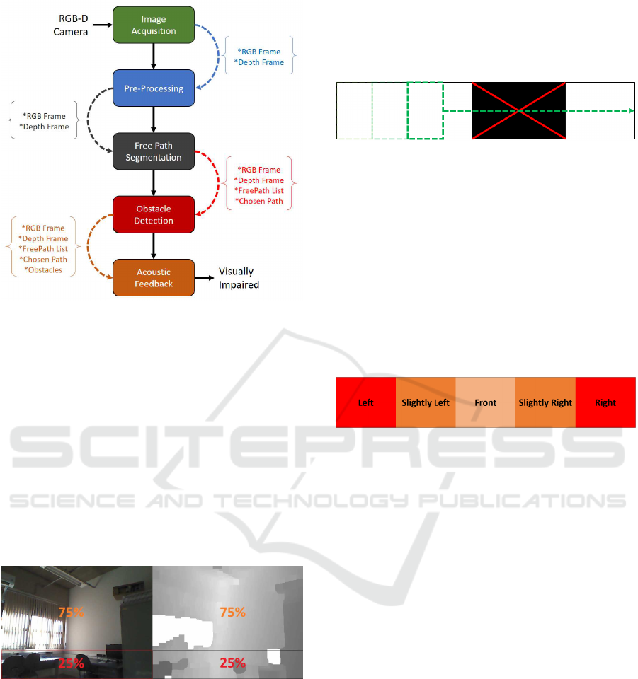
Figure 1: System Overview.
into four horizontal parts and, in this stage only, the
bottom of the image has been taken, i.e . the bottom
25% of the image is proc essed. Th e reason for this is
that the VIPs will carry the camera in their belly re-
gion during the use of th e prototype and, considering
the field of vision of the camera, the lowest quarter of
the image contains more elements that limit the na-
vigation of the VIP. The top 75% of the image, ho-
wever, is not discarded but processed for obstacle de-
tection after the indicated safe path has been chosen.
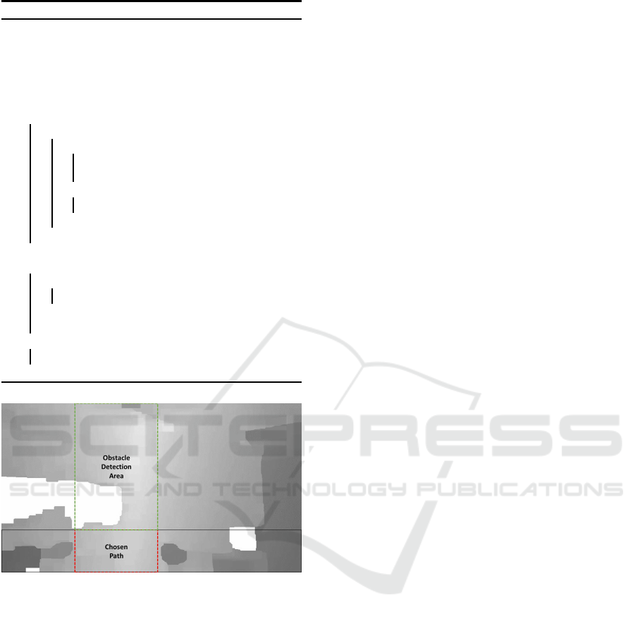
Figure 2 shows the selected low est area o f the color
and depth images but, as mentioned, only the depth
image is used f or path segmentation.
Figure 2: Splitting process. RGB Image (left) and Depth
Image (right).
When the lowest 25% of the image is separated,
the Template Matching technique (Brunelli, 2009)
is applied to define which areas of the ima ge are
safe for navigation. Before the template matching is
done, a simple thresholding operation is done on the
bottom slice of the image to separate the possible free
paths from those with obstacles. To define the free
paths, a template, 50 pixels wide by the he ight of the
bottom slice, performs the template matching opera-
tion throughout the length of the slice, as shown in
Figure 3 . Regions next to free paths are joined to-
gether and consider e d as one region and its centroids
added to a list of coordinates that, in the end, is used
by the system to give the direction to the VIP.
Figure 3: Sliding template (Green) for free path segmenta-
tion. Dark areas indicate obstacles.
If more than one path is separated, the options will
be sent via acoustic feedback and then the path closest
to the center of the image will be chosen. The sy-
stem considers five possible directions of o rientation
for VIPs in the free path segmentation: right, slightly
right, f ront, slightly lef t and left (Figure 4). Each re-
gion corresponds to 20% of the imag e so ’slightly le ft’
and ’slightly right’ mean the user should turn slightly
in the specified direction, while the right and left di-
rections de fine the user should turn between 30
◦
and
45
◦
in that direction.
Figure 4: Directions defined by image regions.
Algorithm 1 contains th e pseudocode for the free
path segmentation stage. The code determines one o r
more free paths and chooses the closest to the center,
if any. A list with the X coordinates of the ce nters
of the free paths and also the path chosen are those
resulting from the code.
With on e free path determined, the system may
then look at verifying the existence of an obstacle in
that direction.
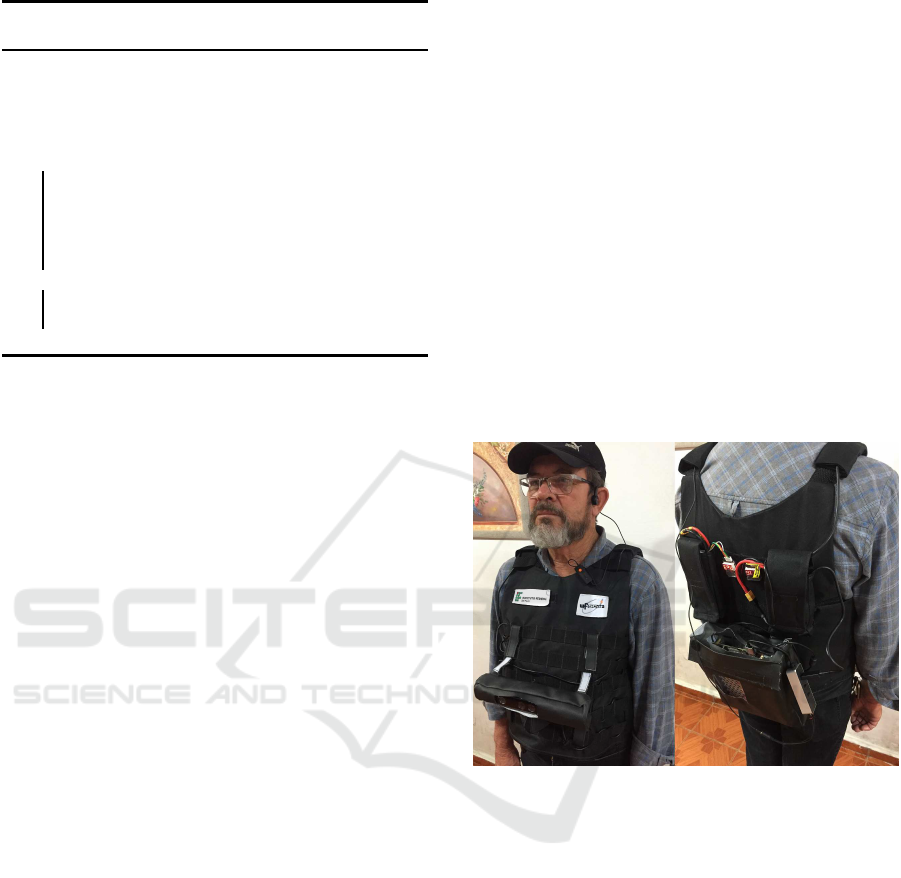
3.2 Obstacle Detection and
Classification
Although free path segmentation occurs in the bottom
25% of the image, the detection and classification of
obstacles occurs in the upper 75% of the imag e as
shown in Figure 5. However, this stage only occ urs
if and when a free path is ch osen, since obstacle
checking occurs only in the direction of such a cho-
sen path. The a reas of the image relative to any not-
selected paths are ignored and not proc essed in search
of obstacles. This search for obstacles in the upper
part of the image is because several objects, such as
an open drawer or a cupb oard door, could block the
space above the free path and prevent the user from
walking forward.
VISAPP 2018 - International Conference on Computer Vision Theory and Applications
518
Algorithm 1: Fr ee Path Segmentation Algorithm
Data: DepthFrame
Result: List of Free Paths, Chosen Path
1 bottomSlice = imageYSplit(DepthFrame,4)[4]
2 bottomSlice = threshold(bottomSlice,
distanceThreshold)
3 template = Rectangle(50,bottomSlice.height)
4 while Sliding template through bottomSlice do
5 if template matches then
6 if adjacent region then
7 updateLastFreePath(freePaths,
XCenterCoordinate)
8 else
9 freePaths = XCenterCoordinate
10 end
11 end
12 end
13 i f freePaths >0 then
14 if freePaths >1 then
15 sendAcousticFeedback(freePaths)
16 end
17 chosenPath = pickCentralPath(freePaths)
18 el se
19 sendAcousticFeedback(”No path found.”)
20 end
Figure 5: Obstacle detection area (green).
The upper slice of the image, as well as the lo-
wer one, is also subjected to a thresholding operation
(with the same value as the lower slice) to delimit clo-
ser obstacles, and then a new pixel operation defines,
if any, the obstacle closest to the defined area. Any
obstacle detected is defined by a Canny edge detector,
its contours drawn and a bounding box is created for
that obstacle. For best results, the bounding box area
is increa sed by 25 % to avoid cropping the borders of
the obstacle.
Obstacle classification u ses a convolutional neural
network, using the Caffe framework (Jia et al., 201 4).
A 22-layer GoogL e N et (developed by Google) model
(Szegedy et al., 2015) was trained to classify twenty
classes of objects: anim al, cabinet, vacuum cleaner,
bag, chair, bed, basket, stove, refrigerator, window,
table, backpack, person, sink, d oor, sofa, monitor and
toilet. About 60,000 images were used for the trai-
ning, reaching 82% classification accuracy for Top-1
prediction and 95% for Top-5 prediction (the correct
class is one of the top five ranked c la sses) after 35
epochs. Although many of the trained obje cts are not
usually detected in the upper 75% of the im a ge, espe-
cially in the experiments of this study, the model will
also be used for a future study mentioned in Section 6.
However, the model is able to classify hanging back-
packs and table corners, for example. In cases where
the obstacle can not be classified, the system will emit
a warn ing sound about the obstacle but not identifying
it.
When an obstacle has been detected and its region
determined, the defined bounding box is used to ex-
tract the sub-image from the RGB image containing
the obstacle. This sub-image is sent to the classifier
which returns a list of the five most likely classes of
the ima ge and their accuracy percentages. The co n-
fidence of the classification of the o bstacle is divided
into three bands according to the percentage of accu-
racy:
Co n f (img) =
100%, if Predict(img)
1
≥ 90%
50%, if Predict(img)
1
≥ 60%
and Predict(img)
2
≤ 30%
0%, other wise
The confidence defined by Conf(img) directly informs
the feedback that the VIP will receive from the sy -
stem, as shown in Section 3.3, , an d ranges from total
certainty that the obstacle is of a given class to unable
to identify the obstacle. With the information provi-
ded, the function Predic(img)
x
is called to classify the
image (img) and its index (x) is the position o f the re-
sult in the list, with 1 be ing the most accurate, 2 the
second most accurate and so on. Algorithm 2 shows
the pseudocode for the detection and classification of
an obstacle.
3.3 Acoustic Feedback
Acoustic feedback im plies in processed system in-
formation of intere st to the user passed to them via
sound. The system developed here performs two ty-
pes of acoustic feedback: via voice, in which feed-
back con sists of words informing the user about a free
path or an obstacle; and v ia tones, in case a detected
obstacle cannot be correctly classified or only classi-
fied with low accuracy. Thus the types of feedback
that the system can provide are:
• Directions (voice), informing the direction in
which the defined free path is. In this case the
phrases were defined as: ”left”, ”slightly left”,
”front”, ”slightly r ight” and ”right”;
Embedded Navigation and Classification System for Assisting Visually Impaired People
519
Algorithm 2: Obstacle Detection and Classifi ca-
tion Algorithm
Data: DepthFrame, RGBFrame, ChosenPath
Result: Acoustic Feedback
1 upperSlice = imageXSplit(DepthFrame, ChosenPath)
2 obstacles = threshold(upperSlice, distanceThreshold)
3 obstacle = getNearestObstacle(obstacles)
4 if nearestObstacle is not null then
5 obstacleImg = cropImage(RGBFrame, obstacle)
6 obstacleClass = classify(obstacleImg)
7 obsInfo = {obstacle, obstacleClass}
8 sendAcousticFeedback(chosenPath, obsInfo,
RGBFrame, DepthFrame)
9 else
10 sendAcousticFeedback(chosenPath, NULL,
RGBFrame, DepthFrame)
11 end
• No direction ( voice), when the system is not able
to find a safe path, the sentence informed the user
is ”No path”;
• Obsta cle class (voice), identifying the obstacle
after its classification only by its class and posi-
tion via 3D audio. Two types of messages can
be sent to the user. If the prediction reliability is
100%, the system will simply send the obstacle
class as f e edback. For 50% reliability, the system
will report that the obstacle appears to be of the
informe d class, by means of the sentence ”It ap-
pears to be <class>”;
• Unclassified obstacle (tone ), if the obstacle can
not be classified, will be issued a tone towards the
obstacle, rathe r than say the class of the obstacle.
In order to preserve the conta ct of VIPs with the
sounds of th e environment around them, this de sig n
uses a non-invasive bone-conducting stereo headset
that allows both system feedback and ambient sounds
to be hea rd simu ltaneously. The system also converts
the so unds of obstacle positions into 3D positioning,
indicating by sound if an obstacle is to the right, left or
center of the path. The text-to-speech synthesis of the
above phra ses was done with the eSpeak library (ES-
peak, 2007) and reprod uced by the OpenAL library
(Hiebert et al., 2017), which was also used reprodu-
cing the ton e of an unclassified obstacle.
4 EXPERIMENT
The propo sed system aims at improving mobility of
VIPs and their relative comfort without detriment to
the system performanc e. So, before experimenting
with the system, a functional, wearable prototype for
navigating had to be developed.
4.1 Wearable Prototype
The prototype hardware seeks to minimize the impact
on both the movement and also the hearing of VIPs,
avoiding their total sensory immersion in the sy-
stem. The prototyp e consists of: a Kinect for XBOX
360 RGB-D camera, an NVIDIA Jetson TX1 board,
Aftershokz Sportz M2 bone conduction headphones
with built-in microphone, a LiPo 3S 2.200MAh bat-
tery to p ower the RGB-D camera and a 2.2200MAh
4S LiPo battery as the Jetson TX1 power source.
The Kinect camera is surrounde d by a fabric co-
ver. This cover is used to attach the camera to a spe-
cial dress for VIPs tailored from a tactical (airsoft)
vest. The vest is used not only to attach the camera
to the front, but also to attach to three other compart-
ments on the back that carry both batteries and the
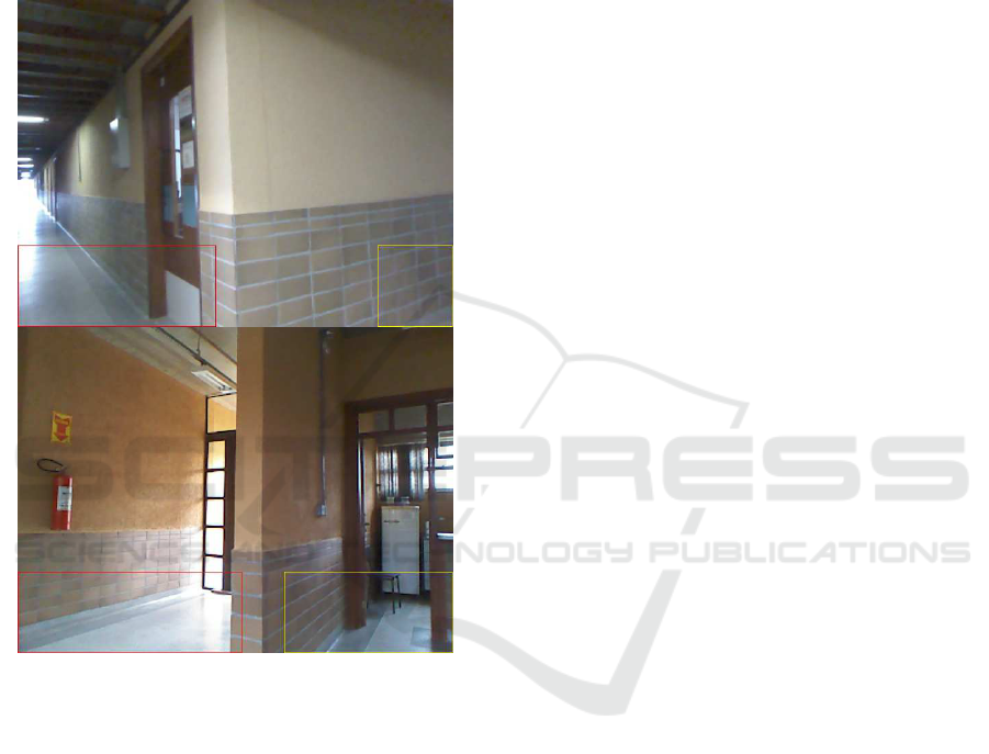
Jetson TX1 card. Figure 6 shows a person wearing
the prototype vest with the attach ed equipment.
Figure 6: Prototype equipment for developed system. Front
(left) and back (right).
4.2 Practical Experiment
The prototype was tested in the corridors of the de-
partment to w hich the project is linked. Although
a pa rtnership with a non-g overnmental organization
(NGO) for VIPs already exists, th e first testing was
done with a fully-sighted p e rson and a future version
of the system will be tested b y the VIP members of
the NGO.
The experiment consisted of following several
paths through the corridors, shown in Figure 7, where
the green dot indicates the beginning of the route, the
red do ts indicate the e nd and each line linking them
indicates a path. This sought to check if the system
would prevent collisions between the participant and
any object, wall or person, in addition to in dicating
the free paths including the most central. The sy-
stem was configured and tested for detectio n o f free
VISAPP 2018 - International Conference on Computer Vision Theory and Applications
520

paths fro m three maximum distances: 80cm, 120cm
and 160cm. All the test r outes were followed for each
of these three configurations.
None of the surroundings in the de partment were
adapted for the experiments nor was the movement of
people restricted at any time the routes were being
followed, in order to encourage chance en counters
with people and the respo nse of the system to such
an event.
During the experiment, the authors also looked at
the questions of the speed and time of the fe e dback
in relation to the user’s reaction, i.e. if the time spent
sending the feedback is adequate so that the user can ,
for example, avoid bump ing into a wall. The classi-
fication of obstacles was also checked during the ex-
periment, including its impact on the perfo rmance of
the system.
5 RESULTS
For all the r outes followed, the system was able to
help with safe navigation, since there were no collisi-
ons with walls, people or obstacles in general.
Each maximum d istance produced different sy-
stem behavior. The 80cm distance could inform the
user in a timely manner about changing a path or ob-
stacle but the authors observed that the user reaction
time and the speed of their steps can be a problem if
they walk fast and have slower reactions. A maximu m
distance o f 150cm was en ough to detect obstacles and
we believe that a slow reaction from user f or system
feedback is not a problem for such distance. However,
there was an issue f ound for this maximum distance,
when moving in narrow places wh ere any minimal
change of user angle (i.e.: user slightly turning right)
potentially gener ates a free path feedback in the oppo-
site direction to that minimal turn. Finally, the ideal
maximum distance tested was 120 cm. This distance
maintains user safety even with a possible low post-
feedback reaction time. It still gives th e VIP freedom
to choose their direction and there is no need f or con-
stant slight adjustments as with the 16 0cm ma ximum.
Figure 8 shows the free path detected by the sy stem
in red.
Figure 8: Path chosen by the system (red).
In scenarios with mu ltiple paths, the system de-
tected each of the paths and c hose the one closest to
the center to indicate as the safe path. In this case,
the system took up to three seconds to transmit all
the directions to the user but there was no impact on
its reliability, considering the decision time and re-
action time that the user has to carry on in or change
to the direction that the system chose. Mu ltiple pa th
detection is shown in Figure 9. The system a lso de-
Figure 7: Department map with routes followed.
Embedded Navigation and Classification System for Assisting Visually Impaired People
521
tected false paths when there was a partial or full glass
door. These false paths are explained by the fact that
the glass in the door do e s not reflect the infrared emit-
ted by the RGB-D camera, an event which the authors
already expected. Altho ugh the total direction repro -
duction time was up to three seconds, the frame rate
(fps) was 15f ps, on average, after subtracting the feed-
back time.
Figure 9: Multiple path indications. Red indicates the cho-
sen path.
Obstacle detection by the system went as expected
and all the obstacles that appeared in the upper por-
tion of the chosen free path were properly de te cted.
The obstacle classification was also tested in the ex-
perimental stage, but to a lesser extent tha n the free
path segmentation. The classifier was able to cor-
rectly c la ssify people, tables, chairs, and computer
monitors. However, there is an important limitation
that the authors found in the experiments: Partial ima-
ges of obstacles are difficult to classify and generally
lead the system to only emit a tone indicating lack of
accuracy. The results therefore sh ow the need fo r a
classification approach that conside rs partial images
of an obstacle, such as an arm being classified as a
person. The performance of the c la ssification was sa-
tisfactory, on average 240 milliseconds to predict the
class of an obstacle, witho ut optimizations.
Finally, the wearable prototype was shown to be
an alternative that works but the authors will stu dy
other designs, since clothin g tends to be hot and cum-
bersome after a long period of use. The total distribu-
ted weight of the prototyp e is ab out 1 kg, and this was
not a problem during the experiment. The measured
energy autonomy of the prototype is about 6 ho urs of
continuous use, considering both batteries.
6 CONCLUSIONS AND FU TUR E
WORK
This article presented an embedded navigation and
classification system that can assist VIPs in their daily
lives, as well as a we a rable prototype that includes
such an embedded sy stem. Table 1 co mpares the dif-
ferences between the system proposed here and the
approa c hes presented in Section 2.
The system developed here showed itself totally
capable of indicating free paths so that a VIP does not
bump into obstacles such as walls, tables, chairs, etc.
in addition to detecting multiple path choices. This is
the first step in a larger project of which this system
is part and the next step is to include simultaneo us lo-
calization and map (SLAM) techniques (Leonard an d
Durrant- Whyte, 1991) so that a VIP can be guided to
a specific location in a n environmen t. The detection
and classification of obstacles achieved the expected
results but new classes of objects must be added to the
current model, in order to contemplate other objects
commonly found in closed public environments. As
previously mentioned, th e model used in this project
was also trained for a future project with classifica-
tion of objects in a residential environment (see the
list Section 3.2 in above).
Soon, the prototype will be tested in an experi-
ment involving VIPs, who will be able to offer their
feedback on the experience with the system an d pro-
totype. The implementation of a voice interface for
direct interaction between the user and th e system is
also planned.
ACKNOWLEDGEMENTS
We would like to thank the Federal Institute of S˜ao
Paulo, the Federal University of S˜ao Carlos (UFS-
Car), the Brazilian NGO ‘PARA-D.V’ (non-profit or-
ganization for the inclusion of VIPs). And also CNPq,
(Project No. 2015/23297- 4), fo r their immense sup-
port.
VISAPP 2018 - International Conference on Computer Vision Theory and Applications
522

Table 1: Comparison between our proposed system and related works presented in Section 2.
Embedded GPU
Multipath
Detection
Multipath
Alert
Obstacle
Detection
Obstacle
Classification
Stereo
Vision
Acoustic
Feedback
3D Audio
Feedback
Our x x x x x x x x x
Mocanu x x x x
Deb x x
Bangar x x x x x
Poggi x x x x x
REFERENCES
Bangar, S., Narkhede, P., and Paranjape, R. (2013). Vo-
cal Vision for Visually I mpaired People. The Inter-
national Journal Of Engineering And Science (IJES),
2(3):1–7.
Bourbakis, N. (2008). Sensing surrounding 3-D space for
navigation of the blind. IEEE Engineering in Medi-
cine and Biology Magazine, 27(1):49–55.
Brunelli, R. (2009). Template Matching Techniques in Com-
puter Vision. John Wiley & Sons, Ltd, Chichester,
UK.
Deb, S., Reddy, S. T., Baidya, U., Sarkar, A. K., and
Renu, P. (2013). A novel approach of assisting
the visually impaired to navigate path and avoiding
obstacle-collisions. In 2013 3rd IEEE International
Advance Computing Conference (IACC), pages 1127–
1130. IEEE.
ESpeak (2007). eSpeak text to speech. Avaiable at
http://espeak.sourceforge.net/.
Fajarnes, G. P., Dunai, L., Praderas, V. S., and Dunai, I.
(2010). CASBliP - a new cognitive object detection
and orient ation system for imp aired people. I n Pro-
ceedings of the 4th International Conference on Cog-
nitive Systems, volume 7.
Hiebert, G., Charley, K. , Harrison, P., Jot, J.-M., Peacock,
D., Trivi, J.-M., and Vogelsang, C. (2017). OpenAL
Programmer ’ s Guide.
Jia, Y., Shelhamer, E., Donahue, J., Karayev, S., Long, J.,
Girshick, R., Guadarrama, S., and Darrell, T. (2014).
Caffe: Convolutional architecture for fast feature em-
bedding. arXiv preprint arXiv:1408.5093.
Katz, B. F. G., Kammoun, S., tan Parseihian, G. e., Gutier-
rez, O., Brilhault, A., Auvray, M., Truillet, P., Denis,
M., Thorpe, S., and Jouffrais, C. (2012). NAVIG: aug-
mented reality guidance system for the visually impai-
red. Virtual Reality, 16(4):253–269.
Krizhevsky, A., Sutskever, I., and Geoffrey E., H. (2012).
ImageNet Classifi cation with Deep Convolutional
Neural Networks. Advances in Neural Information
Processing Systems 25 (NIP S2012), pages 1–9.
Leonard, J. and Durrant-Whyte, H. (1991). Mobile robot lo-
calization by tracking geometric beacons. IEEE Tran-
sactions on Robotics and Automation, 7(3):376–382.
Mehta, P., Kant, P., Shah, P., and Roy, A. K. ( 2011). V I -
Navi : A Novel Indoor Navigation System for Visually
Impaired People. International Conference on Com-
puter Systems and Technologies – CompSysTech’11
VI-Navi:, pages 365–371.
Mocanu, B., Tapu, R., and Zaharia, T. (2015). An Obstacle
Categorization System for Visually Impaired People.
2015 11th International Conference on Signal-Image
Technology & Internet-Based Systems (SITIS), pages
147–154.
NVIDIA (2017). NVIDIA Embedded Systems and Develo-
per Kits.
Pissaloux, E. (2002). A characterization of vision systems
for blind people mobility. In IEEE International Con-
ference on Systems, Man and Cybernetics, volume
vol.4, page 6. IEEE.
Poggi, M. and Mattoccia, S. (2016). A Wearable Mobility
Aid for the Visually Impaired based on embedded 3D
Vision and Deep Learning. In First IEEE Workshop on
ICT Solutions for eHealth (IEEE ICTS4eHealth 2016)
in conjunction wi th the Twenty-First IEEE Symposium
on Computers and Communications.
Schauerte, B., Martinez, M., Constantinescu, A., and
Stiefelhagen, R. (2012). An assistive vision system
for the blind that helps find lost things. Computatio-
nal Science and Its Applications–ICCSA 2007, 7383
LNCS(Chapter 83):566–572.
Szegedy, C., Wei Liu, Yangqing Jia, Sermanet, P., Reed, S.,
Anguelov, D., Erhan, D., Vanhoucke, V., and Rabino-
vich, A. (2015). Going deeper with convolutions. In
2015 IEEE Conference on Computer Vision and Pat-
tern Recognition (CV PR), pages 1–9. IEEE.
Tapu, R., Mocanu, B., and Zaharia, T. (2016). A computer
vision-based perception system for visually impaired.
Multimedia Tools and Applications, pages 1–37.
WHO (2014). Visual impairment and blindness. Technical
report.
Embedded Navigation and Classification System for Assisting Visually Impaired People
523
