
Optical Design of a Compact Image Acquisition Device for Mobile
Diabetic Retinopathy Screening
David Melo
1,2
, Jo
˜
ao Costa
2
, Filipe Soares
2
and Pedro Vieira
1
1
Department of Physics, Faculdade de Ci
ˆ
encias e Tecnologia, Universidade Nova de Lisboa,
Quinta da Torre, 2829-516, Caparica, Portugal
2
Fraunhofer Portugal AICOS, Rua Alfredo Allen, 455/461, 4200-135, Porto, Portugal
Keywords:
Diabetic Retinopathy, Fundus Camera, Optical System Design, Mechanical Prototyping.
Abstract:
Imaging the eye retina is critical to diagnose various pathologies, particularly Diabetic Retinopathy, which is
the leading cause of avoidable blindness in the world. Accessing the retina can be achieved through ophthal-
moscopes with small field-of-view or Optical Coherence Tomography and fundus cameras, which are larger
and expensive. The image acquisition through tabletop fundus cameras is the preferred method for retinopa-
thy screening. However, these devices tend to be cumbersome and require expertise for operation, limiting its
broad application. In this paper, a compact optical system was designed for a handheld and smartphone-based
fundus camera prototype called EyeFundusScope, with the main goal of low-cost and high coverage screening.
The key features for the compact optical system are the mobile and non-mydriatic acquisition of fundus im-
ages by a smartphone camera, with high field-of-view. The simplicity of the optical system was accomplished
by a three lens system setup, simulated using ray tracing software. The results reveal a system with only a few
aberrations in the periphery but with a good resolution at the center of 41
◦
field-of-view. Besides the optical
system, a mechanical prototype was designed with the purpose of being 3D printed and easily portable.
1 INTRODUCTION
1.1 Diabetic Retinopathy
The eye retina is the only structure in the body where
vessels can be directly seen, without intrusive pro-
cedures. Imaging this structure is extremely impor-
tant in the diagnosis of various pathologies, particu-
larly Diabetic Retinopathy. This is a microvascular
disease caused by the diabetes mellitus condition, af-
fecting 76% of the diabetic patients for longer than
20 years (Cheung et al., 2010) and being the leading
cause of blindness in adults with working age (Bunce
and Wormald, 2006). It is characterized by the loss of
perycites and by a progressive capillary occlusion that
occurs mostly without symptoms. The capillary oc-
clusion can lead to retinal ischemia and to the break-
down of the blood-retinal-barrier (Tarr et al., 2013).
The disease can be divided in two different stages:
Non-proliferative and Proliferative (Kauppi, 2010).
The first is characterized by abnormalities in the
blood vessels materialized in the leakage of sub-
stances from the lumen of the vessels to the reti-
nal epithelium. The leakages may be the blood it-
self leading to microaneurysms and intraretinal hem-
orrhages, and lipids leading to hard and soft Exudates
(Kauppi, 2010; Cunha-Vaz, 2007; Giancardo, 2012).
The Proliferative stage is characterized by the creation
of new blood vessels surrounding occluded regions
(neovascularization). The new blood vessels, being
more fragile than the previous ones, increase the risk
of bleeding and do not solve retinal ischemia (Gian-
cardo, 2012). In the Proliferative stage there is also
the formation of fibrous tissue that while contract-
ing can provoke retinal detachment (do Prado et al.,
2002).
Several types of instruments can perform ophthal-
mological examination, but for the diagnosis of Dia-
betic Retinopathy the use of Fundus Camera is pre-
ferred (Salz and Witkin, 2015).
The asymptomatic profile of the initial progres-
sion of diabetic retinopathy is problematic for diag-
nostic purposes. On the other hand, the success of
early treatment provides a large incentive to imple-
ment population-based screening programs for dia-
betic patients. In these programs, images of the pa-
tient retinas are acquired and assessed by qualified
technicians and ophthalmologists, which lead to high
Melo, D., Costa, J., Soares, F. and Vieira, P.
Optical Design of a Compact Image Acquisition Device for Mobile Diabetic Retinopathy Screening.
DOI: 10.5220/0006592200630070
In Proceedings of the 11th International Joint Conference on Biomedical Engineering Systems and Technologies (BIOSTEC 2018) - Volume 1: BIODEVICES, pages 63-70
ISBN: 978-989-758-277-6
Copyright © 2018 by SCITEPRESS – Science and Technology Publications, Lda. All rights reserved
63

costs due to the required use of expensive and bulky
equipment, and the laborious task of manual analy-
sis by scarcely available medical personnel. The pro-
totype EyeFundusScope, currently under investiga-
tion by Fraunhofer Portugal AICOS, aims to address
these issues by researching on a self-contained solu-
tion comprising automated retinopathy detection with
a low cost optical attachment to a smartphone for reti-
nal image acquisition. The major goal is to improve
patient access to early treatment and decrease the bur-
den of screening actions on healthcare systems.
The present work is a contribution to a compact
optical system, proposed to achieve this goal. The
resolution of the optical system is intended to be suffi-
cient to distinguish microaneurysms, the small struc-
tures that commonly appear in the earliest stages of
Diabetic Retinopathy and whose size varies from 25
to 125 micrometers (Li et al., 2006).
1.2 Fundus Camera
A Fundus Camera is a device that allows the observa-
tion of the structures and the blood vessels in the oc-
ular fundus, being employed in the diagnosis of sev-
eral pathologies (like Diabetic Retinopathy, described
in section 1.1) (P
´
erez et al., 2012).
When compared with other eye examination de-
vices, a Fundus Camera enables patient documenta-
tion and easy follow, as well as allowing analysis of a
great extent of the patient retina, due to the wide field-
of-view empowered by the usage of indirect oph-
thalmoscopy principles, hardly achievable with direct
ophthalmoscopy methods (Benbassat et al., 2012),
(Phillips, 1984).
The importance of the fundus examination can be
seen in many medicine fields and not only in ophthal-
mology. Since the retina is the human body structure
where the vessels can more easily be seen with no
use of ionizing radiation (P
´
erez et al., 2012), fields
like Neurology and Cardiology can also use the capa-
bilities of a Fundus Camera (Patton et al., 2005). A
handheld portable Fundus Camera can also be a cru-
cial tool in the development of telemedicine (P
´
erez
et al., 2012).
In the present work, we propose a simple Fundus
Camera optical system, using only 3 lenses, allowing
a 40
o
field-of-view with minimized aberrations and
no need of pupil dilation. Generally, to have good
capabilities, indirect ophthalmoscopes use a consid-
erably high number of lenses (Tran et al., 2012). In
this work, to diminish the production costs, only the
fundamental components of a Fundus Camera were
used. A field-of-view of at least 40
◦
is desired, since
this is generally considered an adequate tradeoff be-
tween sufficient retinal area imaged and enough reso-
lution for analysis of finer retinal features, thus allow-
ing obtaining clinical meaningful conclusions about
eventual abnormalities. A diagram with these compo-
nents is presented in Figure 1. The software used for
the Optical Simulation was BEAM IV, an Optical Ray
Tracer developed by Stellar Software.
Ocular Lens
Light Source
Condenser Lens
Beamsplitter
Objective Lens
Eye Model
Figure 1: Demonstration of the fundamental components in
the Fundus Camera prototype.
1.3 Optical Principles
To reach an optimal optical system several lenses
types were tested. To simulate them according to
the characteristics supplied by the manufacturers, the
thin lens approximation was used. This approxima-
tion neglects the thickness of the lens and considers
that the unit planes pass through the axial point of the
infinitely thin lens (Jenkins and White, 1957). Con-
sidering that the media on both sides of the lens is the
same, the following equation can be used to describe
it (Born and Wolf, 1999).
Lens-Maker’s Formula
P
lens
=
n
lens
− n
0
n
0
(
1
R
1
−
1
R
2
) (1)
Where n
0
is the refractive index of the surrounding
medium, the air in this case, equal to 1, n
lens
is the re-
fractive index of the lens, R
1
is the radius of curvature
of the first surface and R
2
is the radius of curvature of
the second surface. The P
lens
is the refractive power
in diopters.
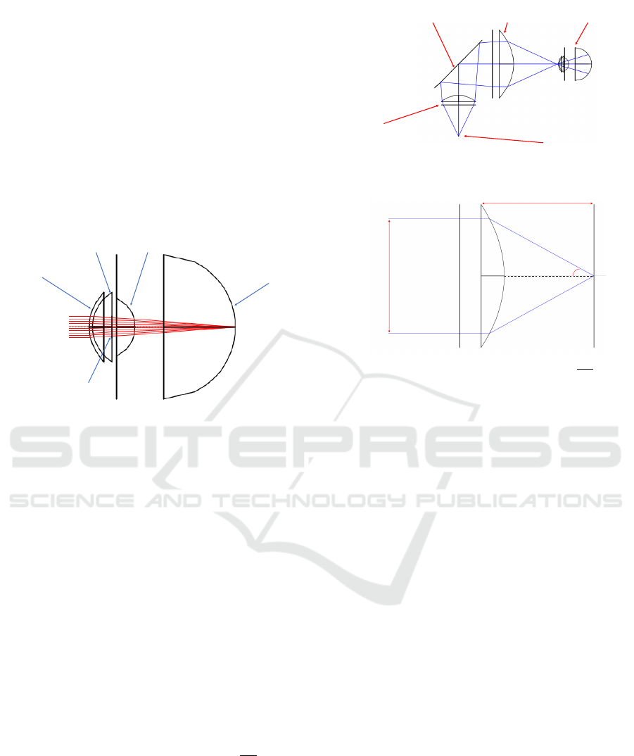
To simulate a Fundus Camera optical system, the
optical path taken by the rays is separated in two dif-
ferent ones by the usage of a beamsplitter (Tran et al.,
2012). The path that describes how the rays illu-
minate the retina is called illumination path and the
path describing how the rays go from the retina to the
smartphone camera is called imaging path. To sim-
ulate them two different approaches were tested, the
4-extreme model for the illumination, and the parallel
rays model for the imaging path (see Figure 2). The
4-extreme model assumes that the light source emits
BIODEVICES 2018 - 11th International Conference on Biomedical Electronics and Devices
64

from a single point with a certain aperture previously
declared by the manufacturer. The angles for which
the relative luminous intensity is bellow half the max-
imum intensity can be neglected.
Figure 2: Demonstration of the 4-extremes model along the
x-axis.
The parallel rays model assumes that when two
rays focused at some point reach a lens they are colli-
mated and leave the lens with the same direction and
parallel with each other. In Figure 3 one of the appli-
cations of this model is demonstrated, showing rays
focused at some point, leaving the pupil parallel.
Figure 3: Demonstration of the parallel rays model. In this
figure rays are focused on the retina, leaving the pupil col-
limated and parallel.
1.4 Related Work
Recently, the features of handheld Fundus Camera
prototypes have increased significantly when com-
pared with the traditional tabletop fundus cameras
(Tran et al., 2012), proving as an helpful instrument
in the diagnosis of many pathologies related with
the retina and facilitating telemedicine applications
(Quellec et al., 2016; Jin et al., 2017). This improve-
ment of the capabilities of handheld devices led to a
variety of different approaches. Some examples that
reflect the recent scientific development are:
• Nonmydriatic Fundus Camera Based on the Rasp-
berry Pi
R
Computer: Uses the Raspberry Pi
R
camera module coupled with a Condenser Lens
to perform fundus imaging with a very low pro-
duction cost (Shen and Mukai, 2017).
• Eye-Selfie: By using internal fixation points as
targets, it allows a self-performed acquisition of
the fundus photography, completely by the patient
(Swedish et al., 2015).
There are already, some fundus camera prototypes
available in the market but most, present one of the
following issues:
• Low Field Of View, as for the D-EYE ophthalmo-
scope (D-EYE S.r.l, ).
• Require pupil dilation, as for the Volk inView
(Volk Optical Inc., a).
• High price, as for the Volk Pictor Plus (Volk Op-
tical Inc., b).
The system we propose differs from the previous
approaches by using a smartphone for non-mydriatic,
high field-of-view retinal image acquisition. The use
of a smartphone instead of custom electronic devices
for image capture and processing allows a substan-
tial decrease in costs while allowing for a very high
image quality and resolution, thus guaranteeing the
cost-effectiveness of the overall solution.
2 TOOLS AND METHODS
2.1 Eye Model
To guarantee a satisfactory field-of-view, an accurate
model of the eye is needed. The eye has two refrac-
tive lenses, the cornea and the crystalline lens. Based
on the literature (Atchison and Smith, 2000) and fol-
lowing a similar approach to (Tocci, 2007), a model
of the eye was created in BEAM IV considering the
radius of curvature, diameter and asphericity coeffi-
cients of all the structures relevant for ray tracing. The
pupil has been designed with a 4 mm diameter to sim-
ulate a non-mydriatic acquisition with no visible light
and is coincident with the lens anterior surface. The
chromatic aberrations from the eye were neglected as
the change in diopters at different wavelengths were
not considered significant in the scope of this work
(Atchison and Smith, 2000).
The defined structures of the eye, as represented
in Figure 4, are:
• Corneal Anterior surface:
Diameter = 11.50 mm
Radius of Curvature = 7.75 mm
Asphericity coefficient = -0.2
• Corneal Posterior surface:
Diameter = 11.50 mm
Radius of Curvature = 6.8 mm
Asphericity coefficient = 0
Optical Design of a Compact Image Acquisition Device for Mobile Diabetic Retinopathy Screening
65
• Pupil/ Lens Anterior surface:
Diameter = 4 mm
Radius of Curvature = 10 mm
Asphericity coefficient = -0.94
• Lens Posterior Surface:
Diameter = 9 mm
Radius of Curvature = -6 mm
Asphericity coefficient = 0.96
• Retina:
Diameter = 24 mm
Radius of Curvature = 12 mm
Asphericity coefficient = 0
Anterior Cornea
Posterior Cornea
4 mm Pupil
Retina
Lens
Figure 4: BEAM IV simulation of the eye model used with
collimated rays being focused on the retina.
2.2 Illumination Path
For the illumination path the main goal is a 40
◦
field-
of-view with a uniform illumination of the retina. The
diagram of the illumination path is represented in Fig-
ure 5. The image is obtained using a white visible
LED but, to allow a non-mydriatic acquisition, a Near
Infrared (NIR) LED is used, helping the examiner to
perform alignment of the device with the eye and to
find the area of the retina to be imaged. As the NIR
LED is simply used for guidance, only the Visible
LED imaging and illumination capabilities were eval-
uated. As in most fundus cameras, there is a lens
above the light source to collimate the rays and an-
other lens to focus the rays (Tran et al., 2012). This
lens that focuses the rays before reaching the eye is
called objective lens and it is where the simulations
performed began. To obtain a field-of-view of 40
◦
there is a constraint that the relationship
W D
2 f
should
be equal to or larger than sin(20) (see Figure 6), where
W D stands for Working Diameter and f means the ef-
fective focal length of the lens.
The type of objective lens to choose should min-
imize spherical aberrations. This condition, coupled
with the required numerical aperture, makes Aspheric
lenses the only suitable option for the focusing of
the rays when reaching the retina. After searching
PCX Lens
Beamsplitter Aspheric Lens
Light Source
Eye Model
Figure 5: Illumination path and the description of the com-
ponents used.
Working
Diameter
Effective Focal Length
20º
Figure 6: For a 20
◦
half-angle the relationship
W D
2 f
should
be equal to or larger than sin(20).
for a lens that fits these requirements we opted to
use a Thorlabs aspheric lens with 50.00 mm diame-
ter, 40.00 mm focal length and SLAH-64 glass type,
placed 25 mm ahead to the right of the center of the
beamsplitter. For the collimation of the rays coming
from the light source, the used Condenser lens was an
Edmund Optics Plano-Convex Lens with 25.4 mm di-
ameter, 38.1 mm focal length and N-BK7 glass type,
placed 47 mm below the center of the beamsplitter.
To check the distance between the objective lens
and the human eye, the plane where the rays were in
focus was calculated. This plane is called the focal
plane and is where the circle of confusion is mini-
mum.
In a theoretically aberration free-system, this is
where the pupil should be placed. However, after test-
ing it, was observed that due to spherical aberrations,
the intermediate rays reached the optical axis further
than the extreme rays, so only 40% reached the retina.
This problem was solved by putting the pupil 5 mm
after the focal point of the extreme rays. Using this
different configuration, 90% of the emitted rays reach
the retina and the illumination profile is uniform, as
can be observed in Figure 7. The half-angle on the
retina calculated was 20.65
◦
leading to a total field-
of-view of 41.3
◦
.
In the previous diagrams, the simulated light
source emits on a single wavelength (486 nm). As
the white light emitted by the LED has a continuous
emission spectrum, measurements at the other end of
BIODEVICES 2018 - 11th International Conference on Biomedical Electronics and Devices
66
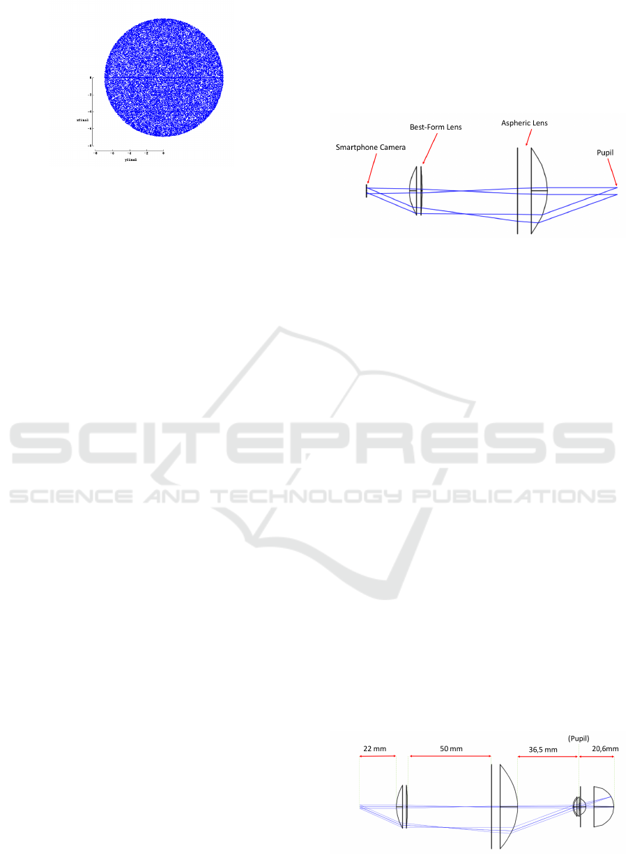
Figure 7: The retinal area illuminated, also called retinal
illumination profile, is described, for the configuration rep-
resented in Figure 5. The uniformity is noticeable.
the visible spectrum are needed. It was concluded that
for red light (656 nm) the system is also optimal with
92% of the rays reaching the retina with an half-angle
of 20.57
◦
, leading to a total field-of-view of 41.14
◦
.
2.3 Imaging Path
For the imaging path the key features desired are the
almost complete fulfillment of the Smartphone Cam-
era sensor and the minimization of aberrations.
In order to perform ray tracing analysis of the
imaging path, two pairs of parallel rays were consid-
ered, one pair parallel with the optical axis and the
other with 20
◦
inclination. The distance between the
rays, on each pair, was equal to the size of the pupil,
4 mm.
The system was optimized for a LG Nexus 5X
camera whose relevant specifications are:
• Horizontal Angle of View : 68.2
◦
• Vertical Angle of View : 53.1
◦
• Sensor Size : 1/2.3” (6.17 x 4.55 mm)
The final optical system must guarantee that the
Vertical Angle of View is mostly filled with the retinal
image, in order to allow the highest possible retinal
resolution, essential for the clinical analysis of fine
features. The first solution tested was with the As-
pheric Lens, described in section 2.2, as an Objective
Lens and with a Plano-Convex Lens with 40.0 mm of
focal length and 25.4 mm diameter serving as an Oc-
ular. The maximum diameter for the Plano-Convex
lens to fit the scope of a compact system was defined
to be of 25.4 mm. The system presented too much
aberrations and the rays did not reach the Smartphone
Camera parallel. To correct the aberrations, as the
Objective Lens already fulfilled the requirements for
the illumination path, the Ocular Lens was changed.
A Best-Form Lens with 40.0 mm focal length, 25.0
Diopters and 25.4 diameter was tested. The aberra-
tions were almost eliminated and the rays reached the
smartphone camera parallel to each other, with an in-
clination of approximately 22
◦
, leading to an angular
field-of-view of 44
◦
. The diagram can be seen in Fig-
ure 8. The angle in this configuration is inferior to the
achieved with the Plano-Convex lens as an ocular, but
still wide enough to avoid a significant crop.
Figure 8: The imaging path with a Best-Form Lens as the
Ocular Lens and an Aspheric Lens as the Objective, using
the parallel rays model.
In this setup the distance between the Smartphone
CMOS sensor and the Best-Form Lens is 22 mm. The
distance between the surface of the Best-Form Lens
with less curvature and the planar surface of the As-
pheric Lens is 50 mm and between the Aspheric lens
and the eye is 33 mm.
2.4 Imaging Path for Eyes with
Refractive Errors
Eyes with refractive errors present different optical
characteristics and so the distance between lenses in
the optical system must be adjustable to compensate
this.
As the smartphone camera is able to change its
focus target distance, the refractive errors were only
simulated in the range -5D to +5D. Since one of the
possible cause of refractive errors is the size of the
eyeball, for the modulation of Myopia the retina was
moved 3 mm away from the refractive center of the
eye. Concerning the modulation of Hyperopia the
eyeball was shortened 3 mm.
In Figure 9, the system configuration for an eye
without any refractive error is shown. In Figure 10
and Figure 11, diagrams showing the adjustments
done to compensate these refractive errors are shown.
Figure 9: The distances between each components to image
an eye without refractive errors.
Optical Design of a Compact Image Acquisition Device for Mobile Diabetic Retinopathy Screening
67
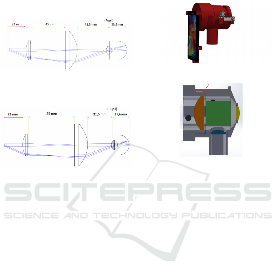
For the Myopic eye the error is corrected by mov-
ing the Objective Lens 5 mm away from the eye.
Figure 10: The distances between each components to im-
age an eye with refractive errors (Myopia).
Concerning the Hyperopic eye, the Objective lens
is approximated 5 mm to the eye.
Figure 11: The distances between each components to im-
age an eye with refractive errors (Hyperopia).
2.5 Mechanical Prototyping
The optical system previously described is to be im-
plemented in a 3D printed prototype. The design of
the mechanical prototype was developed using Solid
Works. The important goals for this prototype are to
allow the arrangement of the desired lens, a support
for the smartphone that ensures that the camera is cen-
tered with the optical path, and the adjustment of the
objective lens.
As can be seen in Figure 12, the movements of the
Objective are made with a Rack and Pinion system to
allow the examiner to precisely search for the working
distance, thus allowing the best possible focusing of
the retina.
Other solution to allow the movement of the lens
would be by the use of threaded surfaces in both sides,
so the rotation of the objective ensures a change in
the working distance. This approach was rejected be-
cause it is expected the future implementation of a
piece leaning against the patient forehead, to guaran-
tee the centering with the Optical Path. The rotation
of this piece, in contact with the patient, would not be
comfortable or, possibly, safe.
Figure 12: Mechanical prototype showing both the smart-
phone support and the rack and pinion mate.
Figure 13: Section view of the prototype. In blue is the
PCX Condenser Lens, in yellow the Best-Form Lens, in or-
ange the Aspheric Lens and in green the Beamsplitter. The
Beamsplitter is in the form of a cube only for simulation,
to simplify the fixation in the mechanical case. The small
piece highlighted by the red arrow limits the adjustment be-
tween the aspheric lens and the beamsplitter. The configu-
ration presented is for an eye with myopia.
3 RESULTS AND DISCUSSION
3.1 Complete System Designed
The Complete System presented in Figure 14 has the
following elements:
• Light Source (Visible or Near Infra-red LED).
• N-BK7 Plano-Convex Lens, 38.1 mm Focal
Length, 25.4 mm φ, VIS-NIR Coated, 44,00e,
Edmund Optics.
• S-LAH64 CNC-Polished Aspheric Lens, 40.0
mm Focal Length, 50 mm φ, 392,00e, ThorLabs.
• Beamsplitter 50R/50T 35x35 mm, (≈ 35,00 e).
• N-BK7 Best-Form Lens, 40 mm Focal Length,
25.4 mm φ, 39,00e, Thorlabs.
The utilization of aperture stops is dependent on
the LEDs beam angle. The aperture can be used to
stop the rays emitted by the LED at a wider angle than
the necessary for a field-of-view of 40
◦
, preventing
reflections and the imaging of undesired areas.
BIODEVICES 2018 - 11th International Conference on Biomedical Electronics and Devices
68
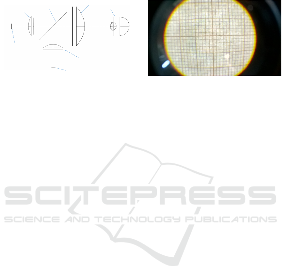
Smartphone Camera
Best-Form Lens
Light Source
PCX Lens
Beamsplitter
Aspheric Lens
Eye Model
Figure 14: Complete Optical System.
The main features of the developed system are:
• Around 40
◦
field-of-view.
• Non-Mydriatic Acquisition, for a 4 mm pupil size,
achievable by using the NIR LED for guidance.
• No significant aberrations (Spherical and Chro-
matic).
• Uniform Illumination of the Retina.
• Simple and affordable lens system.
3.2 Imaging Path Practical Tests
Some practical tests were performed on the Imag-
ing Path using an Optic Table. A 3.5 mm Iris was
used to simulate the pupil and a 38.1 mm focal length
Plano-Convex lens was used replacing the eye refrac-
tive center. For these tests, only the lights in the room
were used to illuminate the target, and this target was
a millimeter paper placed at 38 mm from the 38.1
mm Plano-Convex Lens. A black paperboard was
used, to prevent the loss of light to the environment
and undesired reflections. The smartphone used was
a Microsoft Lumia 650 with 63.4
◦
horizontal field-
of-view, 49.7
◦
vertical field-of-view and a 3.6 x 2.7
mm sensor size with an 8 Megapixels camera. It was
placed at 20 mm from the Best-Form Lens. The re-
sults, as shown in Figure 15, demonstrate a system
with only a few aberrations in the periphery but with a
good resolution at the center showing a field-of-view
of about 43
◦
.
The spatial resolution was also assessed. Consid-
ering an 8MP resolution camera, the captured pic-
ture has 3272 × 2454 pixels. As the horizontal res-
olution is superior, the calculations are presented for
the vertical resolution. Due to the crop in the vertical
field-of-view, the vertical half-angle of view will be
of about 17.5
◦
, which would correspond to 6.0 mm
in the retina. Thus, the spatial resolution is 4.9 µm,
meaning that each pixel contains 4.9 µm of the reti-
nal area, which is sufficient to observe the expected
smallest microaneurysms (25 µm). Still based in the
Figure 15: Image obtained by the Microsoft Lumia 650
smartphone demonstrating that at least the centered 15 mm
of the target could be imaged.
previous calculus, the usage of a smartphone camera,
instead of a higher resolution camera, is justified by
the eye diffraction limit. A much higher resolution
would be more expensive and the spatial resolution
would start to be close to the eye diffraction limit: for
a 5 mm pupil eye receiving light of about 500 nm,
this diffraction limit is 1.5 µm (Roorda and Duncan,
2015), close to the resolution calculated.
The quality of the image would be improved if the
used millimeter paper could be bent to describe more
accurately the retina and diminish spherical aberra-
tions.
3.3 Comparison with other Fundus
Cameras
The compact optical system described has a total
components cost of about e800, considering the ex-
ternal adapters for the good functioning of the optical
system. Fundus Cameras with similar field-of-view
and non-mydriatic acquisition, like the Volk Pictor
Plus, cost about e10000.
The features of the prototype, coupled with its
simplicity and relatively low price compare favorably
with the products currently available, can facilitate the
provision of healthcare world-wide, and make it an in-
teresting solution for under-developed countries.
4 CONCLUSIONS
It can be concluded that the optical system designed
showed satisfactory capabilities in experimental tests,
being able to detect the smallest lesions associated
with Diabetic Retinopathy. Moreover, it is expected
that in the future this device can be a reliable tool
in early-stage diagnosis and, indirectly, contribut-
ing to an improvement in the treatment of Diabetic
Retinopathy cases all over the world.
Optical Design of a Compact Image Acquisition Device for Mobile Diabetic Retinopathy Screening
69

The 3D-printing of the mechanical prototype de-
scribed in section 2.5 is expected to be further devel-
oped in future work, so that the implementation of the
optical system can be performed. After the prototype
construction, several ”in vivo” tests are expected.
A light hazard measurement, regarding the ISO
15004-2 (ISO 15004-2:2007, 2007) and ISO 10940
(ISO 10940:2009, 2009) norms, for this kind of in-
struments is also mandatory, being the first for light
hazard protection of Ophthalmologic Instruments and
the second specifically for Fundus Cameras.
ACKNOWLEDGEMENTS
We would like to acknowledge the financial support
obtained from North Portugal Regional Operational
Programme (NORTE 2020), Portugal 2020 and the
European Regional Development Fund (ERDF) from
European Union through the project Symbiotic tech-
nology for societal efficiency gains: Deus ex Machina
(DEM), NORTE-01-0145-FEDER-000026.
REFERENCES
Atchison, D. and Smith, G. (2000). Optics of the Human
Eye. Butterworth-Heinemann, page 259.
Benbassat, J., Polak, B. C. P., and Javitt, J. C. (2012). Ob-
jectives of teaching direct ophthalmoscopy to medical
students. Acta Ophthalmologica, 90(6):503–507.
Born, M. and Wolf, E. (1999). Principles of Optics (7th
Ed). Cambridge University Press.
Bunce, C. and Wormald, R. (2006). Leading causes of cer-
tification for blindness and partial sight in England &
Wales. BMC public health, 6:58.
Cheung, N., Mitchell, P., and Wong, T. Y. (2010). Diabetic
retinopathy. The Lancet, 376(9735):124–136.
Cunha-Vaz, J. (2007). Characterization and relevance of
different diabetic retinopathy phenotypes. Develop-
ments in Ophthalmology, 39:13–30.
D-EYE S.r.l. D-EYE Ophthalmoscope.
do Prado, R. S., Figueiredo, E. L., and Magalhaes, T. V. B.
(2002). Retinal detachment in preeclampsia. Arquivos
brasileiros de cardiologia, 79(2):183–186.
Giancardo, L. (2012). Automated fundus images analysis
techniques to screen retinal diseases in diabetic pa-
tients Docteur de l ’ universit
´
e Automated Fundus Im-
ages Analysis Techniques to Screen Retinal Diseases
in Diabetic Patients.
ISO 10940:2009 (2009). Ophthalmic instruments - Fun-
dus cameras. Standard, International Organization for
Standardization, Geneva, CH.
ISO 15004-2:2007 (2007). Ophthalmic instruments - Fun-
damental requirements and test methods.Part 2: Light
Hazard Protection. Standard, International Organiza-
tion for Standardization, Geneva, CH.
Jenkins, F. and White, H. (1957). Fundamentals of optics.
McGraw-Hill.
Jin, K., Lu, H., Su, Z., Cheng, C., Ye, J., and Qian, D.
(2017). Telemedicine screening of retinal diseases
with a handheld portable non-mydriatic fundus cam-
era. BMC Ophthalmology, 17(1):89.
Kauppi, T. (2010). Eye Fundus Image Analysis for Auto-
matic Detection of Diabetic Retinopathy.
Li, H., Esquivel, A., Davis, G., and Krupinski, E. (2006).
Evaluation of digital resolution for viewing diabetic
retinopathy microaneurysms.
Patton, N., Aslam, T., MacGillivray, T., Pattie, A., Deary,
I. J., and Dhillon, B. (2005). Retinal vascular image
analysis as a potential screening tool for cerebrovas-
cular disease: a rationale based on homology be-
tween cerebral and retinal microvasculatures. J Anat,
206(4):319–348. 15817102[pmid].
P
´
erez, M. A., Bruce, B. B., Newman, N. J., and Biousse,
V. (2012). The use of retinal photography in non-
ophthalmic settings and its potential for neurology.
Neurologist, 18(6):350–355. 23114666[pmid].
Phillips, C. I. (1984). Dilate the pupil and see the fun-
dus. Br Med J (Clin Res Ed), 288(6433):1779–1780.
6428541[pmid].
Quellec, G., Bazin, L., Cazuguel, G., Delafoy, I., Coch-
ener, B., and Lamard, M. (2016). Suitability of a low-
cost, handheld, nonmydriatic retinograph for diabetic
retinopathy diagnosis. Translational Vision Science &
Technology, 5(2):16.
Roorda, A. and Duncan, J. L. (2015). Adaptive op-
tics ophthalmoscopy. Annu Rev Vis Sci, 1:19–50.
26973867[pmid].
Salz, D. A. and Witkin, A. J. (2015). Imaging in diabetic
retinopathy. Middle East African journal of ophthal-
mology, 22(2):145.
Shen, B. Y. and Mukai, S. (2017). A portable, inexpensive,
nonmydriatic fundus camera based on the raspberry
pi
R
computer. Journal of Ophthalmology, 2017(3):5.
Swedish, T., Roesch, K., Lee, I., Rastogi, K., Bernstein, S.,
and Raskar, R. (2015). eyeselfie: Self directed eye
alignment using reciprocal eye box imaging. ACM
Trans. Graph., 34(4).
Tarr, J. M., Kaul, K., Chopra, M., Kohner, E. M., and Chib-
ber, R. (2013). Pathophysiology of Diabetic Retinopa-
thy. ISRN Ophthalmology, 2013:1–13.
Tocci, M. (2007). How to model the human eye in zemax.
Tran, K., Mendel, T. A., Holbrook, K. L., and Yates, P. A.
(2012). Construction of an inexpensive, hand-held
fundus camera through modification of a consumer
”point-and-shoot” camera. Investigative ophthalmol-
ogy & visual science, 53 12:7600–7.
Volk Optical Inc. Volk InView.
Volk Optical Inc. Volk Pictor Plus.
BIODEVICES 2018 - 11th International Conference on Biomedical Electronics and Devices
70
