
Translating Multi-device Task Models to State Machines
Andreas Wagner
1
and Christian Prehofer
2
1
itestra GmbH, M
¨
unchen, Germany
∗
2
fortiss GmbH, M
¨
unchen, Germany
Keywords:
Task Models, Multi-device UI, Cross-device UI, Model-based Development, Multi-device Applications.
Abstract:
This paper presents an approach for translating multi-device task models to a distributed execution model
based on state machines. We consider an expressive extension to ConcurTaskTrees, called multi-device Con-
curTaskTrees (MCTTs) as a modeling language for distributed multi-device applications. We use the device
labeling operators Any and All, which specify if user interactions at runtime shall take place on one or all of
a set of devices and extend the translation algorithm for “classical” CTT operators with translation rules for
these multi-device operators in a distributed setting. Our algorithm exploits concurrent and hierarchical state
machines for the execution and the concept of partial state machines during the translation.
1 INTRODUCTION
With the increasing number of hardware and software
platforms, model-driven software-engineering meth-
ods have become a widely used tool in systems devel-
opment. In this paper, we focus on the model-driven
design of applications which offer users interaction
possibilities with multiple devices in a distributed set-
ting. A common tool for model-based design of inter-
active applications are ConcurTaskTrees (CTTs) (Pa-
tern
`
o, 2000), which model how activities can be per-
formed in an interactive application and describe re-
lations between the distinct tasks on an abstract level.
CTTs as such however do not cover distributed exe-
cution of tasks, only annotations of devices to tasks
are possible in some implementations, see e.g. (Pa-
tern
`
o et al., 2010). Several researchers have consid-
ered such “multi-device applications”, which connect
multiple devices to work collaboratively at the same
time, e.g. (Chmielewski, 2014; R
¨
adle et al., 2015).
One approach which also considers dynamic task al-
location at runtime is Multi-Device ConcurTaskTrees
(MCTT) (Prehofer et al., 2016). MCTTs introduce
new tree operators Any and All, which specify how
tasks can be mapped to devices. Furthermore, they
specify user interactions which might occur on several
devices during runtime in a flexible way. With Any, a
(complex) interaction can take place at one of multi-
ple devices, while All requires an interaction to take
∗
Research carried out at Technische Universit
¨
at
M
¨
unchen, Germany
place at all specified devices. The All operator is of-
ten used for output actions which shall take on all de-
vices, while Any can be used to select an input device
at runtime. Clearly, this requires a significant amount
of runtime coordination among devices as each sub-
tree of a MCTT can be labeled in this way.
It has been shown that CTTs can be translated
into efficiently executable state machines (Wagner
and Prehofer, 2016; Wagner, 2015), which preserve
the defined semantics of the CTT operators (Wag-
ner and Prehofer, 2016). In this paper, we extend
this translation to the multi-device case by introduc-
ing translation rules for the MCTT operators. These
state machines might be used to control (distributed)
user interfaces or even whole devices.
2 MULTI-DEVICE TASK
MODELS
Multi-Device CTTs (Prehofer et al., 2016) extend
classical CTTs by means of two new operators,
namely Any and All, which are called device labeling
operators and are used for specifying devices within a
MCTT. These operators primarily attach a list of de-
vice identifiers to a CTT, a subtree within a CTT or a
single task. A device in this context may be a physical
or logical entity, with input and/or output capabilities
and the ability to execute some kind of logic.
While the original CTT operators (e.g. En-
420
Wagner, A. and Prehofer, C.
Translating Multi-device Task Models to State Machines.
DOI: 10.5220/0006604704200428
In Proceedings of the 6th International Conference on Model-Driven Engineering and Software Development (MODELSWARD 2018), pages 420-428
ISBN: 978-989-758-283-7
Copyright © 2018 by SCITEPRESS – Science and Technology Publications, Lda. All r ights reserved

Table 1: Overview of CTT operators and the MCTT exten-
sions.
Operator Symbol Definition
Ch(α
1
,α
2
) [] Choice: One of the two
choices is taken at run time.
Co(α
1
,α
2
) ||| Concurrent: CTTs α
1
and
α
2
are performed concur-
rently, with any interleav-
ing of sub-tasks.
Di(α
1
,α
2
) [> Disabling: The CTT α
1
is
executed and can be inter-
rupted at any time by α
2
.
Execution continues in α
2
.
En(α
1
,α
2
) >> Enabling: The CTT α
2
starts after the CTT α
1
.
MCTT Extension
Any
c
1
,...,c
i
(α) Any(...) Any: The CTT α is exe-
cuted on one of the devices
c
1
,...,c
i
.
All
c
1
,...,c
i
(α) All(...) All: The CTT α is exe-
cuted on all of the devices
c
1
,...,c
i
.
abling, Disabling or Choice) describe a set of pos-
sible sequences of basic tasks to achieve the overall
goal (Br
¨
uning et al., 2008), device labeling operators
introduce a spatial domain into the task model (Pre-
hofer et al., 2016). This is achieved due to dynamic
assignment of tasks to an arbitrary subset of devices
at runtime. The operators Any and All hereby define
the execution semantics, i.e. if a task or task config-
uration should be executed mutually exclusive on one
device (Any) or in parallel on several devices (All).
MCTTs are best suited for distributed scenarios
where a set of tasks should be executed on a multi-
tude of devices. A unique characteristic of the MCTT
notation is that it treats device labeling operators just
like regular CTT operators. Thus, they can be placed
arbitrarily within the task tree. In particular, this also
allows for nesting these operators. This is especially
useful in cases where arbitrary devices can be selected
for the execution of a complex task set, but one or
more sub task(s) must always be mapped on a spe-
cific device (this is then called a device labeling ex-
ception (Prehofer et al., 2016)).
The MCTT notation preserves the task types of
CTTs as introduced in (Patern
`
o, 2000). It supports
User tasks, which are cognitive/perceptive and don’t
require interaction with the system, Interaction tasks,
which describe any kind of user interaction, e.g. pro-
viding inputs or clicking a button and Application or
System tasks, which the system performs without any
additional user interaction. Abstract tasks are sup-
ported as well.
Table 1 shows the CTT operators used through-
out this work as well as the device-labeling operators.
Any
mi,mo
>>
I setHour >>
I setMinute >>
I setSeconds [>
I con f irmTime I resetTime
Figure 1: Example of a simple (binary) MCTT for config-
uring a timer.
For the purpose of this paper, we only use the shown
subset of the CTT notation.
An example of a MCTT can be found in Figure
1. It describes how a user would configure an alarm
clock, e.g. for a microwave with an additional remote
device like a smartphone app. The surrounding Any
operator defines two devices mi (microwave) and mo
(mobile device). According to the semantics of Any,
the configuration process can either be started on mi
or mo, but once started on one device, it must also be
finished on the selected device.
3 TRANSLATION TO STATE
MACHINES
The translation of MCTTs into state machines is
based on the recursive algorithm for CTT translation
presented in (Wagner and Prehofer, 2016). This al-
gorithm is based on so-called Partial State Machines
(PSMs). These are captured as Connectables and a
connect operator to compose them. We use translation
rules for the “classical” CTT operators to correspond-
ing PSMs as detailed in (Wagner, 2015). For instance,
an Enabling operator is defined as a concatenation of
the corresponding partial state machines for its sub-
trees α
1
and α
2
. Contrarily, a Choice operator is de-
fined as the union of its subtrees’ PSMs. Disabling
and Concurrent operators are basically mapped to hi-
erarchical and concurrent (parallel) states which in
turn will be used for subsequent transformations. For
a detailed and formal definition of these concepts we
refer to (Wagner and Prehofer, 2016) and (Wagner,
2015).
The novelty in this work is the distributed device
setting, which requires coordination and synchroniza-
tion among devices. Therefore, we assume a model
where all devices are fully synchronized and aware
of the status of other devices. For this purpuse, we
Translating Multi-device Task Models to State Machines
421

Device 1
Statechart
Device 2
Statechart
Device n
Statechart
Device 3
Statechart
System
Event x
occured
Event x
Coordinator
Event x
Figure 2: The global system execution model which is as-
sumed for the state machine generation.
generate a state machine for each device which re-
flects the global system state. This means that the
state machine for a specific device also includes states
and transitions for all the other devices in the sys-
tem. These “shadow devices” are used for coordi-
nation during a local device’s idle phase while other
devices are active.
Due to our distributed execution, the implementa-
tion of Any and All needs to use and generate implicit
information about required notifications. A notifica-
tion is basically implemented as a state transition in
the generated state machines and its concept is based
on a global execution model which is depicted in Fig-
ure 2. The basic idea is, that the state machine of each
device whose label is present in the label set of an Any
or All operator, also is aware of and follows all states
and transitions which are actually executed on other
devices. This implies that all events that might occur
on any of the defined devices result in state changes
on all involved state machines.
Further, we assume a central coordinator where all
communication between devices is routed over. If an
event is generated on a device (e.g. because the user
executes an interaction task), the device forwards the
event to the coordinator. The coordinator broadcasts
the event to all other state machines in the system. If
two devices emit events simultaneously, the coordi-
nator decides about the event to be broadcasted. Con-
sequently, an event will lead to a state transition in
every state machine and the Any and All operators are
executed synchronously on all involved devices.
In the formalization below, the translation will
have the two new parameters physical target and vir-
tual target. The physical target is the device we ac-
tually want to create the state machine for. Conse-
quently, this parameter won’t change during the trans-
lation run for an actual device. Contrarily, virtual tar-
get reflects the aforementioned “shadow devices” and
might change during the translation (e.g. if the al-
gorithm handles subtrees which are defined to be ex-
ecuted on remote devices). Initially, physical target
and virtual target are equal.
For simple tasks, we reuse the translation rules
described in (Wagner and Prehofer, 2016). Conse-
quently, an application task will always be translated
into a basic state with a so-called notification tran-
sition appended. Accordingly, interaction tasks will
always be translated into transitions.
However, because of the semantics of Any and All
operators, we can no longer assume one-to-one re-
lationship between the task and the generated state
machine element as it is in a non-distributed envi-
ronment. Thus, in order to make states and transi-
tions uniquely identifyable, we add a device label to
the transition or state. For transitions, we always ap-
pend the virtual target to the transition’s event name.
For instance, if we want to translate an interaction
task “pushButton” which should be executed on a de-
vice x (because the task was labeled with e.g. Any
x
),
the resulting transition would have the event name
pushButton
x. The actual value of “virtual target”
is determined by the translation rules for the device
labeling operators Any and All, which we will show
later in this section.
The translation of application tasks must be mod-
ified as well. The main issue here is that we have to
distinguish whether or not the task is available on the
current device. In any case, we have to create a ba-
sic state with a notification transitition attached. The
state name itself depends on the current virtual target.
If it is equal to the physical target, we know that the
task must be executed locally and thus create a state
called “< taskname virtualtarget >”.
If the virtual target is different from the physical
target, we know that the current device has to wait
for the completion of the task on a remote device. We
therefore have to put the state machine in an idle state.
We call these idle states nop states, which indicates
that these states do not execute tasks (“no operation”).
We know that when the state machine of a device is in
nop states, at least one other (remote) device performs
a task at the same time. In order to be able to leave
the nop state, we attach a notification transition named
“< taskname f inished virtualtarget >”. If this event
occurs, the local device knows that the remote device
has finished task execution and its local state machine
can move on.
As an example, consider an application task
“senseTemperature” which should be executed on de-
vice x (e.g. the task was labeled with Any
x
, so x
is the current virtual target). The state machine is
created for x, which makes x the current physical
target. Consequently, the generated state has the
MODELSWARD 2018 - 6th International Conference on Model-Driven Engineering and Software Development
422

form “senseTemperature x” with an outgoing transi-
tion “senseTemperature finished x”.
If we create the state machine for device y (which
would then be the physical target), the resulting
state would be “nop y” with an outgoing transition
“senseTemperature finished x”. Note that this trans-
lation schema might lead to many nop states within a
state machine. In order to avoid naming conflicts, we
add additional unique IDs to each nop state’s name.
3.1 Translation of Device Labeling
Operators
The device labeling operators provide information on
which devices tasks are to be executed. The Any oper-
ator followed by a task subtree α is defined to execute
the subtree on one and only one of the given devices.
If the subtree was entered by one of the defined de-
vices (e.g. device x), the other devices defined within
the context of the operator are not allowed to perform
tasks until the subtree was fully executed by x, or un-
til another device (e.g. y) must be activated due to a
labeling exception defined for y.
From a semantical point of view, Any is similar
to a Choice, but with an arbitrary number of alter-
natives (i.e. the number of labels Any is annotated
with). As an example, consider Figure 3. A MCTT
consisting of three tasks which are connected via En-
abling operators is labeled with Any
x,y
. This leads to
two possible execution paths. Either “clickButton”
is executed on device x, then, “timerCountdown” and
“alarm” must also be executed on device x and de-
vice y must not perform any of the tasks. Option
two requires “clickButton” to be executed on device
y. Then, “timerCountdown” and “alarm” must also be
executed on device y, but device x must not perform
any of the tasks. Considering device x, the MCTT in
Figure 3 thus acts as a Choice. Either “clickButton” is
executed locally, which implies that subsequent tasks
must also be executed locally, or “clickButton” is ex-
ecuted by device y, which implies that x must neither
execute “clickButton” nor any of the other subsequent
tasks.
However, one has to decide what device x is ex-
pected to do when “clickButton” occurs on device y.
One possible solution (which is also employed by our
translation rule) is, that x simply follows the execution
of y but does not execute tasks locally. Instead, it en-
ters representational states (nop states) and performs
representational transitions which correspond to the
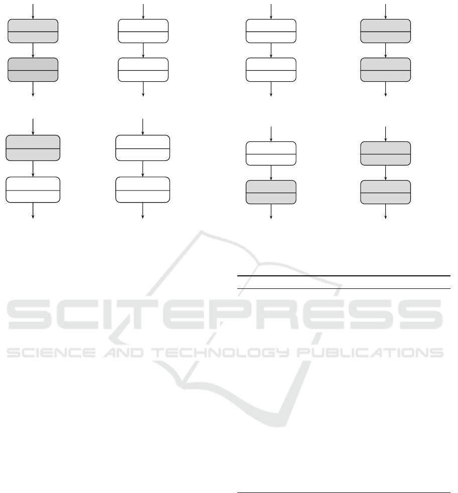
actual execution on device y. Figure 5(a) and Figure
5(b) show this behavior for the MCTT in Figure 3 by
means of partial state machines. One can recognize
that states and transitions for both x and y are always
Any
x,y
>>
I clickButton >>
A timerCountdown A alarm
Figure 3: MCTT representing an Any operator without la-
beling exceptions.
Any
x,y
>>
I clickButton >>
A timerCountdown Any
y
A alarm
Figure 4: MCTT representing an Any operator with labeling
exceptions.
part of both devices. However, events and state names
depend on the selected execution path. For example,
if “clickButton” was chosen on device x, x follows the
gray colored path, whereas y follows the white col-
ored path. White states on y are only nop states, as y
must not execute task-related functions.
Similarly, we can treat labeling exceptions in
a MCTT. For example, let’s assume that the task
“alarm” must always be executed on device y, even
if previous tasks were executed on device x, i.e. the
MCTT has a subtree Any
y
(alarm) (Figure 4). Again,
we have two possible execution paths. Option one
requires “clickButton” to be executed on device x.
Then, “timerCountdown” must also be executed on
device x but “alarm” must be executed on device y.
Option two implies that “clickButton” is executed on
device y. Then, “timerCountdown” and “alarm” must
also be executed on device y.
The resulting partial state machines are shown in
Figure 5(c) and Figure 5(d). In this case, the PSM for
device x does not have a state with name “alarm x”
but only a nop state. This ensures that the task “alarm”
is never executed on x. Instead, the PSM for y has the
state “alarm y” in both of its execution paths. This
ensures that the task’s associated implementation is
always executed on y, even if “clickButton” was ini-
tially performed on device x. Note that both devices
communicate by the exact same events.
The formal steps of translating an Any operator
are shown by algorithm 1. Note that we reuse exist-
ing translation rules for simple tasks and CTT trans-
lators. The Any translation orchestrates this by gener-
Translating Multi-device Task Models to State Machines
423
timerCountdown_x
alarm_x
clickButton_x
timerCountdown_finished_x
nop_1_y
nop_2_y
timerCountdown_finished_y
clickButton_y
alarm_finished_yalarm_finished_x
(a) Device x without labeling exception.
nop_1_x
nop_2_x
clickButton_x
timerCountdown_finished_x
timerCountdown_y
alarm_y
timerCountdown_finished_y
clickButton_y
alarm_finished_x
alarm_finished_y
(b) Device y without labeling exception.
timerCountdown_x
nop_1_x
clickButton_x
timerCountdown_finished_x
nop_1_y
nop_2_y
timerCountdown_finished_y
clickButton_y
alarm_finished_yalarm_finished_y
(c) Device x with labeling exception.
nop_1_x
alarm_y
clickButton_x
timerCountdown_finished_x
timerCountdown_y
alarm_y
timerCountdown_finished_y
clickButton_y
alarm_finished_y
alarm_finished_y
(d) Device y with labeling exception.
Figure 5: Concept of “nop” states in partial state machines. White states are never actually executed on the local device.
Instead, they act as synchronization points during state machine execution.
ating distinct PSMs for each of its defined labels and
returning a merged PSM as result. Lines 8 to 13 it-
erate over all defined labels of the Any operator and
generate a PSM for the current label by applying the
translation function f to the subtree α. During this
step, the virtual target parameter is set to the device
label belonging to the current iteration. The algorithm
then knows whether tasks must be executed locally or
will be executed remotely. Consequently, it can gen-
erate correctly annotated (nop) states and transitions.
Finally, a container PSM
Any
must be created (lines
14 to 18), which explicitly specifies the input and
ouput events of the PSM (see (Wagner, 2015) for de-
tails). The in set, out set and states set of PSM
Any
consist of their merged counterparts of all generated
PSM
l
.
3.1.1 All Operator (All
c
1
,...,c
n
(α))
The All operator enforces execution of the subtree α
on all defined labels/devices. This requires synchro-
nization at the end of α, so it may only be fully ex-
ecuted if all involved devices reach one of the tasks
contained in last(α).
The All operator is translated similar to the Con-
current operator (see (Wagner and Prehofer, 2016)).
The basic idea is that the All operator is translated
into a concurrent state with a (hierarchical) substate
for each label defined in the label set L of the operator.
One of these substates represents the actual execution
on the current device, the other ones are acting as
Algorithm 1: Translation of the Any Operator.
1: function F(mctt, virtual target, physical target)
2: if mctt is Any(α) then
3: // initialize sets for result PSM container
4: inConnectables, allStates, outStates ←
/
0
5: allStates ←
/
0
6: outStates ←
/
0
7: // Build PSM for α for each label
8: for all l ∈ labels(mctt) do
9: PSM
l
← F(α, l, physical target)
10: inConnectables ← inConnectables ∪ in(PSM
l
)
11: allStates ← allStates ∪ states(PSM
l
)
12: outStates ← outStates ∪ out(PSM
l
)
13: end for
14: create PSM container PSM
Any
15: in(PSM
Any
) ← inConnectables
16: out(PSM
Any
) ← outStates
17: states(PSM
Any
) ← allStates
18: return PSM
Any
19: end if
20: end function
“shadow devices” (or proxy machines) for the remote
execution. These proxies perform only nop states
(just like for the Any operator, but concurrently and
not mutually exclusive). We use these proxies, be-
cause the concurrent state representing the execution
of All may only be in its own final state if all remote
state machines have reached one of their final states as
well, i.e. they executed a task of the last set of α. Due
to our execution model, we can recognize such remote
events and advance the local proxy state machines ac-
cordingly. Thus, every concurrent proxy substate is
MODELSWARD 2018 - 6th International Conference on Model-Driven Engineering and Software Development
424

aware of the global system state.
In order to be able to detect every single event in
the first set of α, the algorithm must create a state con-
figuration for each possible way of entering α. Sim-
ilar to the translation of the Concurrent operator, we
achieve that by creating several concurrent states (one
for each label), where each of the concurrent states
in turn contains a hierarchical (proxy) state for each
label. Altogether, this leads to a total number of n
2
hierarchical states, where n = |labels(All)|.
We explain the necessity of generating n
2
hierar-
chical states by means of an example. Let’s assume
a simple configuration with two tasks ”TaskA“ (inter-
action task) and ”TaskB“ (application task) which are
connected with an Enabling operator. The whole tree
is labeled with All
x,y
. According to the semantics of
All, both “TaskA” and “TaskB” must be executed by
device x and device y concurrently.
Intuitively, we would generate only one concur-
rent state with n hierarchical sub states - one for x and
one y. However, Figure 6(a) shows a problem (i.e.
a race condition) which will occur during runtime.
Let’s assume we observe device x during execution
and “TaskA y” is the first event that is detected by x.
Then, the PSM of x will enter the concurrent state via
transition “TaskA y”. Now “TaskA x” cannot be rec-
ognized anymore and the execution semantics of All
is violated.
The solution for this problem is to generate n
2
hierarchical states instead, which is depicted in Fig-
ure 6(b). Because there are two concurrent states
which have unique ingoing transitions, both events
“TaskA x” and “TaskB y” can be processed indepen-
dently. For example, if event “TaskA x” was sensed
by device x first, the state machine enters Parallel
1
x.
From there it is still possible to process the event
“TaskA y” and we preserve the semantics of All.
The formal translation steps of the All operator are
shown by algorithm 2. To create concurrent states
with hierarchical proxy states for each label, the algo-
rithm performs a nested loop over the labels of the All
operator (lines 6 and 9). Within the nested loop, the
algorithm creates partial state machines PSM
sublabel
by means of the translation function f . Thus, we reuse
already existing translation rules for basic tasks and
CTT operators (and also nested Any operators). Note
that PSMs are always created for the current label of
the inner loop (line 10). This ensures that states and
transitions are created with the right labels (i.e. vir-
tual targets), so that they represent the corresponding
device correctly.
In the next step, the algorithm decides if the en-
tering transitions must be extracted or encapsulated
in a hierarchical state. The decision is based on the
label variables of the outer and inner loop (line 11).
If the labels are equal, the entering transitions will
be extracted and later used as ingoing transitions for
the concurrent state. For this purpose, PSM
sublabel
is
equipped with final states, resulting in PSM
sublabel
f inal
.
From PSM
sublabel
f inal
, all transitions of the in set are
extracted. The rest of PSM
sublabel
f inal
is wrapped into
a hierarchical state and saved together with the ingo-
ing transitions (lines 13 to 17).
If the labels are not equal, the entering transi-
tions will not be extracted but encapsulated in a hi-
erarchical state. This results in a new state machine
PSM
sublabel
exec
. PSM
sublabel
exec
is then wrapped into a
hierarchical state and saved (lines 18 to 22).
When all labels of the inner loop are processed, a
concurrent state P is created, which contains all hier-
archical states built during the inner loop. P is then
equipped with a completion transition (i.e. a tran-
sition which we expect to be called by the runtime
as soon as all hierarchical states have reached a final
state) and saved together with ingoing transitions of
its hierarchical states (lines 25 to 30).
The result of the outer loop is a set of concurrent
states, with each concurrent state having a set of in-
going transitions. These concurrent states, their in-
going transitions and their completion transitions are
returned as resulting PSM
All
(lines 32 to 35).
3.2 Example
We show the applicability of the presented approach
by a simple alarm system. It can be configured by
both a hardware appliance (in the following denoted
as hw) and a smartphone (in the following denoted
as sp). The hardware device takes care about all the
sensing and surveillence. If it detects anything ma-
licious, an alarm should be raised on all devices, i.e.
both the hardware device and the smartphone. The
alarm must then be confirmed on all devices.
The MCTT for this application is shown in Figure
7. It presents the basic structure of the system, in-
cluding all the possible tasks and their relations. The
whole configuration is annotated with an Any opera-
tor to indicate that the setup can be started by either
the smartphone or the appliance. However, only the
appliance can perform the sensing part, thus we an-
notate the task with a labeling exception Any
hw
. If the
sensing task is finished
2
, the system should execute
an alarm task. We assume the alarm task to be infi-
nite, so we wrap it into a Disabled operator to be able
to cancel the task. The whole alarm subtree is labeled
2
We don’t provide any details here on when or how the
sensing task is finished. This remains for to the actual im-
plementation.
Translating Multi-device Task Models to State Machines
425

Parallel_x
TaskA_x
TaskB_x
TaskB_finished_y
done.state.Parallel_x
nop_y
TaskB_finished_x
TaskA_y
(a)
Parallel
1
_x
TaskA_x
TaskB_x
TaskB_finished_y
done.state.Parallel
1
_x
nop_y
TaskB_finished_x
TaskA_y
Parallel
2
_x
TaskA_y
TaskB_x
TaskB_finished_y
done.state.Parallel
2
_x
nop_y
TaskB_finished_x
TaskA_x
(b)
Figure 6: In order to preserve the execution semantics of All, n
2
hierarchical (sub) states must be created, where n is the
number of labels All is annotated with (PSMs were created for device x).
Algorithm 2: Translation of the All Operator.
1: function F(mctt, virtual target, physical target)
2: if mctt is All(α) then
3: inConnectables, allStates, outConnectables ←
/
0
4:
5: // Build a separate parallel state for each label
6: for all label ∈ labels(mctt) do
7: inTransitions, compounds ←
/
0
8: // Build proxy compound states
9: for all sublabel ∈ labels(mctt) do Build PSM for α
10: PSM
sublabel
← F(α, sublabel, physical target)
11: if label = sublabel then
12: // Extract ingoing transitions
13: PSM
sublabel
f inal
← CreateFinalStates(PSM
sublabel
)
14: transitions
sublabel
← transitions of in(PSM
sublabel
f inal
)
15: C ← Compound(states(PSM
sublabel
f inal
), sublabel)
16: compounds ← compounds ∪ {C}
17: inTransitions ← inTransitions ∪ transitions
sublabel
18: else
19: // Pack into compound state with ingoing transitions
20: PSM
sublabel
exec
← CreateExecutionClosure(PSM
sublabel
)
21: C ← Compound(states(PSM
sublabel
exec
), sublabel)
22: compounds ← compounds ∪ {C}
23: end if
24: end for
25: P ← ParallelState(parname, compounds, physical target)
26: t
completion
← Transition(“done.state. < parname >”, physical target)
27: P
connect
−→ t
completion
28: allStates ← allStates ∪ {P}
29: outConnectables ← outConnectables ∪ {t
completion
}
30: inConnectables ← inConnectables ∪ inTransitions
31: end for
32: create PSM container PSM
All
33: out(PSM
All
) ← outConnectables
34: states(PSM
All
) ← allStates
35: return PSM
All
36: end if
37: end function
with All
sp,hw
in order to indicate that both the alarm
and the confirmation must occur on all devices.
The resulting state machines for both devices sp
and hw are depicted in Figure 8. One can observe that
the state machine for device sp includes nop states
for the labeling exception Any
hw
(sense). Thus, sp
Any
sp,hw
>>
I setupParameters >>
I activate >>
Any
hw
A sense
All
sp,hw
[>
A alarm A con f irmAlarm
Figure 7: The MCTT of the alarm system example.
is in an idle state while device hw is in the sense
state. sp will wake up as soon as it detects the event
sense f inished hw. Note that it doesn’t matter if the
setupParameter and activate tasks were executed on
sp or hw - the wakeup of sp is guaranteed in any case.
Another aspect of the translation which we want
to explain in more detail is the result of the subtree
labeled with All
sp,hw
. For both devices, our algorithm
generates two concurrent states (one for each possible
execution paths). Within a concurrent state, we have
a hierarchical state for each device in the device set
of the All operator. Depending on the actual device
we created the state machine for, we have different
nop state combinations. For example, the hierarchical
states on device sp have nop states for alarm states
of device hw and vice versa. In principle, sp is only
interested in notification events from hw in order to
synchronize the state transitions.
This example clearly presents the essence of our
approach: The state machines of all involved devices
are executed in a completely synchronized manner.
Thus we can achieve a distributed, but coordinated ex-
ecution of the desired system behavior, which in turn
preserves the defined semantices of both CTT and la-
beling operators.
MODELSWARD 2018 - 6th International Conference on Model-Driven Engineering and Software Development
426
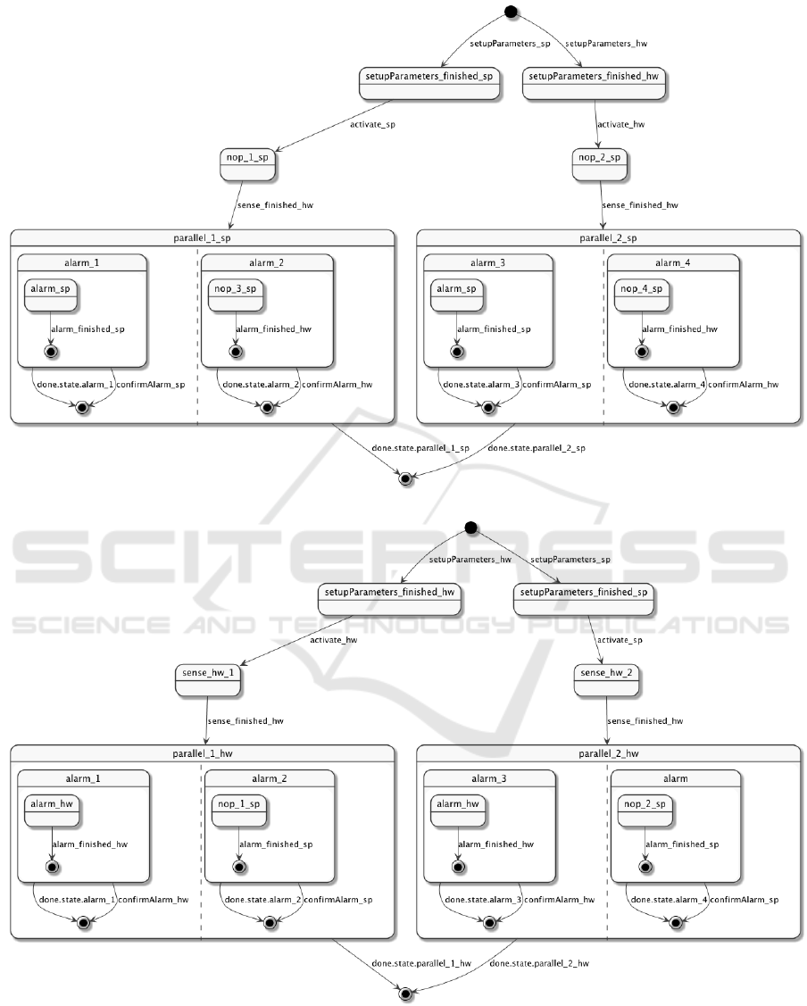
(a) State machine for device sp.
(b) State machine for device hw.
Figure 8: Generated state machines for the alarm system example.
Translating Multi-device Task Models to State Machines
427

4 RELATED WORK
Task models are often used for model-based user in-
terface development (MBUID), and many researchers
have investigated how task models support multi-
device applications development in ambient intelli-
gence environments. E.g. the work in (Patern
`
o et al.,
2010) exploits the web service annotation for model
transformations at various abstract levels. However,
designers have to create a distinct CTT for each de-
vice to connect them with the web services in order to
develop different versions of the same application on
multiple devices.
Luyten and Clerckx develop an algorithm for
transforming a CTT to executable state machines
(Luyten and Clerckx, 2003). This is similar to the
state machines used here, but does not consider multi-
device environments. More recent work like (Popp
et al., 2013) considers code generation for multi-
device UIs, but does not consider flexible constructs
like our Any or All operators.
In summary, we are not aware of any work sim-
ilar to this approach. Usually, all these existing ap-
proaches handle distribution issues in more concrete
models after defining the task models. In our opin-
ion, it is however natural to consider the distribution
to devices in task models directly. Instead of adding
rules for executing tasks across multiple devices at the
concrete model level, our introduced device labeling
mechanism enables designers to define execution of
tasks at the early stage.
5 CONCLUSION
In this paper, we have presented a first approach
to translate multi-device task models into distributed
state machines. The main novelty of this work is
an algorithm for the MCTT device labeling operators
Any and All, which creates distributed, coordinated
state machines in a multi-device setting. To achieve
this, we generate specific state machines for each in-
volved device which include states and transitions for
both tasks and necessary coordination overhead. We
build upon an already existing translation algorithm,
that translates ordinary CTT tasks and operators into
state machines. Our approach therefore extends the
translation of basic tasks and integrates the distributed
characteristics of device labeling operators into the
translation rules for CTTs. Overall, our paper shows
that MCTTs are a valid tool to build distributed, coor-
dinated systems with a mulitude of devices.
ACKNOWLEDGEMENTS
This work has been partly funded by German Min-
istry of Education and Research (BMBF) in the CrESt
project under grant number 01Is16043A.
REFERENCES
Br
¨
uning, J., Dittmar, A., Forbrig, P., and Reichart, D.
(2008). Getting SW engineers on board: Task mod-
elling with activity diagrams. Lecture Notes in Com-
puter Science (including subseries Lecture Notes in
Artificial Intelligence and Lecture Notes in Bioinfor-
matics), 4940 LNCS:175–192.
Chmielewski, J. (2014). Device-independent architecture
for ubiquitous applications. Personal and Ubiquitous
Computing, 18(2):481–488.
Luyten, K. and Clerckx, T. (2003). Derivation of a dialog
model from a task model by activity chain extraction.
Interactive Systems. Design . . . , pages 203–217.
Patern
`
o, F. (2000). Model-Based Design and Evaluation of
Interactive Applications. Springer-Verlag London.
Patern
`
o, F., Santoro, C., Spano, L. D., and CNR-ISTI, H.
(2010). User task-based development of multi-device
service-oriented applications. In AVI, page 407.
Popp, R., Raneburger, D., and Kaindl, H. (2013). Tool sup-
port for automated multi-device gui generation from
discourse-based communication models. In Proceed-
ings of the 5th ACM SIGCHI Symposium on Engineer-
ing Interactive Computing Systems, EICS ’13, pages
145–150, New York, NY, USA. ACM.
Prehofer, C., Wagner, A., and Jin, Y. (2016). A model-based
approach for multi-device user interactions. In Pro-
ceedings of the ACM/IEEE 19th International Con-
ference on Model Driven Engineering Languages and
Systems, pages 13–23. ACM.
R
¨
adle, R., Jetter, H.-C., Schreiner, M., Lu, Z., Reit-
erer, H., and Rogers, Y. (2015). Spatially-aware or
spatially-agnostic? elicitation and evaluation of user-
defined cross-device interactions. In Proceedings of
the SIGCHI Conference on Human Factors in Com-
puting Systems.
Wagner, A. (2015). Multi-device extensions for ctt dia-
grams and their use in a model-based tool chain for
the internet of things. Master’s thesis, TU M
¨
unchen,
Germany.
Wagner, A. and Prehofer, C. (2016). Translating task mod-
els to state machines. In Proceedings of the 4th In-
ternational Conference on Model-Driven Engineering
and Software Development, pages 201–208.
MODELSWARD 2018 - 6th International Conference on Model-Driven Engineering and Software Development
428
