
Laser Drilling of a 7-layer Flexible Printed Circuit Board using a
Pulsed Ytterbium Fiber Laser System
Chih-Chung Yang, Yi-Cheng Lin, Tzu-Chieh Peng, Kuo-Cheng Huang and Yu-Hsuan Lin
*
Instrument Technology Research Center, National Applied Research Laboratories, Hsinchu, Taiwan
Keywords: Laser Drilling, Trepanning, FPCB, Pulsed Fibre Laser.
Abstract: Recently, laser-processing industry is becoming increasingly popular because of its advantages of low cost,
fast and good energy efficiency. The electric circuit board manufacturers also began to import related laser
processing technology to improve the productivity. This paper presents the laser drilling process and quality
analysis of the 7-layer flexible printed circuit (FPCB). A laser drilling system pulsed Ytterbium fiber laser,
expander device, focal lens, galvanometric scanner and XY-axis manual stage was used to perform the hole
cutting of the multilayer-layer FPCB. This study succeeded in establishing a comparing procedure, which
enabled the characteristic comparison between the various experimental conditions. We believe that this
study provides a useful database for FPCB drilling technology.
1 INTRODUCTION
Laser is a kind of modern light source, which emits
light when a driving voltage is applied. The light is
amplified by a process of the stimulated emission of
electromagnetic radiation. The optical properties of
laser are monochromatic, coherent, collimated and
polarizable. In recent years, laser industry becomes
increasingly popular because of the demand of high
manufacturing efficiency for various products. Due
to the advantage of high power intensity, long
lifetime, low power consumption, good luminous
efficiency, faster switching and small size, the laser
technology has gradually replaced the traditional
optical lighting and mechanical processing.
Nowadays, laser has been widely used in optical
measurement, precision machining, bio-treatment,
image projection and versatile sample excitation
applications (Malcolm, 2000) (Winco, 2000) (Han-
Chao, 2015) (Surmann, 2003) (Seokbae, 2002).
Among them, the most popular is precision
machining. Due to the high collimation of the laser,
the focused spot can be very small. In other words,
the energy dose is quite high. The melting and
vaporization processing can be carried out in a small
area of the sample. It means that the resolution of
laser processing is very high. The laser processing
material is not limited to metal, and can be glass,
wood, ceramics, plastic and paper. For the cutting,
engraving or welding application, the typical lasers
are CO2 laser, Nd:YAG laser, semiconductor laser
and fiber laser etc. Recently, due to the rise of
mobile devices, the demand for laser-processing the
small circuit boards is rapidly growing. Therefore,
the electric circuit board manufacturers also began to
import related laser processing technology.
For the printed circuit board manufacturing
industry, laser direct cutting and drilling is the most
popular (Ching-Ching, 2017) (Hsin-Yi, 2016)
(Kestenbaum, 1990) (Avanish, 2008) (Winco, 2007)
(Reinhart, 2010) (Owen, 1998). Because the novel
printed circuit board has high conductive wiring
density, small holes and contacts, the resolution of
the traditional mechanical processing is obviously
insufficient. Also, mechanical cutting is also easy to
damage the printed circuit board. The most common
samples recently are soft-matter printed circuit board
and high density inter-connect (HDI) printed circuit
board. In order to improve the processing accuracy
and stability, laser ablation gradually replaced the
mechanical processing. Laser ablation has the
advantages of simple, high-resolution and rapid. It
cannot only accurately control the ablation depth and
the size, but also prevent overheat and maintain the
results quality. The type of laser light source can
determine the ablation characteristic. For example,
because the power of CO2 laser is very high, the
action of laser ablation is rapid. However, its long
wavelength leads to low resolution. Therefore, this
178
Yang, C-C., Lin, Y-C., Peng, T-C., Huang, K-C. and Lin, Y-H.
Laser Drilling of a 7-layer Flexible Printed Circuit Board using a Pulsed Ytterbium Fiber Laser System.
DOI: 10.5220/0006613801780184
In Proceedings of the 6th International Conference on Photonics, Optics and Laser Technology (PHOTOPTICS 2018), pages 178-184
ISBN: 978-989-758-286-8
Copyright © 2018 by SCITEPRESS – Science and Technology Publications, Lda. All rights reserved
kind of light source is only suitable for the
processing with a resolution greater than 100 μm.
On the contrary, although the UV laser has very high
resolution and low energy consumption, the light
source and related devices are extremely expensive.
Even if the resolution can be better than 50 μm, it is
a big burden for the manufacturer. For common laser
ablation, YAG laser is the relatively suitable light
source that well balance the resolution and
instrument cost. Through the appropriate optical
lens, the ablation resolution of the laser can achieve
between 40 to 100 μm. All the pattern formation is
performed by the galvanometer mirrors, so the
ablation speed is very fast. Various materials and
combinations of printed circuit boards have
individual laser processing parameters, so the
optimization procedure is very important. The
printed circuit board manufacturers have to master
the related know-how for the laser processing to
maintain the competitiveness of production.
This paper presents the pulsed laser drilling
process and quality analysis of the multi-layer
flexible printed circuit (FPCB). A scanning laser
drilling system composed of a pulsed Ytterbium
fiber laser, optical expander, galvanometric scanner
and XY-axis motorized stage was used to perform
the blind-hole cutting for the multi-layer FPCB. The
sample is a FPCB cross-stacked with black-oxide
copper, cupper and epoxy coated glass fabric. The
machining target is a perfect blind hole that has two
layers depth. This study succeeded in establishing a
comparing procedure of processing parameters,
which enabled the characteristic comparison
between the profiles of the drilled hole in various
conditions. The morphology of the laser-drilled
holes was measured by an optical microscope with
20X objective lens. By numerical analysis, the
proposed amendment to the laser drilling process is
able to achieve an optimal balance between process
efficiency and hole quality. The laser drilling system
was used to perform the hole cutting with hundreds
of processing parameters. With the optical
observation of experimental results, the morphology
and profile of each laser-drilled holes would exhibit
their individual characteristics. Following the
numerical analysis, the amendment to the laser
drilling process could be proposed to achieve a good
shape that has minimal carbonization and thermal
influence. We believe that this study provides a
useful database for FPCB drilling technology.
2 EXPERIMENTAL SETUP AND
SAMPLE PREPARTION
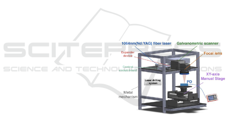
Figure 1 shows the experimental setup of the
scanning laser drilling system for the laser drilling of
multi-layer flexible printed circuit board. The system
composed of a pulsed Ytterbium fiber laser,
expander device, focal lens, galvanometric scanner
and XY-axis manual stage. The wavelength and
maximum power of the laser source are 1064 nm
and 30 W, respectively. The working distance of the
lens is 152.6 mm and the scanning range is 80 × 80
mm2. All optical and electronic components were
precisely positioned through the designed metal
mechanisms. The photodiode and power meter were
used to measure the average power of laser with
various parameters before conducting the drilling
process. The estimated value of spot size is about 81
μm, and the depth of field is about 4,256 μm. The
effective laser processing area could be directly
defined by the graph inputted into the software. A
laptop connected with the control circuit board was
used to interactively drive the laser to perform the
hole cutting of the samples.
Figure 1: Experimental setup of the laser drilling system.
Figure 2 shows the relationship between the
pulse frequency and relative peak power of the laser
source. The values of peak power were calculated by
dividing the pulse frequency and time duration from
measured average power. The various duty cycles
for laser driving are represented by the various color
curves. From the figure we can see that the
maximum peak powers of the laser occur at the
pulse frequency of 90 KHz. The peak power is
rapidly attenuated from 90 to 1000 KHz, and the
difference is small after 1000 KHz. Also, the light
intensity is relatively unstable at pulsed frequency
Laser Drilling of a 7-layer Flexible Printed Circuit Board using a Pulsed Ytterbium Fiber Laser System
179
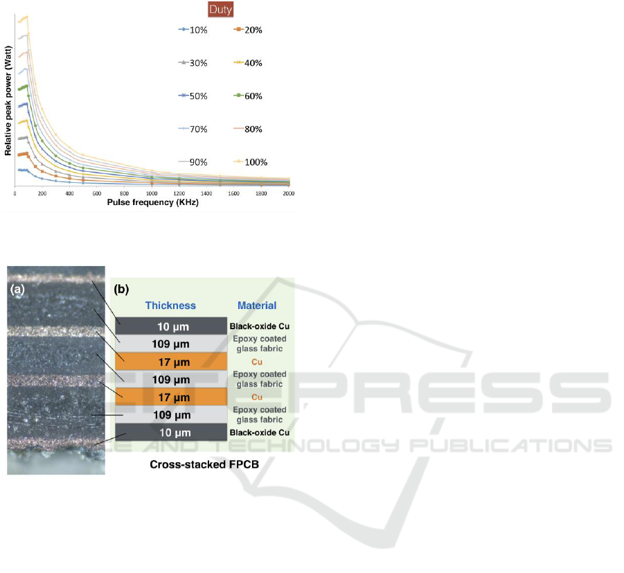
below 60 KHz. Therefore, the suitable parameters
for laser drilling are between 60 ~ 1000 KHz.
Figure 2: The relationship between the pulse frequency
and relative peak power of the laser source.
Figure 3: (a) The cross-sectional image and (b) Structural
diagram of the cross-stacked FPCB.
The sample for laser drilling was a FPCB cross-
stacked with black-oxide copper, copper and epoxy
coated glass fabric, as shown in figure 3. Figure 3(a)
is the cross-sectional image of the sample measured
by the optical microscopy. The thickness and the
material of the cross-stacked FPCB are shown in
figure 3 (b). The top and bottom layer are 10 μm
thick black-oxide copper. The dielectric layers are
109 μm thick epoxy coated glass fabrics. The inner
conductive layers between dielectric layers are 17
μm thick coppers. The cross section of the sample is
formed by the cutting of a diamond knife, therefore
the softer copper layer will be pulled and cause it to
look thicker in figure 3 (a). Also, the transverse
direction glass fabric can be seen at the bottom layer
of the dielectric layer. Before the laser processing,
the surface of the sample should be cleaned carefully
with alcohol. The particles on the sample surface can
lead to laser processing errors. As the sample is
softer, it is easy to warp and deformation. A mount
was made to effectively hold the sample and
maintain that the sample surface accurately located
on the focal plane of the laser. The stability of the
laser processing has been verified before the start of
the experiment.
3 RESULTS AND DISCUSSION
The parameters for laser drilling are very diverse,
including the duty cycle, pulse frequency, the
number of shots, the delay time and trepanning
speed, and so on. Each parameter will have an
impact on the machining process. Before starting
laser drilling, the laser focal plane must be
positioned on the surface of the FPCB to maximize
the efficiency of laser ablation. The adjustment of
the focal plane (z-axis) was achieved by the beam
expander in the system, rather than the use of a
mechanical movement stages. As the focal spot of
the laser is relatively small, so to achieve 100 μm
drilling must use the trepanning method. Before that,
we must first understand the relationship between
the size of the hole and the machining parameters
when the FPCB is directly drilled without
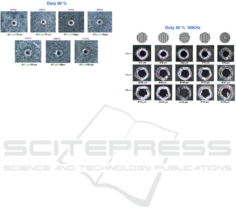
trepanning. Figure 4 shows the optical images of the
laser-drilled results. In order to achieve thru-holes,
the higher peak power of laser must be used. The
duty cycle of laser is 50%, the pulse frequency is 50-
110 KHz, and the number of shots is 1000 shots.
The green words indicate the aperture size of the
thru- hole, and the black words represent the surface
ranges of the FPCB affected by the heat damage.
Although the spot size of the laser is about 81um,
only the central part of the higher energy area can
effectively ablate the FPCB materials. It can be
found from Figure 3 that the laser processing energy
is highest at the frequency of 90 kHz. Corresponding
to Figure 4, the hole is relatively larger and the
diameter is about 41um. The farther the pulse
frequency from 90 KHz, the smaller the hole. It can
be estimated that the minimum thru-hole size drilled
by the system is about 20 μm. The processing
quality around the circumference of the hole also
needs to be concerned. If the heat damages are too
large, it will often cause the unpredictable problems
while the FPCB was used. After comparing the
contours of each hole, it could be found that the
better thru-hole which has balance ratio of inner and
outer diameter occur at the pulse frequency of 90
KHz. Although the smaller holes have better
PHOTOPTICS 2018 - 6th International Conference on Photonics, Optics and Laser Technology
180
resolution, the heat-affected regions did not
correspondingly become smaller.
Figure 4: Optical images of the holes by directly laser
ablation without trepanning.
In order to perform a 100 μm aperture laser
drilling, the trepanning procedure is required. The
correct trepanning method can effectively make the
hole size increase and maintain the circle shape. We
must first understand that whether the various
trepanning methods will have impact on the shape of
the hole. Figure 5 shows processing results using
five kinds of trepanning mode, including two-way,
one-way, lateral and vertical progressive scanning
and snail-like trepanning. In the software, the input
hole size images are 50 μm, 80 μm and 100 μm.
Because the actual drilled hole size is always greater
than the settings size, the input hole size images
should be less than 100 μm to achieve a just 100 μm
size hole. In order to achieve thru-hole, the higher
peak power of laser was used. The duty cycle of
laser is 80%, the pulse frequency is 90 KHz, and the
number of shots is 1000 shots. From the figure you
can see the holes are not perfect round. The reason is
that the surface of the black-oxide copper of the
FPCB is quite rough, and the glass fabric weaving in
dielectric layer is randomly distributed, so the
uniformity of laser processing cannot be perfect. In
figure 5, it could be found that the 50 μm hole size
image will form an actual hole with about 78 um
diameter, which is enlarged by 1.56 times. The 80
μm hole size image will form an actual hole with
about 100 μm diameter, which is enlarged by 1.25
times. That is also the hole size what we expect. The
100 μm hole size image will form an actual hole
with about 116 μm diameter, which is enlarged by
1.16 times. In other words, the larger the hole size
setting image will generate a hole which is closer to
the actual drilling hole size. This phenomenon may
come from the effect of the resolution of the laser
spot. In addition, the use of 50 μm hole size image
setting will generate a diamond-like shape. This
problem may come from the resolution limit of the
galvanometer mirrors. Therefore, using a larger hole
size image for laser drilling setting may easily
achieve a perfect round hole. However, the current
processing results only like a relatively round
pentagon.
Figure 5: Optical images of the holes drilled by various
trepanning modes and setting hole sizes.
Theoretically, the higher the peak power will be
easier to penetrate through the FPCB. But in fact it
needs to match the trepanning speed and other
conditions. In order to quickly understand the
drilling results with using various peak power and
pulse frequency, a laser-drilling array method was
used to quickly help us to find the appropriate range
of parameters. Figure 6(a) shows the array pattern
with various parameters for image setting in the
system. The trepanning mode is snail-like and the
hole size is 80 μm. The vertical axis is the pulse
frequency from 10 to 2000 KHz, and the horizontal
axis is the duty cycle from 10 to 100%. Figure 6(b)
shows the actual hole array after laser machining. In
order to confirm whether the parameters can achieve
the thru-holes, in uniform white light was used to
illuminate the sample from the back. As long as the
FPCB has been penetrated, a light spot would be
observed. It can be found that the higher pulse
frequency part will cause serious thermal effect
around the holes. The external qualities of the holes
are totally bad. The formation of thru-holes falls in
areas of high peak power. Some holes have
particularly large light spot may not because the hole
size is larger. Because the sidewalls of the hole have
less scattering impurities (such as glass fabric
residues) will also increase the amount of
transmission light. The actual hole still needs a high
magnification microscope to directly observe and
qualify.
Laser Drilling of a 7-layer Flexible Printed Circuit Board using a Pulsed Ytterbium Fiber Laser System
181
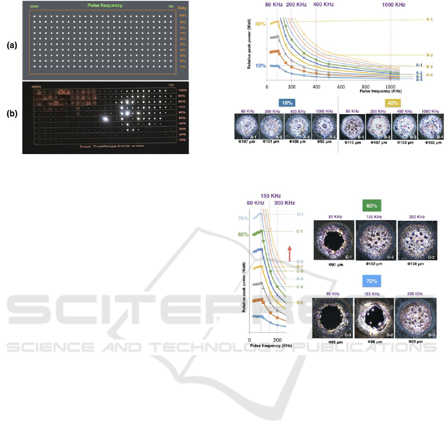
Figure 6: Set pattern and actual hole array after laser
machining with various duty cycle and pulse frequency.
After selecting the hole size image of 80 μm for
setting, an actual hole size of about 100 μm can be
successfully formed. It is necessary to understand
the processing parameters that can form a thru-hole
or blind-hole, and whether the holes size will change
correspondingly after drilling. Figure 7 shows the
laser drilling results of FPCB using the previously
optimized parameters: snail trepanning with 80 μm
hole size image setting. The variables are the laser
duty cycle and pulse frequency. In order to easily
observe the actual peak power difference of the
laser, figure 3 is narrowed down and embedded to
the top of the Figure 7. The corresponding pulse
frequencies are marked by dotted lines. The actual
peak powers of the laser with 10% duty cycle are
labeled as A-1, A-2, A-3 and A-4 at pulse frequency
of 80, 200, 400 and 1000 kHz. The actual peak
powers of the laser with 40% duty cycle are labeled
as B-1, B-2, B-3 and B-4 at pulse frequency of 80,
200, 400 and 1000 kHz. The results show that the
drilled hole size can be controlled in the vicinity of
100 μm regardless of the value of the laser duty
cycle and pulse frequency. Due to the uncertainty of
the measurement and the non-uniformity of the
FPCB material, the deviation of about 10 μm should
be accepted. The peak power below the B-1 level
can ablated the surface of the black-oxide copper of
the FPCB, However, it cannot effectively achieve
broken copper of the first layer. Due to the effect of
the snail trepanning, the edge of the hole will have a
dark ring. It indicates that the areas were ablated
slightly. Although A-1 and B-3, A-2 and B-4 have
similar peak power, however the qualities of the
holes are totally different. The reason is that the
different pulse frequencies would cause different
drilling overlapping under a fixed trepanning speed.
Figure 7: Laser drilling results using 10% and 40% duty
cycle at pulse frequency of 80, 200, 400 and 1000 kHz.
Figure 8: Laser drilling results using 60% and 70% duty
cycle at pulse frequency of 80, 150 and 200 kHz.
Under the same drilling parameters, figure 8
shows the drilling results with higher duty cycle.
Since the pulse frequency above 400 KHz cannot
provide an enough peak power for thru-hole
generation, the pulse frequency parameters are
changed to be 80, 150, 200 kHz. The duty cycles are
raised to be 60% and 70%. Figure 3 is narrowed
down and embedded to the left of the Figure 7 and
the corresponding pulse frequencies are also marked
by dotted lines. The actual peak powers of the laser
with 60% duty cycle are labeled as C-1, C-2 and C-3
at pulse frequency of 80, 150, 200 KHz. The actual
peak powers of the laser with 70% duty cycle are
labeled as D-1, D-2 and D-3 at pulse frequency of
80, 150, 200 KHz. The results still demonstrate that
the drilled hole size can be controlled in the vicinity
of 100 μm regardless of the value of the laser duty
cycle and pulse frequency. With the validation of
microscopic images and backlighting observation,
100 μm thru-hole will generate when the laser peak
PHOTOPTICS 2018 - 6th International Conference on Photonics, Optics and Laser Technology
182
power is higher than D-2 (red arrow). A lot of tiny
pores were gradually formed on the hole surface if
the laser peak power is between B-1 and C-3. The
depths of these holes are about 1 to 2 μm only. It
means that only the surface of the black-oxide
copper is ablated away. The result also indicates that
using the laser with peak power higher than D-2
level and reducing the number of shots could
achieve the various blind holes. The laser with peak
power lower than B-1 cannot form the blind holes
even if the number of laser shots is increased.
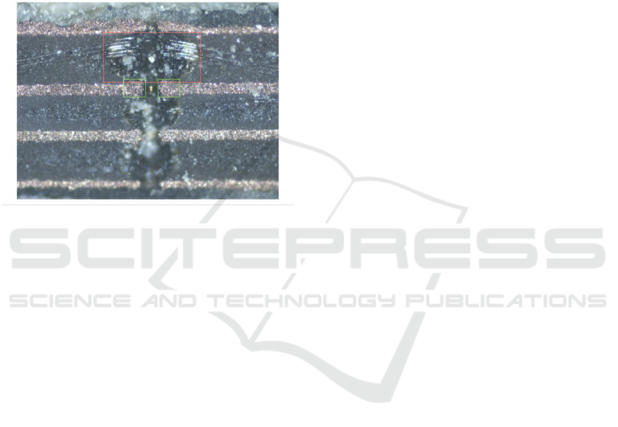
Figure 9: The cross-sectional image of the drilled thru-
hole measured by an optical microscope.
Figure 9 shows the cross-sectional image of the
drilled thru-hole measured by the optical
microscope. The laser drilling parameters are: duty
cycle of laser is 80%, the pulse frequency is 90 KHz,
and the hole size image for setting is 80 μm. By
optical alignment using a digital microscope, the
diamond round knife can be precisely positioned on
the hole middle for cutting the hole in half. As the
mechanical cutting will pull copper layer, it will
cause hole shrinking in metal layers, as shown in the
green square area. Although the use of grinding
method can achieve a smoother cross-section of
FPCB, the time cost and failure rate are too high.
Figure 9 shows that the laser-drilled thru-hole has a
shape like a calabash. Because of the trepanning
processing, a lot of shots and the focal plane of laser
located on the surface of the FPCB, the heat will
concentrate on the first and second layer around the
hole region. The copper has better thermal
conductivity, therefore the glass fabric layer will
occur expanded ablation, as shown in the red square
area. The laser-drilled hole can be control as a 100
um size, however, the exit need to rapidly discharge
the scraps. The hole at the other side will burst and
form a larger hole. The size is about 1.6 to 2 times of
original hole. We believe that the quality of hole
sidewall can be further improved by turning the
better processing parameters. A better way should be
a gradual trepanning down process that can maintain
the hole size even in the different depth. For further
experiments, we will work in this direction.
4 CONCLUSIONS
This study succeeded in developing a simple, rapid
and relative accurate method for the quality analysis
of the laser-drilled hole on flexible printed circuit.
An laser drilling system system equipped with 1064
nm pulsed Ytterbium fiber laser, optical expander,
galvanometric scanner and XY-axis motorized stage
was used to perform the hole cutting with many
kinds of processing parameters. With the optical
observation of experimental results, the size and
shape of each laser-drilled holes would exhibit their
individual characteristics. Both the through and
blind holes can be successfully formed. Following
the numerical analysis, the amendment to the laser
drilling process could be proposed to achieve a ideal
hole shape, minimal carbonization and thermal
influence. This system is compatible with most
laser-drilling experiment and can be used for multi-
layer FPC. This study provides a useful database for
FPCB drilling technology.
ACKNOWLEDGEMENTS
The authors would like to express their appreciation
for financial aid from the Ministry of Science and
Technology, R.O.C under grant numbers MOST
105-2622-E-492-029-CC3. The authors would also
like to express their gratitude to the Instrument
Technology Research Center of National Applied
Research Laboratories for the support.
REFERENCES
Malcolm C. Gower, 2000. “Industrial applications of laser
micromachining”, Optics express, 7(2), 56.
Winco K.C Yung, J.S Liu, H.C Man, T.M Yue, 2000.
“355 nm Nd:YAG laser ablation of polyimide and its
thermal effect”, Journal of Materials Processing
Technology, 101(1-3), 306.
Han-Chao C., Yu-Hsuan L., Kuo-Cheng H., 2015. ”
Accurate laser skin perforation technique aimed at
promoting bleeding and reducing pain” Journal of
Innovative Optical Health Sciences, 8(6), 1550029-1-
8.
Laser Drilling of a 7-layer Flexible Printed Circuit Board using a Pulsed Ytterbium Fiber Laser System
183

Surmann, H., Nuechter, A., and Hertzberg, J., 2003. "An
autonomous mobile robot with a 3d laser range finder
for 3d exploration and digitalization of indoor
environments," Robotics and Autonomous Systems,
vol.45, no.3-4, 181-198.
Seokbae, S., Hyunpung, P., Kwan, H. L., 2002.
“Automated laser scanning system for reverse
engineering and inspection”, International Journal of
Machine Tools and Manufacture, 42(8), 889-897.
Ching-Ching, Y., Yi-Cheng, L., Chih-Chung, Y., Yu-
Hsuan, L., Kuo-Cheng, H., Keh-moh, L., Wen-Tse H.,
2017. “Laser-induced coloring of titanium alloy using
ultraviolet nanosecond pulses scanning technology”,
Journal of Alloys and Compounds, 715(25), 349-361.
Hsin-Yi, T., Chih-Chung, Y., Wen-Tse, H., Kuo-Cheng,
H., 2016. “Analysis of fabric materials cut using
ultraviolet laser ablation”, App. Phy. Mat. Sc. Process.,
10.1007/s00339-016-9815-2.
Kestenbaum, A., D'Amico, J. F., Blumenstock, B. J.,
DeAngelo, M. A., 1990. “Laser drilling of microvias
in epoxy-glass printed circuit boards”, IEEE
Transactions on Components, Hybrids, and
Manufacturing Technology, 13(4), 1055-1062.
Avanish, K. D., Vinod, Y., 2008. “Laser beam
machining—A review”, International Journal of
Machine Tools and Manufacture, 48(6), 609-628.
Winco, K. C. Y., Jun, W., T. M. Y., B. L. Z., C. P. Lee.,
2007, “Nd:YAG laser drilling in epoxy resin/AlN
composites material”, Composites Part A: Applied
Science and Manufacturing, 38(9), 2055-2064.
Reinhart, P., Wolfgang, S., Robert, S., 2010.
“Hydrodynamics of material removal by melt
expulsion: Perspectives of laser cutting and drilling”,
Physics Procedia, 5(A), 1-18.
Owen, M., E. Roelants, and J. Van P., 1998. "Laser
drilling of blind holes in FR4/glass." Circuit
World, 24(1), 45-49.
PHOTOPTICS 2018 - 6th International Conference on Photonics, Optics and Laser Technology
184
