
Wearable RGB Camera-based Navigation System for the Visually
Impaired
Reham Abobeah
1
, Mohamed Hussein
2,3
, Moataz Abdelwahab
4
and Amin Shoukry
1,3
1
CSE Department, Egypt-Japan University of Science and Technology, New Borg El-Arab City, Alexandria, Egypt
2
Information Sciences Institute, Arlington, Virginia, U.S.A.
3
CSE Department, Faculty of Engineering, Alexandria University, Alexandria, Alexandria, Egypt
4
ECE Department, Egypt-Japan University of Science and Technology, New Borg El-Arab City, Alexandria, Egypt
Keywords:
Mono Camera, Temporal Alignment, Blind Navigation, Indoor/ Outdoor Navigation, Pose Estimation,
Deviation Detection, Path Following.
Abstract:
This paper proposes a wearable RGB camera-based system for sightless people through which they can easily
and independently navigate their surrounding environment. The system uses a single head or chest mounted
RGB camera to capture the visual information from the current user’s path, and an auditory system to inform
the user about the right direction to follow. This information is obtained through a novel alignment technique
which takes as input a visual snippet from the current user’s path and responds with the corresponding location
on the training path. Then, assuming that the wearable camera pose reflects the user’s pose, the system corrects
the current user’s pose to align with the corresponding pose in the training location. As a result, the user
receives periodically an acoustic instruction to assist him in reaching his destination safely. The experiments
conducted to test the system, in various collected indoor and outdoor paths, have shown that it satisfies its
design specifications in terms of correctly generating the instructions for guiding the visually impaired along
these paths, in addition to its ability to detect and correct deviations from the predefined paths.
1 INTRODUCTION
The World Health Organization (WHO) provided an
estimate of the number of visually impaired people
around the world in 2014 to about 285 million. This
estimate was further split into around 246 million
with low vision and 39 million with a total loss of
sight. Among blind people, long canes and guide
dogs are considered the most widespread naviga-
tion aids (Manduchi and Kurniawan, 2011). However,
they have a small coverage range and do not pro-
vide a clear directional information toward the des-
tination. Recently, computer vision technology has
been considered as an effective and cheap alternative
for blind assistance, in navigation and way finding.
However, most of the existing systems are inaccessi-
ble to all individuals either due to their design com-
plexity or high computation cost. As a result, they
need much more training efforts from the blind users
before adopting them. Also, as they mainly depend on
multiple sensors for capturing data from surrounding
environment, the decisions based on these data may
be not guaranteed and the blind person relies on his
estimation for the safe path. In addition, the major-
ity of these systems are either applicable for indoor or
outdoor environments due to their different natures.
In this paper, we introduce a new mono RGB
camera-based navigation system for the majority of
the blind people. The system assists the blind individ-
uals to independently navigate their routine paths till
they reach safely to their destinations. It also alarms
the users in case any deviation from the predefined
paths is detected and informs them with the correct
direction to follow within a reasonable time. By the
end, The system is evaluated through testing on a var-
ious collected indoor and outdoor routine paths with
the help of a number of volunteers.
The rest of this paper is organized as follows:
Section 2 reviews the existing vision-based naviga-
tion systems for the blind people and the video align-
ment techniques. Section 3 introduces an overview
of the different system’s components, in addition to
a detailed description of the software modules. The
proposed system is evaluated and the results are dis-
cussed in Section 4. Finally, conclusion and future
work are given in Section 5.
Abobeah, R., Hussein, M., Abdelwahab, M. and Shoukry, A.
Wearable RGB Camera-based Navigation System for the Visually Impaired.
DOI: 10.5220/0006617505550562
In Proceedings of the 13th International Joint Conference on Computer Vision, Imaging and Computer Graphics Theory and Applications (VISIGRAPP 2018) - Volume 5: VISAPP, pages
555-562
ISBN: 978-989-758-290-5
Copyright © 2018 by SCITEPRESS – Science and Technology Publications, Lda. All rights reserved
555

2 RELATED WORKS
2.1 Video Alignment
The aim of video alignment is to find the correspond-
ing frames in two given videos, called the reference
and the observed video, respectively. Unlike image
alignment techniques, space and time must be consid-
ered in case of aligning two sequences. Specifically,
synchronization or temporal alignment refers to map-
ping each frame in the observed video to its most sim-
ilar corresponding frame in the reference sequence
(Diego et al., 2011). Video alignment is a common
problem in many computer vision applications such
as video editing (Wang et al., 2014), change detection
(Diego et al., 2011), action recognition (Ukrainitz and
Irani, 2006), and abandoned objects detection (Kong
et al., 2010). In this work, the video alignment appli-
cations are extended to include real time navigation of
blind individuals.
Most of the previous video alignment methods
rely on stationary or rigidly connected cameras. Be-
sides, they suppose that the trajectories of moving
points along the video are known (Padua et al., 2010;
Wolf and Zomet, 2006) or the existence of some linear
relationship between the two corresponding videos
(Tresadern and Reid, 2009; Ravichandran and Vidal,
2011; Padua et al., 2010). Our work considers a more
complex video alignment problem. Specifically, our
scenario is to synchronize two videos which are ac-
quired from two independently moving cameras fol-
lowing the same path such that an overlapping field of
view exists among the two videos.
2.2 Navigation Systems
Electronic travel-aid (ETA) systems have been intro-
duced to provide the blind person with a more com-
fortable and independent mobility style than the tra-
ditional aids like white cane and guide dog. They
can be categorized according to how they sense the
surrounding environment and the modality through
which they communicate with the disabled person.
Sensing the environment can be through laser (Yuan
and Manduchi, 2005), ultrasound (Laurent and Chris-
tian, 2007), or vision sensors, while communication
with the user can be either through an auditory or tac-
tile interface. Although, the majority of ETA systems
were designed to replace or enhance the functionality
of the white cane, they cannot avoid the user’s head
level-obstacles in many situations.
Recently, many researchers are focusing on using
computer vision techniques as a less costly and more
effective solution for blind people assistance in their
real navigation. All works in this area can be classi-
fied along three directions: the stereo, RGB-D, and
RGB camera-based navigation systems. Stereo based
systems (Saez et al., 2005; Martinez and Ruiz, 2008;
S
´
aez and Escolano, 2011), estimate a user’s motion
by considering the camera trajectory. They also ex-
ploit the visual and depth information acquired by
the stereo sensors to build a 3D map of the user’s
surroundings for successful path planning or obsta-
cle detection. As these systems are either chest or
shoulder mounted, they may need the body rotation
for scanning the user’s surrounding environment. In
2010, Pradeep et al. have introduced the first real time
head mounted stereo-based navigation system for the
visually impaired (Pradeep et al., 2010). The head
mounted style provides its user with a more com-
fortable way to traverse his surroundings, whereas
the wearable tactile vest interface keeps him away
from the obstacles. Although most of the stereo-based
travel-aid systems have been proved to be effective
in certain environments, they suffer from some short-
comings. First, they do not perform well in environ-
ments with low textures like white walls. Also, they
provide the sightless individual with an estimation of
the safe path due to the quantized depth information
acquired from the stereo sensors. In addition, they re-
quire an excessive computational costs for construct-
ing the depth maps for a successful navigation, espe-
cially in cluttered environments.
Compared to the stereo-based systems, single
camera-based systems are more compact and easier
to maintain. In this respect, Lee and Medioni used the
RGB-D camera as an alternative to the stereo in (Lee
and Medioni, 2011; Lee and Medioni, 2014) and pro-
posed a real time navigation system for the blind peo-
ple. The system enabled the sightless people to detect
obstacles in indoor environments with a wider range
of detection than of white canes or stereo-based sys-
tems. Recently, in 2016, another RGB-D-based sys-
tem (Aladren et al., 2016) has been proposed. The au-
thors exploited the combination of the depth informa-
tion and the image intensities for extending the range
of depth information aiming at detecting far obstacles.
In addition, the system enables the blind person to
safely navigate the challenging and unknown indoor
paths. Concurrently, Lee and Medioni introduced an-
other complete real time system for the blind individ-
uals navigation (Lee and Medioni, 2016). The sys-
tem estimates the shortest safe path to the user’s des-
tination through generating the appropriate real time
maps for his surrounding environment. The blind user
defines his current and goal location to the system
via some mobile interface. Then, the system responds
with an appropriate cue which alerts the user through
VISAPP 2018 - International Conference on Computer Vision Theory and Applications
556
a tactile system toward the generated safe path. In
contrast to the stereo-based navigation systems, the
majority of RGB-D -based systems achieve accurate
results in case of indoor environments even for those
with low textures. Besides, they require less process-
ing time for generating the depth maps. However, they
are not applicable to the outdoor environments.
As an extension to a mono camera-based systems,
RGB cameras have been adopted for assisting the
visually impaired in navigation instead of stereo or
RGB-D cameras. In 2008, an RGB camera-based in-
door deviation detection system has been proposed
for the blind users (Pathangay, 2008). The system
maps, at run time, the captured input from the cur-
rent user’s scene to its corresponding scene in a pre-
defined path, using the dynamic time warping algo-
rithm. Then, the path deviation can be detected when
the similarity score average in a defined detection
window is below some defined threshold. However,
this method suffers from some defects. First, it of-
ten detects the deviations among various indoor paths
with a high delay that reaches up to hundred frames.
Also, it can not provide the user with a corrected di-
rection to follow in case of deviation detection. More-
over, it falsely alarms the user about the existence of
deviation in the current path with a high rate, as a lit-
tle change in camera’s pose may cause a higher ratio
of dissimilarity. Recently, an Android navigation ap-
plication was introduced for the sightless individuals
depending on the smart phone’s camera (Idrees et al.,
2015). It starts by defining the current user’s location
through scanning one of the existing QR codes on the
floor along the indoor path. Consequently, it gener-
ates the shortest and optimal path toward the user’s
destination. In addition, it can detect and correct the
user’s deviation from the predefined path. Unfortu-
nately, the system is not practical for outdoor paths
as it needs to cover the whole path’s width by hori-
zontal tapes of QR codes to avoid the scanning prob-
lem. More recently, a new smart phone-based system
has been introduced for assisting the sightless people
to find their way to their destinations in unknown in-
door environments (Ko and Kim, 2017). Upon defin-
ing the target destination, the system starts by clas-
sifying the type of current user’s place. Accordingly,
it begins by localizing the QR code which exists at
a specific location based on the place type and then
fetching the code information which may be either lo-
cation or directional code. After that, the system pro-
vides the user wsome guidance instructions via a text
to speech service. In addition, it enables the user to go
back to his starting location after reaching the desti-
nation through storing its trajectory to the destination,
with the aid of some inertial sensors in the phone.
In this paper, we propose a new navigation sys-
tem targeting the majority of blind people. It depends
only on the appearance information from the user’s
environment captured through a mono RGB camera
sensor to help the blind user to reach safely to his des-
tination. Also, without additional sensors, the system
can operate in both indoor and outdoor environments.
3 SYSTEM DESCRIPTION
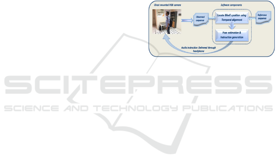
In this section, we introduce an overview of the dif-
ferent hardware and software components of the pro-
posed system, as shown in Figure 1.
Figure 1: Overview of the proposed navigation system.
3.1 Hardware Components
The system is composed of three main components:
a chest/head mounted camera, a laptop kept in the
blind’s knapsack, and a wearable headphone. The
wearable camera acquires a snippet from the current
blind’s path to be processed by the navigation system.
Then, the system generates an audio instruction and
delivers to the blind user via a simple wearable head-
phone, in order to guide him toward the destination.
3.2 Software Components
The proposed system consists of two major modules:
(i) the temporal alignment module which is responsi-
ble for locating the current blind’s position w.r.t to a
training video. (ii) the pose estimation and instruction
generation module which generates an audio instruc-
tion for the user to follow to remain consistent with
his pose at the same location in the training video.
3.2.1 The Temporal Alignment Module
In contrast to the proposed alignment technique which
relies on a moving camera, most of the prior video
alignment techniques depend on stationary or rigidly
connected cameras. We also suppose that the ob-
served video is contained in the reference video. As
a result of applying the proposed technique, each
Wearable RGB Camera-based Navigation System for the Visually Impaired
557

frame from the input sequence is mapped to the one
with the maximum similarity score in the reference
sequence. More specifically, upon capturing a small
snippet from the current scene in some path, the blind
individual’s location is defined in the corresponding
training video using the proposed technique.
Consider two sequences F
O
m
and F
R
n
where F
O
m
represents the observed video with length M, m=
[1...M] and F
R
n
represents the reference video with
length N, n= [1...N]. The issue is to find the mapping
among these two videos.
In our work, we propose a new dynamic program-
ming formulation for solving the alignment problem
which is considered the main step for our navigation
system. Practically, consider that i refers to a spe-
cific frame in the observed sequence and j its corre-
sponding frame in the reference sequence. For obtain-
ing an accurate mapping between these two frames,
the history of the previous frames’ mapping till the
current observed frame is considered, as indicated in
Eq.(1). Also, as our system is designed for online op-
eration and needs to make a decision with each ob-
served frame, so the observed frame should be in-
cluded in the calculations of finding its corresponding
frame, as shown in Eq.(2).
MS(i, j) = max
MS(i − 1, j − 1) + Sim(i, j)
MS(i − 1, j)
MS(i, j − 1)
(1)
MS
last
(i, j) = max
(
MS(i − 1, j − 1) + Sim(i, j)
MS
last
(i, j − 1)
(2)
Where Sim(i, j) represents the similarity score be-
tween the i
th
and j
th
frames.
Regarding the calculation of the similarity mea-
sure, we rely on the spatial pyramid matching tech-
nique introduced in (Lazebnik et al., 2006). It is an
effective technique for image representation and is
proved to be better than other existing image descrip-
tors like SIFT and gist. This technique works by con-
sidering the image at different levels l = 0, 1, ..., L−1,
where l represents a specific image’s level. Each level
is partitioned into a number of sub grids such that the
total number of grids in that level is D = 2
l
. Specifi-
cally, we want to provide a score representing to what
extent frames i and j are similar using the spatial pyra-
mid technique. Firstly, the total number of matching
among the two frames at a specific level is found by
calculating the gray-scale histogram intersection be-
tween each corresponding sub-grid, using Eq.(3).
I
l
=
D
∑
d=1
min(H
l
i
(d), H
l
j
(d))
(3)
Where H
l
i
(d) and H
l
j
(d) represent the histograms
of the two corresponding sub-grids, d, for the two
frames at a specific level l, respectively.
Then, the pyramid match kernel which is the sum
of the weighted histogram intersections for all levels
of the two intended frames is obtained using Eq.(4).
Clearly, each level is weighted inversely proportional
to the wideness of its cells,
1
2
L−l
, aiming at giving
more penalty to the matching occurring at wider cells.
K
L
(i, j) =
1
2
L
I
0
+
L
∑
l=1
1
2
L−l−1
I
l
(4)
After that, in order to obtain the final spatial ker-
nel which represents the similarity score among i, j
frames, we consider the different features which com-
pletely represent the image. Specifically, each compo-
nent in the pyramid kernel, given in Eq.(4), represents
a separate kernel for one feature, and the spatial ker-
nel is the sum of all separate kernels, as follows in
Eq.(5):
Sim
score
(i, j) = K
L
(i, j) =
T
∑
t=1
K
L
(i
t
, j
t
)
(5)
Where K
L
(i
t
, j
t
) is the kernel of feature type t, and T
is the total number of the different image features.
3.2.2 Pose Estimation and Instruction
Generation
This step is responsible for extracting the right in-
structions for the blind person during his navigation
along the path, according to a predefined path. In or-
der to estimate these instructions, we consider that
the current pose of the wearable camera provides an
estimate of the current user’s pose. Once the system
defines the user’s location w.r.t a training path using
the proposed alignment technique, it starts to estimate
his pose at that defined location. This is estimated as
the relative camera pose between the training frame
which reflects the user’s location and the frame fol-
lowing it by a time duration sufficient to reflect the
right pose. Experimentally, this duration is found to
be two seconds for the outdoor path and half a second
for an indoor path.
The pose estimation process depends mainly
on the matching process between two frames and
using some similarity measure. We have chosen
the Speeded Up Robust Features (SURF) technique
which is invariant to both scale and rotation during
the interest points detection and feature vectors ex-
traction (Bay et al., 2008). In order to estimate the
best model that fits most of the space points, i.e. main-
tain only the inliers or the true matches, and exclude
the outliers, the best choice is the Random sample
VISAPP 2018 - International Conference on Computer Vision Theory and Applications
558
Consensus (RANSAC) algorithm (Fisher, 2002). But,
in our problem, we use the optimal RANSAC algo-
rithm (Hast et al., 2013), which outperforms the tradi-
tional algorithm for the following reasons. It performs
well in finding the optimal inliers’ set, even when
the percentage of inliers’ number is as low as 5%
of the total matches. Unlike the traditional RANSAC
which requires this percentage to exceed 50% for best
results. In addition, it returns the optimal set each
time with a slight difference whatever the number of
runs, especially with aerial images. However, it fol-
lows the standard RANSAC in case of multiple plane-
images. Finally, through using both the inliers, the es-
timated model, and the camera parameters, the cur-
rent pose for the blind user is estimated. Experimen-
tally, through using shots with various camera poses
for the same scene, we determine the suitable range of
angles for each individual’s pose which are expressed
by one of five meaningful directions, go straight, take
right, take left, slightly right, and slightly left. By the
end, our proposed system enables the blind individ-
ual to safely navigate along indoor and outdoor paths
without any human aid or extra sensors, through pe-
riodically providing him with an assistive instruction
within a reasonable time.
4 EXPERIMENTS AND RESULTS
4.1 Dataset Collection
Our dataset is collected such that it contains vari-
ous pairs of indoor and outdoor paths with different
lengths, six pairs for each. All outdoor paths are cap-
tured at our campus, under various illumination con-
ditions and with different start and end points. While,
the first four pairs of the indoor paths are recorded
at our cyber-physical systems lab, starting from the
same point, but with different destinations: white-
board, printer, door, and the meeting room, respec-
tively. And the last two are captured at an apartment
to add some variety to our dataset.
4.2 Experiments
The proposed system is tested using the HTC De-
sire 820 G PLUS dual sim-chest-mounted-camera
with 13 megapixels, (720x1280) resolution, and
(1080p@30fps) video camera. It runs on a machine
with the following configurations: CPU: Intel(R)
Core(TM) i7-4700 MQ @ 2.40 GHz, RAM: 8.00 GB,
and OS: Windows 10- 64 bit.
The performance of the system depends mainly on
the output of the proposed alignment technique intro-
duced in section 3.2.1. In other words, the more ac-
curate the blind’s location is determined by the align-
ment technique, the more successful is the estimation
of the user’s pose, and the more probable the correct
guiding instruction is generated. The first experiment
tests the alignment technique’s ability in determining
the correct user’s location in both indoor and outdoor
training sequences, respectively. In the second and
third experiments, the system’s accuracy is evaluated
regarding releasing the correct real time instructions
for the blind user as well as detecting and correcting
the user’s deviation from the predefined paths, respec-
tively. For more implementation details.
1
4.2.1 Experiment 1
This experiment tests the proposed alignment tech-
nique in defining the current user’s location. Given an
observed sequence from the user’s surroundings, our
technique proves its efficiency in mapping each ob-
served frame to its corresponding one in the reference
sequence in case of indoor and outdoor environments,
as shown in Figures 2, 3, respectively.
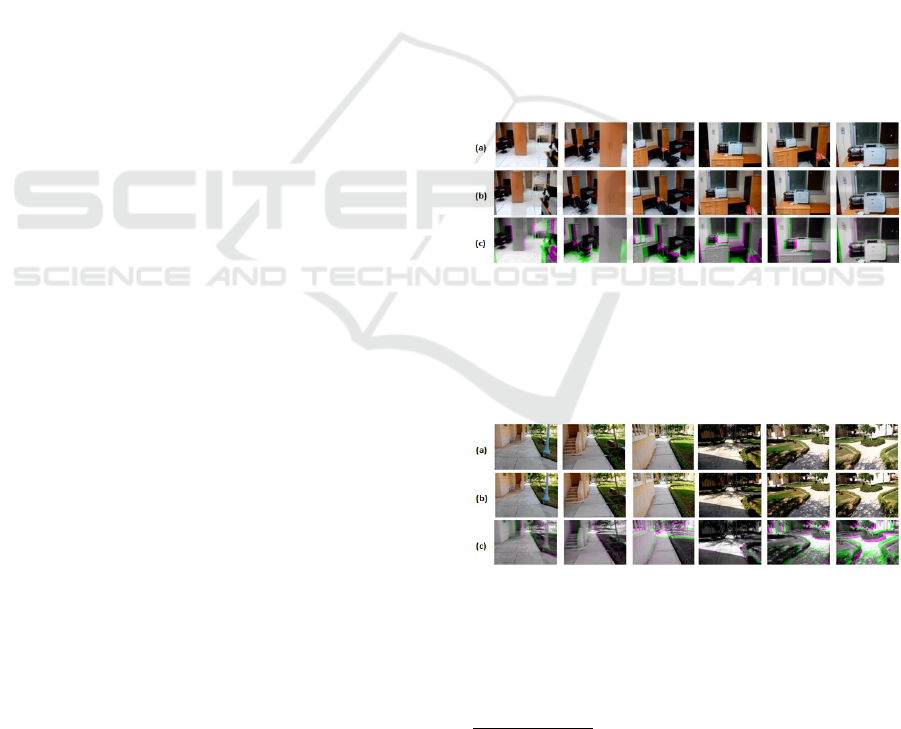
Figure 2: Example for Indoor Alignment. (a) Selected
frames from the observed video. (b) The corresponding
frames retrieved from the reference video (after temporal
alignment). (c) Fusion Image (Red and Blue channels of
color image are assigned to the observed frame, while the
Green channel is assigned to the reference frame).
Figure 3: Example for Outdoor Alignment. (a) Selected
frames from the observed video. (b) The corresponding
frames retrieved from the reference video (After temporal
alignment). (c) Fusion Image (as in Figure 2).
1
All experiments are implemented in MATLAB, using
Computer Vision Toolbox and re-sized images (80x60).
Also, all videos are sampled such that three frames per five
are selected in training videos while three frames per ten in
testing videos, for speeding up the alignment step.
Wearable RGB Camera-based Navigation System for the Visually Impaired
559
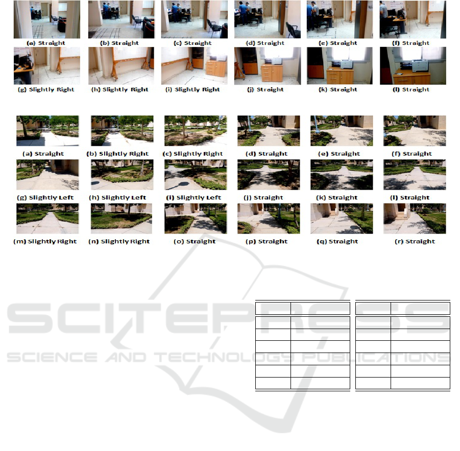
Figure 4: Example for Indoor Path instruction generation.
Figure 5: Example for Outdoor Path instruction generation.
4.2.2 Experiment 2
This experiment evaluates the system’s ability to gen-
erate the right instruction for the blind user every spe-
cific period of time, which amounts to one second,
according to a predefined path. For this task, we con-
struct a voting system for each path in the dataset with
the help of a group of seven individuals. This voting
system reflects the instruction that should be taken
at each selected frame from the real path accord-
ing to the majority of the individuals’ opinion. Then,
the generated instructions from our system are com-
pared with these reference instructions for the same
path and the system’s accuracy is calculated. Table 1
presents the system’s accuracy in generating the cor-
rect instructions during navigating various indoor and
outdoor routine paths.
Regarding the results of Table 1a, the system
achieves a high accuracy in most of the dataset paths.
However, the main reason behind the accuracy drop
in some outdoor paths is either the scene occlusion or
the high illumination variance between training and
testing sequences. As these reasons may cause failure
in generating the guidance instructions at some posi-
tions in these paths, our system provides the user with
stop instructions to avoid any troubles. Also, as the
system generates periodically, every one second, an
instruction, so in most cases this failure does not last
along the whole path and the system recovers quickly
its normal state in generating the assistive instructions
for the blind user. Although our system can efficiently
handle the small changes in the camera pose resulting
Table 1: System’s Accuracy in generating instructions.
(a) Outdoor
Path Accuracy%
Path1 97.06%
Path2 95.45%
Path3 97.92%
Path4 97.37%
Path5 93.55%
Path6 97.73%
(b) Indoor
Path Accuracy%
Path1 100%
Path2 100%
Path3 95%
Path4 100%
Path5 95.45%
Path6 100%
from the normal movements of the user, unstable and
sudden movements which may cause big changes in
the camera pose are unacceptable and make the sys-
tem fail to understand the surrounding environment.
This problem is considered as the common cause of
the slight reduction in some paths’ accuracy which
may result in a partial failure of the system to gener-
ate correct instructions in some positions along either
outdoor/ indoor paths, as shown in Table 1.
For more explanation, Figures 4 and 5 demon-
strate the generated instructions for the sightless indi-
vidual along some parts of path2 and path6 from the
indoor and outdoor paths in the dataset, respectively.
4.2.3 Experiment 3
This experiment measures the system’s accuracy in
detecting the user’s deviation from a predefined path,
within two scenarios: 1) The training and testing
videos describe the same path. 2) The training and
VISAPP 2018 - International Conference on Computer Vision Theory and Applications
560
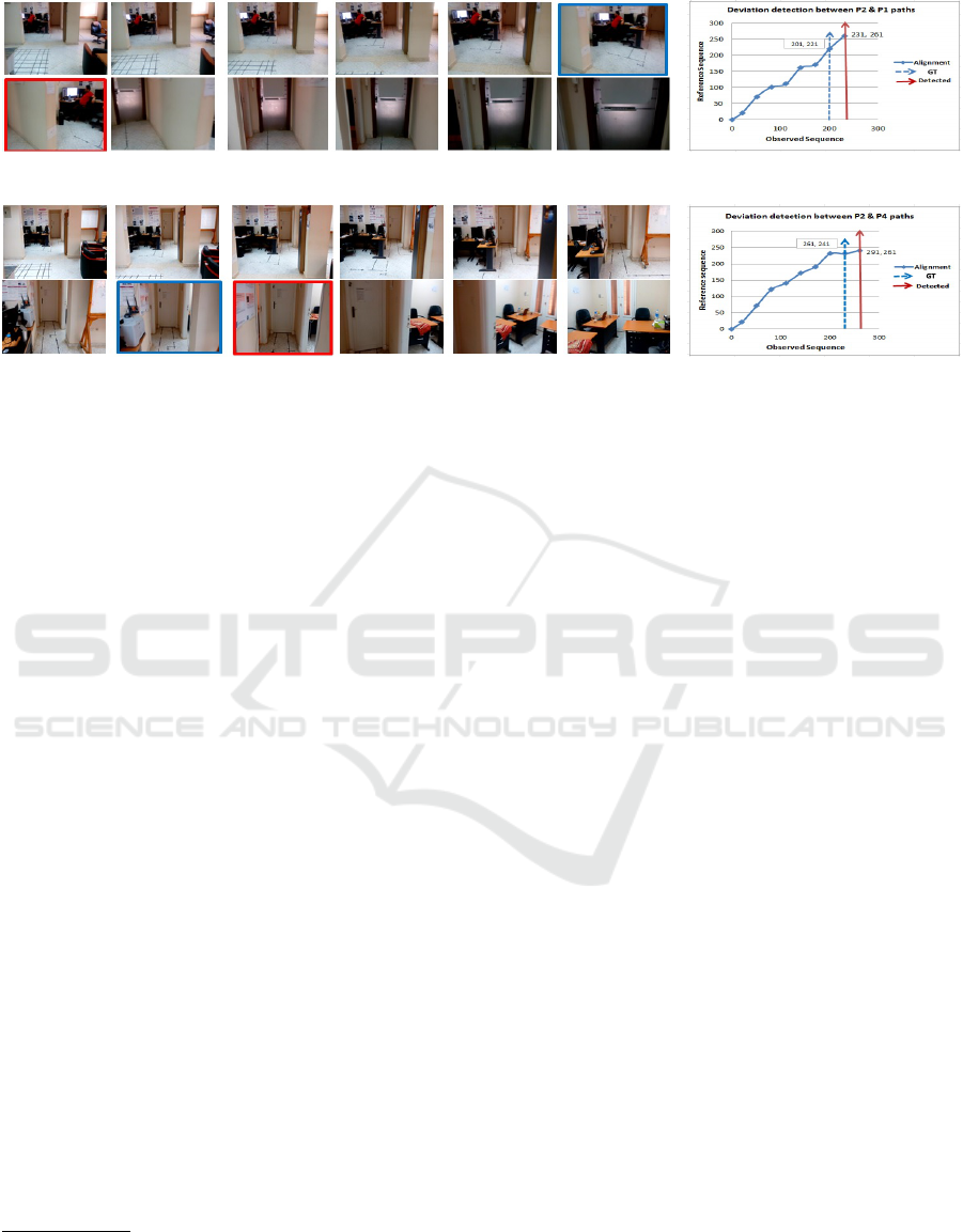
(a) Deviation detection between path P2 & P1 (b)
(c) Deviation detection between path P2& P4 (d)
Figure 6: (a,b) Two examples for Indoor Deviation Detection between path2, in Figure 4, and both path1 & path4, where Blue
and Red squares represent the ground truth and system detection, respectively. Two graphs (b,d) show the system’s delay in
detecting deviation between these paths.
testing videos describe two different paths. Regarding
the first scenario, it measures the system’s accuracy in
providing the user with a false alarm-deviation detec-
tion. While the second scenario measures the accu-
racy of the system in detecting the user’s deviation as
a true alarm. To achieve this experiment, we build the
ground truth by asking five individuals to mark when
the deviation starts to occur by applying the second
scenario in all dataset paths.
2
For the first scenario, the system results in no de-
viation detection, leading to an accuracy of 100%.
In other words, the proposed system does not suffer
from generating false alarm decisions. On the other
hand, the second scenario results in detecting the
existing deviations between all various paths in the
dataset, with an accuracy of 85.8%. In addition, the
delay taken by the system to detect a path deviation
is one second on average, as shown in Figures 6b
and 6d. This performance is better than that given in
(Pathangay, 2008), which detects the deviation with a
delay of the order of a hundred frames, i.e. ranging
from three to four seconds. It is worthy to mention
that, the proposed system achieves the same deviation
detection accuracy, even with small similarity score
thresholds, like 0.2 and 0.3.
2
The similarity score threshold is set to 0.4 in the align-
ment step and the deviation is detected when there is no
enough number of inliers among the current corresponding
frames’ pair during the pose estimation step.
5 CONCLUSION AND FUTURE
WORK
In this paper, we have introduced a new assistive nav-
igation system to help most of the visually impaired
with an effective and cheap solution. The system re-
lies on a single RGB camera as an input device and
a simple headphone to deliver the generated instruc-
tions to the blind user. Also, We have presented a new
alignment technique to determine the user’s location
by referring to a training video for the current path.
Then, through determining the user’s pose in that de-
fined location, the system can generate an acoustic in-
struction for guiding the sightless user. The system
has been tested on various indoor and outdoor paths.
Consequently, it achieves a high accuracy in guiding
the blind people toward their destinations. Moreover,
it reflects an accurate and quick response to alarm the
user whenever he deviates from a predefined path and
provides him with the corrected direction.
Our navigation system can be enhanced by consid-
ering the following: more optimization for compati-
bility with real-time devices, supporting more com-
plex and cluttered paths, and detecting the existing
holes, stairs, and obstacles in the user’s path.
ACKNOWLEDGEMENTS
This work has been supported by the Ministry of
Higher Education (MoHE) of Egypt through a Ph.D.
scholarship.
Wearable RGB Camera-based Navigation System for the Visually Impaired
561

REFERENCES
Aladren, A., L
´
opez-Nicol
´
as, G., Puig, L., and Guerrero,
J. J. (2016). Navigation assistance for the visually im-
paired using rgb-d sensor with range expansion. IEEE
Systems Journal, 10(3):922–932.
Bay, H., Ess, A., Tuytelaars, T., and Van Gool, L. (2008).
Speeded-up robust features (surf). Computer vision
and image understanding, 110(3):346–359.
Diego, F., Ponsa, D., Serrat, J., and L
´
opez, A. M. (2011).
Video alignment for change detection. IEEE Transac-
tions on Image Processing, 20(7):1858–1869.
Fisher, R. B. (2002). The ransac (ran-
dom sample consensus) algorithm. ac.
uk/rbf/CVonline/LOCAL COPIES/FISHER/RANSAC/
index. html,[Access 23-May-2006].
Hast, A., Nysj
¨
o, J., and Marchetti, A. (2013). Optimal
ransac-towards a repeatable algorithm for finding the
optimal set.
Idrees, A., Iqbal, Z., and Ishfaq, M. (2015). An efficient
indoor navigation technique to find optimal route for
blinds using qr codes. In Industrial Electronics and
Applications (ICIEA), 2015 IEEE 10th Conference on,
pages 690–695. IEEE.
Ko, E. and Kim, E. Y. (2017). A vision-based wayfind-
ing system for visually impaired people using situa-
tion awareness and activity-based instructions. Sen-
sors, 17(8):1882.
Kong, H., Audibert, J.-Y., and Ponce, J. (2010). Detect-
ing abandoned objects with a moving camera. IEEE
Transactions on Image Processing, 19(8):2201–2210.
Laurent, B. and Christian, T. N. A. (2007). A sonar sys-
tem modeled after spatial hearing and echolocating
bats for blind mobility aid. International Journal of
Physical Sciences, 2(4):104–111.
Lazebnik, S., Schmid, C., and Ponce, J. (2006). Beyond
bags of features: Spatial pyramid matching for recog-
nizing natural scene categories. In Computer vision
and pattern recognition, 2006 IEEE computer society
conference on, volume 2, pages 2169–2178. IEEE.
Lee, Y. H. and Medioni, G. (2011). Rgb-d camera based
navigation for the visually impaired. In RSS 2011
RGB-D: Advanced Reasoning with Depth Camera
Workshop, pages 1–6.
Lee, Y. H. and Medioni, G. (2014). Wearable rgbd indoor
navigation system for the blind. In European Confer-
ence on Computer Vision, pages 493–508. Springer.
Lee, Y. H. and Medioni, G. (2016). Rgb-d camera based
wearable navigation system for the visually impaired.
Computer Vision and Image Understanding, 149:3–
20.
Manduchi, R. and Kurniawan, S. (2011). Mobility-related
accidents experienced by people with visual impair-
ment. AER Journal: Research and Practice in Visual
Impairment and Blindness, 4(2):44–54.
Martinez, J. M. S. and Ruiz, F. E. (2008). Stereo-based
aerial obstacle detection for the visually impaired. In
Workshop on Computer Vision Applications for the Vi-
sually Impaired.
Padua, F., Carceroni, R., Santos, G., and Kutulakos,
K. (2010). Linear sequence-to-sequence alignment.
IEEE Transactions on Pattern Analysis and Machine
Intelligence, 32(2):304–320.
Pathangay, V. (2008). Detecting deviations in visual path
following for indoor environments. In TENCON
2008-2008 IEEE Region 10 Conference, pages 1–5.
IEEE.
Pradeep, V., Medioni, G., and Weiland, J. (2010). Robot
vision for the visually impaired. In Computer Vision
and Pattern Recognition Workshops (CVPRW), 2010
IEEE Computer Society Conference on, pages 15–22.
IEEE.
Ravichandran, A. and Vidal, R. (2011). Video registration
using dynamic textures. IEEE Transactions on Pattern
Analysis and Machine Intelligence, 33(1):158–171.
S
´
aez, J. M. and Escolano, F. (2011). 6dof entropy minimiza-
tion slam for stereo-based wearable devices. Com-
puter Vision and Image Understanding, 115(2):270–
285.
Saez, J. M., Escolano, F., and Penalver, A. (2005).
First steps towards stereo-based 6dof slam for the
visually impaired. In Computer Vision and Pat-
tern Recognition-Workshops, 2005. CVPR Work-
shops. IEEE Computer Society Conference on, pages
23–23. IEEE.
Tresadern, P. A. and Reid, I. D. (2009). Video synchroniza-
tion from human motion using rank constraints. Com-
puter Vision and Image Understanding, 113(8):891–
906.
Ukrainitz, Y. and Irani, M. (2006). Aligning sequences and
actions by maximizing space-time correlations. Com-
puter Vision–ECCV 2006, pages 538–550.
Wang, O., Schroers, C., Zimmer, H., Gross, M., and
Sorkine-Hornung, A. (2014). Videosnapping: Interac-
tive synchronization of multiple videos. ACM Trans-
actions on Graphics (TOG), 33(4):77.
Wolf, L. and Zomet, A. (2006). Wide baseline matching be-
tween unsynchronized video sequences. International
Journal of Computer Vision, 68(1):43–52.
Yuan, D. and Manduchi, R. (2005). Dynamic environment
exploration using a virtual white cane. In Computer
Vision and Pattern Recognition, 2005. CVPR 2005.
IEEE Computer Society Conference on, volume 1,
pages 243–249. IEEE.
VISAPP 2018 - International Conference on Computer Vision Theory and Applications
562
