Interactive Anisotropic Tearing of Elastic Solids
Omar Hesham, Chris Joslin and Rufino R. Ansara
School of Information Technology, Carleton University, 1125 Colonel By, Ottawa, Canada
Keywords: Anisotropic Tearing, Simulation, Physics.
Abstract: Dynamic models to simulate tearing of soft elastic bodies are an essential element of various medical and
surgical training simulators. These models are also finding increased use in film and gaming applications,
where control of the quality and style of the final output is highly valued. There is a general lack of models
specifically designed to control tearing patterns, and in this paper, we present our work towards a soft-body
tearing method that provides simple parametrizations to control the tear independently from the elastic
properties of the soft body simulation. Our parameters can influence how clean-cut or jagged the tear is, in
addition to allowing anisotropic influence using an embedded fibre model in the elastic body. We also aim
for a real-time implementation suitable for interactive environments. Our meshless solution is discussed in a
context that is aware of the importance of unified physics solvers.
1 INTRODUCTION
Deformable body problems and fracturing
simulations were developed originally to simulate
solutions for the engineering and applied sciences
fields. These methods soon found their way into the
computer graphics field, applying their strengths to
simulate various natural dynamic phenomenon like
cloth, fluids and general soft bodies. Research that is
specific to computer graphics models is geared
towards stability and visual realism, as opposed to
absolute theoretical accuracy. Speed and efficiency
are also valued greatly when comparing methods
against each other. These developments find their
primary application in film, game and medical
simulation. We present a method to simulate fast
tearing in elastic bodies that gives the user control
over the fracture style and direction, while aiming at
a real-time implementation for interactive
environments.
While soft and viscoelastic body simulation can
be done efficiently for highly dynamic real-time
gaming environments, fracturing or tearing those
objects apart remains a challenge at those frame rates.
One efficient approach is pre-fracturing model
geometries and holding the pieces together using
artificial cohesive “glue” values. While this can give
visually appealing results for breakable rigid bodies,
it is very limiting for soft bodies that can tear at
arbitrary locations. This motivated us to formulate a
soft body tearing framework that can run in
interactive environments and allow independent
control over the fracturing style, while interacting
with the physical model used to simulate the body’s
elastic behaviour.
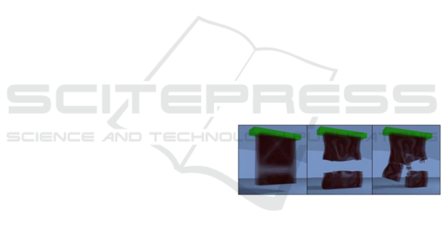
Figure 1: Stylistic control over the tearing process.
Comparing the effects of γ on the tearing pattern, using the
same elastic properties. From left to right: a) Initial state (t
= 0sec); b) = 0:85 (t = 1sec); c) = 0:3 (t = 1sec).
This paper presents our research efforts towards
tearable soft-body simulation with an emphasis on the
following properties: First, a tearing method that
provides stylistic and directional control with simple,
easily implementable parameters that are independent
from, but work together with the underlying material
properties used for the elastic simulation. Second,
have the potential for a real-time implementation
without significantly compromising the accuracy of
the simulation.
Finally, be based on a dynamics framework that
can be embedded or extended into a unified physics
solver (easy transition, extension and coupling with
256
Hesham, O., Joslin, C. and Ansara, R.
Interactive Anisotropic Tearing of Elastic Solids.
DOI: 10.5220/0006623902560263
In Proceedings of the 13th International Joint Conference on Computer Vision, Imaging and Computer Graphics Theory and Applications (VISIGRAPP 2018) - Volume 1: GRAPP, pages
256-263
ISBN: 978-989-758-287-5
Copyright © 2018 by SCITEPRESS – Science and Technology Publications, Lda. All rights reserved

other physical systems like fluid and cloth dynamics.)
With those goals in mind, we set out to achieve
the following:
Extending Becker et al.’s Smoothed Particle
Hydrodynamics (SPH) elastic simulation framework
(2009) to support topological changes through tearing
(or fracture, terms used interchangeably). Their
meshless framework was chosen for its realistic
simulation of elasticity at real-time rates while also
being extensible to fluid and rigid simulation, as
previously demonstrated by (Solenthaler et al., 2007).
Proposed the concept of a fracture disk that is
inserted at any point of fracture throughout the
simulation domain and, with the aid of an empirically
developed transparency map, affords the end user a
degree of control over the style of the tear (sharp and
clean-cut vs. soft and feathered), decoupled from the
elastic properties of the soft body being torn.
To control the tearing direction, we propose an
anisotropic tearing model that uses a vector field,
called fibres, to influence the orientation of the tear in
an isotropic material. We propose the use of strain-
rate to modulate this influence and to avoid a
completely geometric and artificial tearing pattern.
We also describe a fast and simple method of
maintaining the fibre field definition during the
simulation, while robustly handling situations of
fracture and topological changes in the material.
2 BACKGROUND
Since Terzopoulos et al.’s (1988) seminal work on the
dynamic simulation of deformable bodies and their
fracture, this area of computer graphics research has
seen a rapid increase in development, focusing on
stable, visually realistic and efficient methodologies
for simulating various natural physical phenomenon.
Specific to fracture simulation, earlier methods
heavily featured the Finite Element Method (FEM)
discretization, thanks to its connected mesh definition
and the ease of disconnecting them wherever fracture
events occurred. FEM also provided the desirable
property of convergence (as the resolution of the
mesh increases, the method approaches the true
continuum solution) and facilitated textured surface
embedding by simply treating the boundary faces of
the FEM mesh as the visual surface to render. Early
examples of efficient FEM fracture include O’Brien
et al.’s (1999) and its extension to ductile fracture
(O’Brien et al., 20020) and Irving et al.’s (2004) very
stable formulation for large and even inverted mesh
deformations. FEM found further practical use in
real-time gaming environments (Parker and O’Brien,
2009) and specialized medical and surgical scenarios
(Meier et al., 2005). However, remeshing around
topological changes while avoiding the generation of
irregularly shaped and problematic elements remains
a non-trivial challenge for FEM methods. This is
important in tearing simulation, considering the need
for fracture lines that cut through the mesh at arbitrary
locations.
Recent adaptive remeshing techniques (Hahn and
Wojtan, 2016), have tackled this problem, some even
providing a high level of control of the fracture
dynamics (Pfaff et al., 2014) with convincing visual
realism. Koschier et al., (2017) proposed an approach
based that decouples cut geometry from the
underlying FEM mesh, avoiding the need for
remeshing when tearing complex-shaped objects.
FEM and XFEM methods are still, however, far from
any real-time implementation, making them unviable
for interactive environments.
An approach proposed in Chen et al.’s work
(2014) comes closest to our goals of providing visual
control over the cut features. While fast, it contrasts
to our proposed method in two aspects. First, their
approach is done in a post-process that modifies the
FEM mesh geometrically while ours is done during
runtime. Second, our approach relies on a meshless
physics formulation.
Meshless methods have attracted attention for
their flexibility and resampling freedom. In essence,
the domain is discretized into disconnected particles
(nodes) where the dynamic properties are evaluated,
and each has an influence on the rest of the continuous
body that decreases as we go further away from it.
They do not suffer from the remeshing problems of
FEM methods and have been found particularly
useful for fracture simulation. Müller et al. (2004)
used moving least squares (MLS) to calculate a first-
order-accurate estimation of the deformation gradient
and successfully showcased the versatility of
meshless methods in handling elastic, plastic and
viscoelastic simulation seamlessly in the same
framework and at interactive rates.
Smoothed particle hydrodynamics (SPH) is a
meshless method, originally developed a few decades
ago to model cosmo-galactic events (Gingold and
Monaghan, 1977), that later became very popular in
computer graphics for real-time Lagrangian fluid
simulation due to its ability to handle rapidly
changing neighbourhoods with high temporal
coherency and stability (Müller et al., 2003; Tan and
Yang, 2009). Solenthaler et al., (2007) devised an
SPH framework to model a relatively large variety of
physical phenomenon including rigid, deformable
and fluid objects. However, their elasticity
Interactive Anisotropic Tearing of Elastic Solids
257

formulation suffered from being rotationally variant,
causing incorrect handling of rotating elastic bodies
that relied on an initial reference position. This was
later corrected by Becker et al., (2009) in their
corotated SPH formulation for elastic bodies.
Liu et al., (2011) presented a meshless method to
simulate fracture in brittle solids. They used rigid
dynamics for regular simulation and the Meshless
Local PetricGalerkin (MLPG) method to evaluate
stresses throughout the body during a fracturing
event. User control over the fracture pattern was
allowed through a custom weighted vector field to
guide the clustering part of their algorithm. While this
approach is fast and works well for brittle fracture in
rigid solids, it also forces the creation of a new
partition at every fracturing event, making it
unsuitable for our elastic soft body tearing where
partial cuts are allowed.
One of the few real-time medical simulators that
provides anisotropic tearing is Allard et al.’s cataract
surgery simulator (2009). In their implementation,
they use a 2D FEM model along with a vector field
(they called fibre field) to define the desired direction
of tear propagation. In contrast to the previously
discussed methods, however, their approach is purely
physical, relying on a complete anisotropic elasticity
simulation, which in turn directly results in
anisotropic tearing simulation. While their results are
convincing, their method does not allow for
anisotropic fracture control in isotropic materials.
The proposed method presented in this short paper
is largely based on work first introduced in (Hesham,
2011) which incorporates tearing into Becker’s
(2009) corotated SPH approach, and further
influenced by the concepts in Allard et al.’s (2009)
and Liu et al.’s (2011) research.
3 METHODOLOGY
We start by describing how fracture is visually
encoded using fracture disks and allowed to exist in
semi-arbitrary locations, followed by
parametrizations that allow control over the visual
detail of the fracture pattern without disturbing the
underlying physical mechanics and finally,
incorporating controllable anisotropic influence on
the tearing direction. We apply our tearing
modifications while striving for minimal impact on
the computational cost of the already efficient elastic
simulation.
3.1 Tearing
3.1.1 Fractured Kernel Shape Functions
In FEM or Mass-Spring System (MSS) simulations,
the discretized simulation nodes have well defined
connections that can be removed or split apart to
introduce fracture and topological change into the
model. Meshless methods like SPH, on the other
hand, do not have this kind of explicit connectivity
between its smoothed particles. What we can do,
however, is modify the weighted kernel shape
functions, such that nodes separated due to fracturing
no longer continue to influence the displacement field
gradient calculation, even if those nodes are still
within each other’s neighbourhood radius h.
For this purpose, Baleytschko et al., (2003)
introduced discontinuities in the SPH kernel shape
functions using a visibility criterion. Two nodes
within each other’s neighboorhoods can no longer
interact with each other if the ray passing through
them intersects a crack surface. This prevented the
shape functions from crossing the crack, but
introduced abrupt discontinuities in ▽u on both sides
of the crack, not just across it. This prompted Organ
et al., (1996) to introduce transparency to the
visibility check, providing a smoother outcome for
the modified shape functions and better transitions
near the tip of the crack front. We follow this
approach and develop our own transparency criteria,
motivated by empirical results and the afforded
controllability of the tearing style.
Every particle i stores a visibility value A
ij
[0, 1]
for every particle j in its neighbourhood, where 0
means the particles can completely see each other and
1 indicates no visibility at all. This is symmetric, so
A
ij
= A
ji
. The value is used to artificially increase the
distance between
and
for the kernel
computation in equation for both particles. So, the
new distance metric used for r becomes:
(1)
A crack surface is defined as a round disk centred at
position c with axis vector a and radius k. Wherever
a fracture event is detected, a new disk is inserted. The
criteria for determining the disk location and
orientation is discussed in sections 3.1.2-3.2.2. Once
inserted, we trigger a visibility check for all nearby
particles: for a given particle i, we trace a ray to each
of its neighbours j and denote the location of
intersection of each ray with the fracture disk as d
ij
.
The opacity
ij
at that point on the disk gets added to
the principle opacity A
ij
. The opacity [0, 1] is
radially defined on the disk as:
GRAPP 2018 - International Conference on Computer Graphics Theory and Applications
258
(2)
where γ [0, 1] defines the rigidity of the fracture
giving the user control over how the fracture
propagates locally. Visually, k can be thought of as
the radius of an inner disk that is completely opaque
(α = 1) and the rest of the disk gets gradually more
trans-parent as we move closer to the outer edge,
radius k, of the disk. Figure 2 shows the gradual effect
of disk transparency on the kernel shape function for
particle i.
The α
ij
value is the same for both particles (α
ij
=
α
ji
). If multiple disks are inserted in the same time step
(frame) of animation, the α
ij
obtained from all the disk
visibility checks are treated additively and A
ij
is
updated before discarding all the disks at the end of
the frame. A
ij
can only increase, as we treat fracture
damage as permanent, and once it reaches 1, the
particles are dropped from each other’s
neighbourhood lists and are never used again in each
other’s ▽u calculation. Also, as a general rule, if the
particles become too distant from each other ||x
i
- x
j
||
> 2.5h, we drop them from their corresponding lists,
regardless of A
ij
. Note that while the visibility check
is done using the current deformed state with
positions x
i
and x
j
, the neighbourhood update is done
on the initial state
and
as that is where the
elastic structure is originally defined.
High γ values produce very rigid and clean cuts,
whereas lower values produce softness in the fracture
lines and interesting patterns will arise (Figure 3 and
Figure 1). Of course, values can also be defined
globally or specified locally per node. We empirically
found γ =1 to be a suitable default value.
The method presented in this section is a simple user-
friendly way to alter the dynamic style of fracture,
affording flexibility of design and working alongside
(without being restricted by) the physical parameters
used for elasticity simulation.
3.1.2 Fracture Criteria
Fracture or tearing is initiated at any point in the body
where the maximal eigenvalue of the stress tensor
exceeds the material threshold. For an isotropic
material, the crack is propagated orthogonally to the
corresponding eigenvector.
The stress criteria are evaluated at every particle
in the simulation and we can directly begin the crack
at the location of that node. However, arbitrary crack
locations that are not dependent on the particle
distribution are also very easily. Part of what makes
meshless methods attractive for fracture simulation is
their inherent flexibility with resampling, allowing
the freedom to insert particles without worrying about
proper remeshing as with FEM methods.
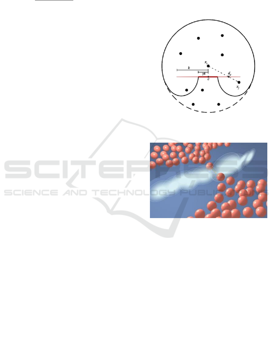
Figure 2: Effect of a visibility check through a fracture disk
(red) on the kernel shape function (thick line) with
influence radius h (dotted circle).
Figure 3: Effect of transparent fracture disks on the fracture
style. High γ values produce stiff fractures akin to brittle
fracture; while low γ produces “softer” tearing, with
interesting small-scale effects like shown here, where part
of the fractured object still seems to be “hanging by a
thread”, as seen when tearing a fibrous body (e.g. an
orange).
Our goal is still primarily an interactive
application, and although resampling might increase
accuracy, it could result in an unpredictable increase
in the number of simulation nodes and effectively
penalize simulations with a high count of fracturing
events.
Our crack location method begins with a node
whose principal stress (eigenvalue) v
i
has exceeded
the material fracture threshold. We obtain the
corresponding stress eigenvector
and the
orthogonal fracture direction z
i
. A fracture disk is
inserted with c = x
i
, a =
and k = h + 2(
).
Interactive Anisotropic Tearing of Elastic Solids
259

We then split the neighbourhood of particle i into Left
and Right neighbourhoods by the plane containing z
i
and whose normal is in
. The weighted average of
the maximal stresses is calculated for each side
independently as Left and Right:
h
(3)
(4)
The main idea here is to find out which side is more
stressed, and this bias informs us of where the fracture
would have most likely occurred. Finally, we perturb
the crack location from its original position x
i
along
the stress vector
by an amount directly
proportional to the difference between Left and Right.
Since meshless methods are inherently denser
than FEM methods, we find this minimal approach
reasonable for finding a physically-motivated
arbitrary crack location without sacrificing
computational efficiency.
3.2 Anisotropic Tearing
In this section we describe the specifics related to
anisotropic control over the tearing direction, using
terminology analogous to fibres found in biological
tissue (Allard et al., 2009).
3.2.1 Fibre Orientation Update
In our physics model, we allow a user-controlled
vector field over the simulation particles to denote the
desired directional influence on the tear propagation.
Each vector is called a fibre, and is conceptualized as
a 1-dimensional thread flowing through the body of
the object. We assume that the fibres fill up the 3D
domain of the simulation. That is, any particle lying
within the continuum of the object has a single fibre
passing through it, indicating the preferred direction
of tearing at that particle. These threads give strength
to the material along their main vector and resist
tearing across it.
The fibrous structure of the object is discretized
into a vector field over our existing set of simulation
particles P. Every particle is initialised with the 3D
vector
indicating fibre direction through that
particle position. The directions can be defined
globally, generated procedurally (for example
following the curvature of the object), or setup by
hand using 3D brushes or other manual techniques.
Linear, quadratic or quaternion interpolation can be
used to find the intended fibre direction at arbitrary
points throughout the domain.
As the simulation progresses and the object is
deformed by elastic and external forces, we need to
update the direction of the fibre to reflect the true fibre
structure in the deformed state, because elastic forces
do not produce local torque. This was not a problem
in Liu et al.’s (2011) meshless brittle fracture
simulation because they used rigid body dynamics
and could correctly maintain the fibre direction
throughout the simulation. Elastic FEM methods, like
(Allard et al., 2009), can simply embed the fibre
within each triangle (2D) or tetrahedron (3D) and
track the orientation as the simplex deforms.
We initially experimented with an implicit
definition of
, so for a certain particle i, we chose a
neighbouring particle j such that
as provided
the closest approximation to the user input direction
i. Once initialised, this link between i and j is constant
throughout the simulation. This method was simple to
implement, and gave a very stable non-jittery
definition of
, but we soon realised its
disadvantages. The first obvious problem was that the
fibre structure became entirely dependent on the
initial distribution of particles, hence we could not
truly define arbitrary fibre directions. Additionally,
having the direction coupled with a single particle j
meant that
, was no longer aware of deformations
on the opposite side of i and would not update the
fibre at i accordingly. Lastly, further maintenance was
required when a fracturing event separated i from j,
requiring us to find a new suitable neighbour j for i. It
quickly became apparent that this approach was not
robust enough for our tearable simulation.
We opted instead for an explicit definition of
(Figure 4). Becker et al.’s (2009) corotated SPH
formulation that we already use to evaluate elastic
dynamics, provides a rotation matrix, R
i
, which
encodes the local rotational variance from the initial
undeformed shape. This gave us a very stable and
efficient way to locally update the current fibre
direction
:
(5)
where
(or
, we do not differentiate between
them) is now just the initial vector definition of the
fibre, centred at x
i
and is no longer restricted to the
distribution of the particles, and the current ɸ
i,
is not
affected by fracturing events.
GRAPP 2018 - International Conference on Computer Graphics Theory and Applications
260

Figure 4: Fibre orientation maintenance. From left to right:
undeformed particles with initial fibre direction
;
deformed particles with no update to fibre direction;
deformed particles with explicit fibre update ɸ
i,
= R
i
.
3.2.2 Anisotropic Influence of Fibre on the
Tearing Direction
In this section, we describe how fibre orientation is
used to influence the fracture direction z in 3.1.2,
resulting in the desired anisotropic fracture.
Fibres in our simulation are there to resist tearing
across the fibre’s main direction. Given the plane
whose normal is
,
we want to suppress the
component of the fracture vector z
i
in the direction of
its projection onto
.
The new fracture vector is then:
(6)
where
is a penalty term deciding the magnitude of
the fibre’s influence (0 = completely follow fibre
direction; 1 = no fibre influence at all). What
distinguishes our implementation from previous
penalty-based anisotropy models (Liu et al., 2011) is
that in addition to allowing user-input values for
,
we improve the simulation realism by also
considering the physical rate of deformation (strain
rate
) for varying
. The faster the rate of
deformation is, the less the fibre can influence the
tear’s
direction. The effect of our approach can be
seen in Figure 5.
4 RESULTS
4.1 Implementation
We implemented our elasticity and tearing models by
extending the open source SPH simulator FLUIDSv.2
(Hoetzlein and Höllerer, 2008), resulting in a system
that can simulate both fluids and tearable elastic
bodies. The code is written in C++ and utilizes
OpenGL for graphical output.
The particles in all of our tests are on average 0.05
units apart with an influence radius h = 0.2. The
number of neighbours a particle can have within its
influence radius is limited to the nearest 20. This
allows us to use an adjacency list to maintain
neighbourhood information quite efficiently. In
addition, we inserted our deforming particles into a
spatial hash as described in Viccione et al. (2008),
which is a standard way to accelerate broad-phase
collision detection and fluid neighbourhoods, but we
also use it to quickly find the grid(s) around an
inserted fracture disk, performing the disk visibility
check on only those particles.
4.2 Performance and Results
We successfully achieve interactive rates in our tests,
with our profiler indicating that our calculations take
an average of 62% of the total processing time per
frame, with the rest for rendering and other processes.
These results, while not distinguished from similar
purely elastic simulation models, show considerable
speed-up when compared to similar fracturing
simulations, in some cases even an order of a
magnitude faster, as shown in Table 1. We do note
that surfacing would incur additional costs, but our
physical fracturing simulation speeds already seem
promising. We compare our method with other
meshless techniques in computer graphics that allow
soft-body tearing. We also include the performance of
Becker et al., (2009), the purely elastic framework
that we extended, to show that our tearing method
does not present a large computational penalty, even
in situations with relatively high particle count. As the
number of fractured partitions increased, our
simulation got faster due to a reduced neighbourhood
list. Figure 5 shows an example of an elastic soft body
hanging from a static support bar (green) and getting
torn by its own weight. Figure 4 shows how we
enhance the realism of anisotropic tearing by
considering the velocity of deformation, strain rate.
As with every physics simulator in computer
graphics, stability is an important factor to consider in
our tests and implementation design. We use the
Verlet variant of the Leapfrog integration (Nealen et
al., 2006), to advance our simulation, which was fast
to solve and provided a high degree of stability.
Complex cases benefited from increasing particle
samples and decreasing the timestep, at an added
computational cost. Generally, SPH fluid pressure
forces were also useful to maintain stability for larger
time steps (Becker et al., 2009; Müller et al., 2004).
We also found it helpful to spread the fracture disk
insertion process over several frames (4 to 10) by
scaling the disk size from 0.25k to k. Aside from being
a reasonable reflection of reality, this had a
favourable impact on our computational and visual
stability.
Interactive Anisotropic Tearing of Elastic Solids
261
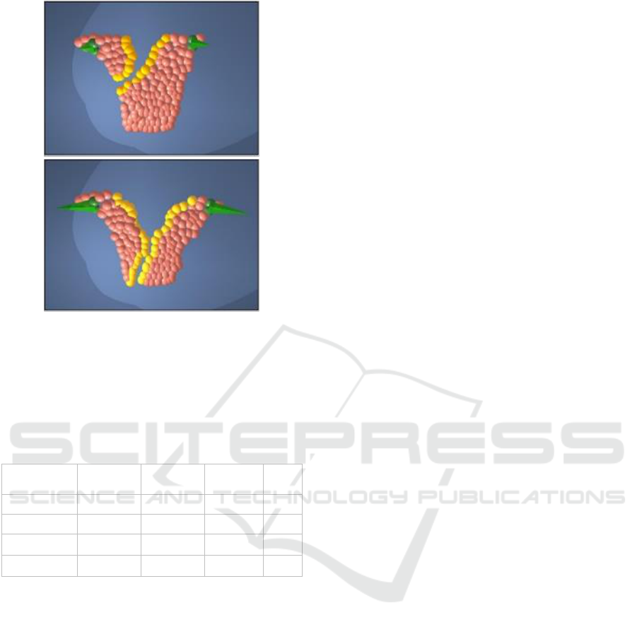
Figure 5: An originally rectangular soft body with diagonal
fibres pointing north-east being torn apart by external forces
(green cones). Top: peeling the object slowly allows the
fibre to dictate the tearing direction. Bottom: a faster strain-
rate correctly reduces the anisotropic influence of fibre,
closely resembling tearing in a fibre-free object.
Table 1: Performance results for samples shown in this
report.
Sample
Particles
γ Tear
Rigidity
Δt(ms)
FPS
Figure 3.
700
0.5
5
65
Figure 5.
300
0.9
5
86
Figure 1b.
24000
0.85
5
37
Figure 1c.
24000
0.3
5
34
While evaluating our explicit fibre tracking
method (Section 3.2.1), we observed that temporal
coherency of the fibre orientation was not perfect (i.e.
it seemed a bit jittery) for particles near the surface of
newly created fractures. We believe this happens
because the SPH-based rotation estimation R has
lesser accuracy due to a reduced number of
neighbouring particles compared to the neighbours at
the initial reference positions. The effect on the
simulation, however, was negligible and the method
is overall very sufficient for a fairly accurate and
robust maintenance of fibre direction. We also
noticed that it performs quite well with primarily
dilation-based de-formations (stretch and
compression), however it struggles to maintain the
fibre orientation accurately when the object is
subjected to large shear deformations. We attempted,
unsuccessfully, to remedy this by extracting the local
shear information from the Jacobian of the
displacement field to inform the fibre orientation. We
suspect that a mixed explicit-implicit fibre update
method would help greatly in this situation.
5 CONCLUSIONS
This short paper has presented a method for soft-body
tearing that emphasizes controllability, speed and
stability without significantly compromising realism
and accuracy, all of which are desired aspects in
game, film and medical simulation development. We
provided simple parametrizations for two interesting
phenomena in tearing simulation. The first, controls
how clean (brittle-looking) the cuts are; and the
second involved anisotropic control of the tearing
direction for mechanically isotropic materials using
embedded virtual fibres in the de-formable body.
We have shown how to incorporate our approach
into an existing soft-body simulator by extending an
elastic solids SPH framework, chosen due to the
versatility of meshless methods in fracturing
simulations and their suitability for extension into
unified physics solvers that directly interact with
other meshless simulants such as fluids.
While the observed performance of the method in
this poster is encouraging, this work requires further
validation against real-life scenarios, particularly
building a database of parameterization for tearing of
various fibrous objects (e.g. fruits and vegetables) and
organic tissue. It would also benefit from comparative
analysis against the established state-of-the-art in
near real-time soft-body tearing. Blobby-sphere
based surfacing would suffice for rudimentary
examination of the results, but more sophisticated
surfacing methods warrant study.
Medical soft tissue that exhibits highly non-linear
and anisotropic behaviour (Zohdi, 2007) is difficult to
simulate and tear accurately in real-time. This would
involve extending our anisotropic component to
model more sophisticated fibre fields including grids
and 2D strips, in addition to accounting for
anisotropy, not just in tearing, but in the mechanical
behaviour itself where the material stress thresholds
vary across different directions.
ACKNOWLEDGEMENTS
This project was funded by The Interactive and Multi-
Modal Experience Research Syndicate (IMMERSe).
GRAPP 2018 - International Conference on Computer Graphics Theory and Applications
262

REFERENCES
Allard, J., Marchal, M. and Cotin, S., 2009. Fiber-based
fracture model for simulating soft tissue tearing. Studies
in health technology and informatics, 142, pp.13-18.
Becker, M., Ihmsen, M. and Teschner, M., 2009, March.
Corotated SPH for Deformable Solids. In NPH (pp. 27-
34).
Belytschko, T., Chen, H., Xu, J. and Zi, G., 2003. Dynamic
crack propagation based on loss of hyperbolicity and a
new discontinuous enrichment. International Journal
for Numerical Methods in Engineering, 58(12),
pp.1873-1905.
Chen, Z., Yao, M., Feng, R. and Wang, H., 2014. Physics-
inspired adaptive fracture refinement. ACM
Transactions on Graphics (TOG), 33(4), p.113.
Gingold, R.A. and Monaghan, J.J., 1977. Smoothed particle
hydrodynamics: theory and application to non-spherical
stars. Monthly notices of the royal astronomical society,
181(3), pp.375-389.
Hahn, D. and Wojtan, C., 2016. Fast approximations for
boundary element based brittle fracture simulation.
ACM Transactions on Graphics (TOG), 35(4), p.104.
Hesham, O., 2011. Fast Meshless Simulation of
Anisotropic Tearing in Elastic Solids (Thesis, Carleton
University Ottawa).
Hoetzlein, R.C. and Höllerer, T., 2008. Analyzing
Performance and Efficiency of Smoothed Particle
Hydrodynamics.
Irving, G., Teran, J. and Fedkiw, R., 2004, August.
Invertible finite elements for robust simulation of large
deformation. In Proceedings of the 2004 ACM
SIGGRAPH/Eurographics symposium on Computer
animation (pp. 131-140).
Koschier, D., Bender, J. and Thuerey, N., 2017. Robust
eXtended finite elements for complex cutting of
deformables. ACM Transactions on Graphics (TOG),
36(4), p.55.
Liu, N., He, X., Li, S. and Wang, G., 2011. Meshless
simulation of brittle fracture. Computer Animation and
Virtual Worlds, 22(2‐3), pp.115-124.
Meier, U., López, O., Monserrat, C., Juan, M.C. and
Alcaniz, M., 2005. Real-time deformable models for
surgery simulation: a survey. Computer methods and
programs in biomedicine, 77(3), pp.183-197.
Müller, M. and Gross, M., 2004, May. Interactive virtual
materials. In Proceedings of Graphics Interface 2004
(pp. 239-246).
Müller, M., Charypar, D. and Gross, M., 2003, July.
Particle-based fluid simulation for interactive
applications. In Proceedings of the 2003 ACM
SIGGRAPH/Eurographics symposium on Computer
animation (pp. 154-159).
Müller, M., Keiser, R., Nealen, A., Pauly, M., Gross, M.
and Alexa, M., 2004, August. Point based animation of
elastic, plastic and melting objects. In Proceedings of
the 2004 ACM SIGGRAPH/Eurographics symposium
on Computer animation (pp. 141-151).
Nealen, A., Müller, M., Keiser, R., Boxerman, E. and
Carlson, M., 2006, December. Physically based
deformable models in computer graphics. In Computer
graphics forum (Vol. 25, No. 4, pp. 809-836).
O'Brien, J.F. and Hodgins, J.K., 1999, July. Graphical
modeling and animation of brittle fracture. In
Proceedings of the 26th annual conference on
Computer graphics and interactive techniques (pp.
137-146).
O'Brien, J.F., Bargteil, A.W. and Hodgins, J.K., 2002.
Graphical modeling and animation of ductile fracture.
ACM transactions on graphics (TOG), 21(3), pp.291-
294.
Organ, D., Fleming, M., Terry, T. and Belytschko, T., 1996.
Continuous meshless approximations for nonconvex
bodies by diffraction and transparency. Computational
mechanics, 18(3), pp.225-235.
Parker, E.G. and O'Brien, J.F., 2009, August. Real-time
deformation and fracture in a game environment. In
Proceedings of the 2009 ACM SIGGRAPH/
Eurographics Symposium on Computer Animation (pp.
165-175).
Pfaff, T., Narain, R., de Joya, J.M. and O'Brien, J.F., 2014.
Adaptive tearing and cracking of thin sheets. ACM
Transactions on Graphics (TOG), 33(4), p.110.
Solenthaler, B., Schläfli, J. and Pajarola, R., 2007. A unified
particle model for fluid–solid interactions. Computer
Animation and Virtual Worlds, 18(1), pp.69-82.
Tan, J. and Yang, X., 2009. Physically-based fluid
animation: A survey. Science in China Series F:
Information Sciences, 52(5), pp.723-740.
Terzopoulos, D. and Fleischer, K., 1988, August. Modeling
inelastic deformation: viscolelasticity, plasticity,
fracture. In ACM Siggraph Computer Graphics (Vol.
22, No. 4, pp. 269-278).
Viccione, G., Bovolin, V. and Carratelli, E.P., 2008.
Defining and optimizing algorithms for neighbouring
particle identification in SPH fluid simulations.
International Journal for Numerical Methods in Fluids,
58(6), pp.625-638.
Zohdi, T.I., 2007. A computational framework for network
modeling of fibrous biological tissue deformation and
rupture. Computer Methods in Applied Mechanics and
Engineering, 196(31), pp.2972-2980.
Interactive Anisotropic Tearing of Elastic Solids
263
