
Perception Enhancement for Bionic Vision
Preliminary Study on Object Classification with Subretinal Implants
Johannes Steffen
1
, Jonathan Napp
1
, Stefan Pollmann
2, 3
and Klaus T
¨
onnies
1
1
Department of Simulation and Graphics, Otto-von-Guericke University, Magdeburg, Germany
2
Department of Experimental Psychology, Otto-von-Guericke University, Magdeburg, Germany
3
Center for Brain and Behavioral Sciences, Otto-von-Guericke University, Magdeburg, Germany
Keywords:
Bionic Vision, Retinal Implants, Artificial Neural Networks, Object Classification.
Abstract:
The restored vision by using subretinal implants of patients suffering from a loss of photoreceptors, e.g., in
retinitis pigmentosa and age-related macular degeneration, is, compared to healthy subjects, very limited.
Therefore, we investigated, whether it is possible to enhance the perception of such patients by transforming
the input images in a systematic manner. To this end, we propose a new image transformation network that is
capable to learn plausible image transformations in an end-to-end fashion in order to enhance the perception
of (virtual) patients with simulated subretinal implants. As a proof of concept, we test our method on an
object classification task with three classes. Our results are promising. Compared to a baseline model, the
overall object classification accuracy increased significantly from 67.4% to 81.1%. Furthermore, we discuss
implications and limitations of our proof of concept and outline aspects of our work that can be improved and
need to be subject of further research.
1 INTRODUCTION
Degenerative retinal diseases are one of the main
causes of vision loss. Particularly, age-related mac-
ular degeneration (AMD), is the most common cause
of vision impairment in the United States and the
fourth most common cause globally (Vos et al., 2015;
The Eye Diseases Prevalence Research Group, 2004).
Moreover, retinitis pigmentosa (RP) is another de-
generative disease of the retina that typically affects
younger patients and, in contrast to AMD, leads to a
loss of peripheral vision first and may, however, lead
to complete blindness over the course of the disease
due to the degeneration of the photoreceptors within
the retina (Busskamp et al., 2010) (see Figure 1b).
Although, both of the aforementioned diseases have
different pathologies they will lead to non-functional
photoreceptors that, subsequently, hamper the signal
processing within the retina and cause different but
significant loss of vision.
1.1 Vision Restoration
During the last decade, efforts were made to par-
tially restore the loss of vision of patients suffer-
ing from blindness due to RP and, potentially, also
AMD. Specifically, retinal implants were introduced
to stimulate the still intact neurons within the retina.
For retinal implants, a microchip with an electrode
array is implanted in the eye to replace the non-
functional photoreceptors, that were formerly respon-
sible to convert light into electrical current for further
signal processing. This is possible, because in most
degenerative retinal diseases only the photoreceptors
are dysfunctional and the subsequent processing lay-
ers of the retina are still (partially) intact. Thus, the
general goal is to feed the remaining functional neu-
rons with electrical stimuli to partially restore vision.
The normal, non-pathological vision processing
pipeline in humans begins with the transduction of in-
coming light into electrochemical signals through the
photoreceptors inside the retina. After transduction,
the signal is passed through various processing lay-
ers inside the retina. These layers consist of different
types of cells, e.g., bipolar-, amacrine-, horizontal-,
and ganglion cells, where the axons of the latter form
the optical nerve. Afterwards, the information is fur-
ther processed inside the brain.
However, the signal processing for AMD and RP
patients is severely deficient. Starting at the inner lay-
ers of the retina, photoreceptors, bipolar cells, and
ganglion cells can be degenerated to a great extent
leading to either complete or partial loss of vision. For
a successful restoration of vision it would be benefi-
cial to feed signals into the remaining bipolar cells,
thus, bypassing the degenerated photoreceptors by
Steffen, J., Napp, J., Pollmann, S. and Tönnies, K.
Perception Enhancement for Bionic Vision - Preliminary Study on Object Classification with Subretinal Implants.
DOI: 10.5220/0006648901690177
In Proceedings of the 7th International Conference on Pattern Recognition Applications and Methods (ICPRAM 2018), pages 169-177
ISBN: 978-989-758-276-9
Copyright © 2018 by SCITEPRESS – Science and Technology Publications, Lda. All rights reserved
169
Sclera
Choroid
Retina
Optical Nerve
Lens
Pupil
Iris
Ganglion Cell
Bipolar Cell Rod
Cone
Choroid
Degenerated
Photoreceptors
with
Subretinal
Implant
Optic Fiber Layer
Inner Nuclear Layer
Retinal Pigment Epithelium
b)a)
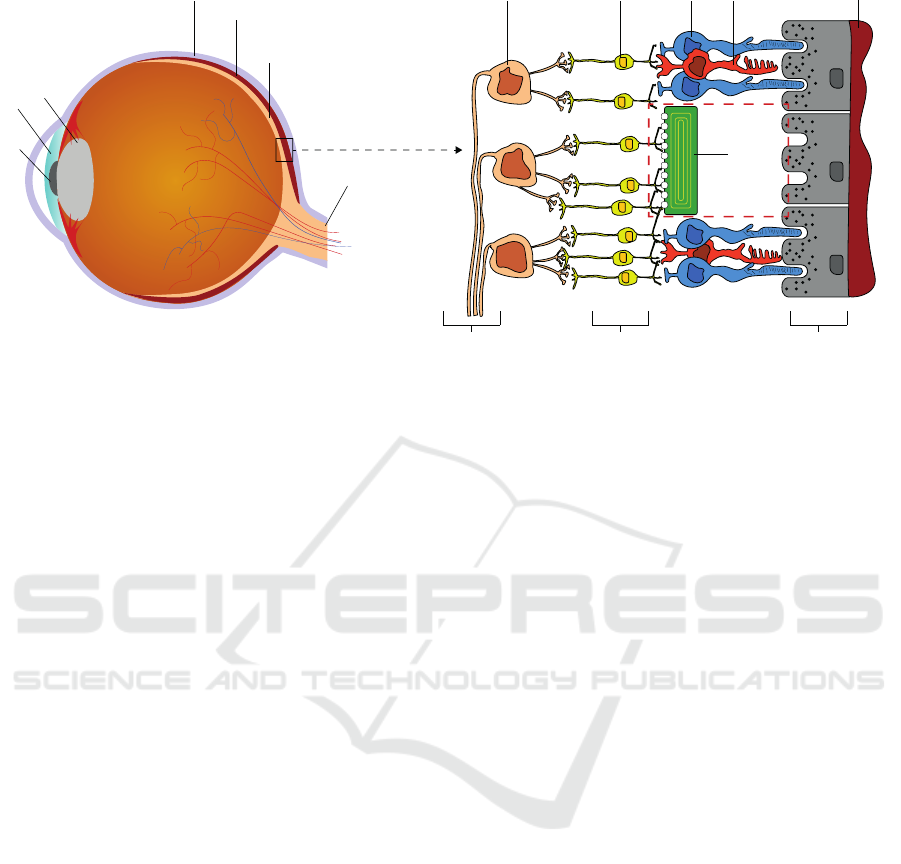
Figure 1: a) Simplified cross section of a human eyeball. The light hits the retina, where photoreceptors convert it into
electrochemical signals that are further processed in subsequent layers of the retina. b) Magnified and simplified version of a
small section of the retina. The most outer part consists of the retinal pigment epithelium, where the photoreceptors (rods and
cones) lie on. The information is then forwarded through the inner nuclear layer consisting of (among others) bipolar cells
for further feature extraction. The ganglion cells forward the signal through their axons (optic fiber layer) into the optical
nerve. Due to the dense neuronal network built by the bipolar-, amacrine-, and horizontal cells inside the inner nuclear layer,
the implant cannot be placed on top of the retina (epiretinal) but is placed inside the area of degenerated photoreceptors (red
dashed box) stimulating the connected bipolar cells instead.
converting light inside a microchip and forwarding a
signal to the next cells in the retina, thereby, using the
computations carried out in the retina (Beyeler et al.,
2017). To achieve this, the electrode array has to be
implanted below the retina, at the physiological loca-
tion (subretinal) of the photoreceptors (Figure 1b).
It has to be noted, that there also exists another
type of retinal implant, i.e., an epiretinal implant. In
contrast to its subretinal counterpart, it is placed on
top of the retina inside the vitreous of the eye. The
implant is used to directly stimulate ganglion cells ly-
ing in the upper retinal layer (please refer to Figure
1). Thus, epiretinal implants are capable of effec-
tively bypassing all previous processing neurons and
directly feed their signal through the ganglion cells to
the optical nerve, omitting the retinal circuitry. This,
theoretically, could help to restore vision of patients
with severe damages in all previous layers. How-
ever, compared to the subretinal implant described be-
low, epiretinal implants like the Argus II system (Hu-
mayun et al., 2012) currently suffer from three ma-
jor disadvantages. First, it does not contain photo-
diodes but instead uses a camera mounted to special
glasses and, thus, patients cannot use eye movements
but need to move their head in order to search their en-
vironment. Second, the epiretinal electrodes will not
only directly stimulate ganglion cells but also axons
from other ganglion cells, which traverse the top of
the retina (Beyeler et al., 2017), and, third, the spatial
resolution of 6 × 10 electrodes is very limited.
We restrict ourselves to the case of subretinal im-
plants. The reason for this is twofold. First, we do not
expect significant enhancements when using epireti-
nal implants due to their low spatial resolution (i.e.,
the Argus II with 6 × 10 electrodes) and, second, we
do not need to model axonal streaks and the subse-
quent distortion of the perceived image due to the
placement of epiretinal implants.
1.2 Subretinal Implants
An example of a subretinal implant is the Alpha IMS
system (Stingl et al., 2013), that consists of a chip
with photodiodes and electrodes, so that it can di-
rectly stimulate still functional bipolar cells (Beyeler
et al., 2017). Bipolar cells are the first cells that nor-
mally receive input from the photoreceptors, so that
subretinal implants can use the computations inside
the retina, as long as the retinal cells are still intact.
Apart from this, the Alpha IMS has two more im-
portant advantages. First, eye movements are still
possible and, second, there are no distortions due to
axonal stimulations as in the case of epiretinal im-
plants (cf. (Humayun et al., 2012)). Furthermore, the
chip houses 1500 photodiode/electrode-pairs yielding
a potentially higher spatial resolution w.r.t. the afore-
mentioned epiretinal implant.
ICPRAM 2018 - 7th International Conference on Pattern Recognition Applications and Methods
170

1.3 Restoration and the Virtual
Patient’s Perception
Retinal implants, like the Alpha IMS can only con-
vey very limited information compared to normal vi-
sion. Among other reasons, this is due to the dra-
matically decreased spatial sampling and due to dif-
ferent kinds of artefacts. Thus, predicting the per-
ceived image of a patient with an implanted retinal
prosthesis is challenging and influenced by numer-
ous parameters, such as the type and the position of
the implant and its components, the progress of the
patient’s disease, and the amount and position of re-
maining functional neurons. Therefore, Beyeler et al.
proposed the pulse2percept
1
framework for simulat-
ing bionic vision upto the perceived image (Beyeler
et al., 2017). Specifically, they have modelled the sig-
nal processing of the inner nuclear layer (limited to
bipolar cells as depicted in Figure 1), the ganglion
cells, and the optic fiber layer. Their results where
validated by psychophysical and behavioural exper-
iments with patients (please refer to (Beyeler et al.,
2017) for more details). Following Beyeler et al. the
phrase virtual patient’s perception refers to virtually
perceived images that are based on a simulation.
Figure 2 shows two exemplary images and their
corresponding simulation results of a virtual patient’s
perception when vision is restored using a subretinal
implant. Here, the loss of information w.r.t. the orig-
inal images is clearly visible and the task of discrimi-
nating the two objects is challenging.
1.4 Motivation and Outline
Looking at the examples provided in Figure 2 it be-
comes apparent, that the quality of the restored bionic
vision is likely to be insufficient for everyday visual
tasks. Therefore, the question arises, whether it is
possible to enhance the perceived image of a virtual
patient in order to solve a visual task better than be-
fore. Since we do assume that we cannot directly alter
the signal processing by the implant itself (although
this might become possible in the future) the only way
to achieve potentially better perceptual images is to
transform the input image such that its processed ver-
sion is more useful to fulfil a specific task. However,
finding a good transformation of the original input im-
age is challenging. While it is a reasonable thought to
apply simple image manipulation, e.g., local contrast
enhancement and edge detection, it is hard to justify
the choice for such transformation.
1
https://github.com/uwescience/pulse2percept (Beyeler
et al., 2017)
Figure 2: Examples of simulated perceived images. Left
column: Original images taken from the ALOI data set
(Geusebroek et al., 2005). Right column: Simulation re-
sults of a virtual patient’s perception with a subretinal im-
plant like the Alpha IMS. The simulation results were ob-
tained by using pulse2percept.
1.5 An Extended Virtual Patient for
Object Classification
To overcome this limitation, we propose a new im-
age transformation neural network that is capable to
learn plausible image transformations in an end-to-
end fashion. Therefore, as a proof of concept, we
replace the pulse2percept simulation by a simple and
differentiable neural network, that enables us to opti-
mize arbitrary objective functions.
Since this work comprises a preliminary study, we
restrict ourself to a common object classification task.
Specifically, we are interested in whether it is possi-
ble to automatically learn an image transformation of
the original image such that the perceptual image of
the virtual patient provides better grounds for a sub-
sequent object classification task. Thereby, we limit
ourselves to the classification of three different object
classes to evaluate the general applicability of the pro-
posed approach.
To this end, we extend the virtual patient as intro-
duced in (Beyeler et al., 2017) by an artificial observ-
ing unit, which performs object classification based
on the virtual patient’s perceived images. Further-
more, we restrict ourselves to simulate the subretinal
Alpha IMS implant.
Perception Enhancement for Bionic Vision - Preliminary Study on Object Classification with Subretinal Implants
171
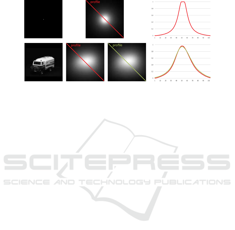
Figure 3: Top row: A black image with a white dot placed in the middle (left column) used to estimate a PSF out of the
simulation framework pulse2percept (middle column) and an exemplary intensity profile along its diagonal (right column).
Bottom row: An input image (first column), its simulated perceptual version from pulse2percept (second column), its sim-
ulated perceptual version as a result from convolving it with the estimated PSF (third column), and a comparison of the two
resulting intensity profiles along the respective diagonals (fourth column).
2 METHODS
As a proof of concept, we consider the retinal simu-
lation as a black box. The underlying function that
transforms an input image into a virtual patient’s per-
ceived image is, thus, unknown. However, our goal is
to develop an architecture that is capable to perform
end-to-end learning on various tasks - including ob-
ject classification. Therefore, we propose to model
the extended virtual patient as a neural network al-
lowing us to use iterative optimization methods, i.e.,
gradient descent, for arbitrary objective functions.
2.1 Replacement of the Retina
Simulator
To this end, instead of re-engineering the publicly
available software pulse2percept to be fully differen-
tiable and capable to be integrated inside a neural net-
work, we approximated the output of the simulation
by a simple point-spread-function (PSF) estimation.
It has to be noted, that this approximation is only valid
for a fixed set of parameters, namely, the position of
the subretinal implant inside the retina, the amount
of electrodes on the implant’s microchip, the size of
the electrodes, and their spacing. We set this param-
eters according to the specification of the Alpha IMS
subretinal implant (Koitschev et al., 2015) although
the authors assume, that any other plausible settings
could have been used to show the general applicabil-
ity of this approach. Using pulse2percept we simu-
lated the virtual patient’s perception of a single dot
for calculating the point-spread-function.
Figure 3 shows the estimated PSF (top row) with
an exemplary intensity profile along the diagonal of
the input image as well as an image (bottom row,
left) of which the perceived image is simulated by
pulse2percept (bottom row, second column), the re-
sult by replacing the simulation software by a simple
PSF (bottom row, third column), and a comparison of
exemplary intensity profiles (bottom row, forth col-
umn). While certainly not all details can be described
by a simple PSF the results indicate a sufficient ap-
proximation of the simulation and, thus, can be used
for a proof of concept.
2.2 Network Architecture
Extended Virtual Patient Network
Due to the fact that we are now able to replace the
perceptual simulation of the virtual patient by a sim-
ple convolution with a PSF it is now possible to model
the extended virtual patient as a neural network. Since
our virtual patient shall be capable of object classifi-
cation we extent the virtual patient with an artificial
observing unit, that, similar to the human brain, clas-
sifies simulated perceptual images into object cate-
gories. Hence, the extended virtual patient’s neural
network consists of two parts. The first part simulates
the transformation of an input image into the percep-
tual image by a simple convolution with the PSF. The
weights of this convolution are fixed and no bias term
is used to retain a simulation of the retinal processing.
The output of this convolution is then forwarded to the
artificial observing unit, which is modelled as a neu-
ral network consisting of a convolutional sub network
and a subsequent multilayer perceptron as a classifier.
ICPRAM 2018 - 7th International Conference on Pattern Recognition Applications and Methods
172
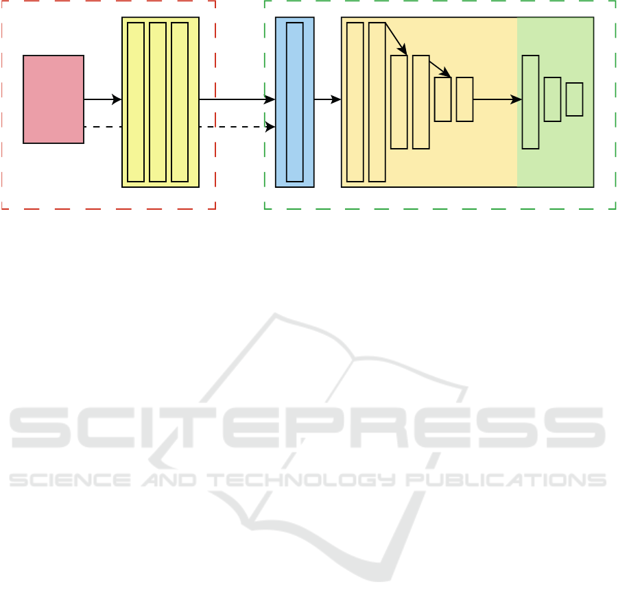
Image Transformation Network
MLPCNNCNN CNN
Extended Virtual Patient
Input Image
(104,104,1)
(104,104,32)
(104,104,32)
(104,104,1)
(104,104,1) FIXED - PSF
(104,104,32)
(104,104,32)
(52,52,64)
(52,52,64)
(26,26,128)
(26,26,128)
Max-Pooling
Max-Pooling
Max-Pooling
128
64
3
Kernel size: 5x5 Kernel size: 3x3
Figure 4: Overview of the used network architecture(s). An input image (red box) is fed to a convolutional neural network
performing a learned image transformation (yellow box). The transformed image is then fed to the extended virtual patient,
where a perceptual version of the transformed image is approximated by a PSF and then passed to an artificial observing unit
that classifies the image into one of the three object categories. The information flow of the baseline model is indicated by the
dashed arrow from the input image to the extended virtual patient, effectively bypassing the transformation CNN.
The convolutional sub network of the extended
virtual patient has three blocks, where each block con-
sists of two convolutional layers followed by a max-
pooling layer of stride 2 in both spatial dimensions.
The number of kernels per block is doubled after each
block starting at 32 kernels, the kernel sizes are fixed
at 3× 3 px, and ReLUs are used as activation functions
after each convolutional layer.
The output of the convolutional sub network is
then embedded into the one-dimensional space and
forwarded to a MLP consisting of three fully con-
nected layers with 128, 64, and 3 nodes, respectively.
For the first two fully connected layers ReLUs are
used as activation functions and a softmax activation
is applied on the last output to obtain the class mem-
bership of a given input. The green dashed box of
Figure 4 summarizes the used architecture.
Image Transformation Network
The input of the image transformation network is the
original image, of which its transformed version is
perceived and then classified by the extended virtual
patient. Under the assumption, that we seek for a
transformation based on local intensities and not on
global and semantically inferred information, the ar-
chitecture of this network was designed rather simple
and shallow. Specifically, it consists of three convo-
lutional layers, where the first two have 32 kernels
of size 5 × 5 each and the third having only 1 filter
as its output is the transformed gray-valued image.
Again, ReLUs are used as activation functions. The
red dashed box of Figure 4 summarizes the used im-
age transformation architecture.
2.3 End-To-End Network and Training
By combining the two aforementioned networks into
one model it is possible to learn image transformation
parameters in an end-to-end fashion that improve the
object classification quality of the artificial observer.
Thus, the image transformation parameters and the
weights of the artificial observer can be learned by
using standard error backpropagation. Moreover, ar-
bitrarily chosen differentiable objective functions can
be used to solve a variety of visual tasks.
3 EVALUATION
To test the proposed model, that combines an image
transformation network and the introduced extended
virtual patient, we perform a standard object classifi-
cation task with a small number of classes.
Datasets: The dataset comprises images of three
object classes, namely, airplanes, cars, and bicy-
cles. Images were obtained through a Google image
search. Images containing objects on homogeneous
backgrounds were removed, since we want to prevent
the artificial observer to exclusively learn object’s sil-
houettes, potentially contradicting real life sceneries.
The final dataset consists of 1250 gray-valued im-
ages per class. The images were resized to 104 × 104
px to assure, that the whole image can be projected
onto the subretinal implant’s microchip without any
further subsampling.
Perception Enhancement for Bionic Vision - Preliminary Study on Object Classification with Subretinal Implants
173
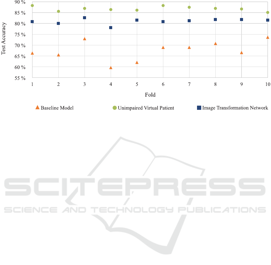
Figure 5: Test set accuracy across all folds for the three evaluated models. Please refer to the text in Subsection 3.1 for more
details.
Baseline Model: Our baseline model consists of the
extended virtual patient that receives the unaltered im-
ages. We test this model to ensure, that the power of
the artificial observing unit (the convolutional neural
network and its subsequent multilayer perceptron) is
factually limited and, thus, does not solve the task at
hand - i.e., no image transformation is needed at all
(see Figure 4 for an overview).
Unimpaired Virtual Patient For comparability, we
also evaluate the object classification quality of the
artificial observing unit when no impairment, thus, no
implant is present. This is done to show the general
classification capabilities of the observing unit.
Training: Our final model depicted in Figure 4,
the baseline model, and the unimpaired virtual pa-
tient model are trained in an end-to-end learning fash-
ion using stochastic gradient descent with a starting
learning rate of 0.01, momentum of 0.9, and a learn-
ing rate decay of 0.00008. Training is done for 125
epochs and a dropout (Hinton et al., 2012) of 50%
is applied after the first two fully connected layers of
the classification network (MLP). Categorical cross-
entropy is used as the objective function assessing the
loss of the object classification.
To evaluate the robustness of the proposed
method, we applied 10-fold cross-validation. There-
fore, the data set was split 10 times into a training and
testing set (90%/1125 training images, 10%/125 test-
ing images) and trained as described above.
3.1 Results and Discussion
The object classification quality of the testing set for
each of the 10 folds is depicted in Figure 5. As ex-
pected, the unimpaired virtual patient network, where
the artificial observing unit is trained on the original
input images performs best with an averaged test set
accuracy of 86.8%. This indicates the general appli-
cability of our described architecture of the artificial
observing unit. For the baseline model, the artificial
observing unit is trained with the approximated per-
ceived image of the virtual patient. As can be seen,
the overall quality of the classification degenerates
drastically resulting in an averaged test set accuracy
of 67.4%. Finally, when the image transformation
network is plugged into the network and the origi-
nal input images are transformed before they stimu-
late the implant of the virtual patient, the averaged
test set accuracy across the 10 folds significantly in-
creased to 81.1%. The results are promising w.r.t.
our restricted scenario and the overall accuracy gain
is 13.7%. Specifically, the results indicate that it is
possible to enhance a virtual patient’s perception by
a simple transformation of the retinal implant’s input
and, thus, before the retinal circuitry and without al-
tering the signal processing inside the microchip.
As can be seen in Figure 6 (third column), the im-
age transformation network learns to enhance edges
and blob-like structures of the original image. This
amplification of edges and local regions inside the
image seems to further improve local contrast in the
resulting perceptual images making them to appear
more detailed than their unaltered counterparts. The
transformation unit was constructed for providing lo-
cal feature transformations only since the result is fed
ICPRAM 2018 - 7th International Conference on Pattern Recognition Applications and Methods
174

as a spatially distributed input signal into the implant
simulator. Edges and blobs are considered important
local features for object recognition and, thus, the net-
work seems to deduce appropriate features directly
from the global classification task. The results of the
classifier also indicate that the learned transformation
seems to be adequate for the task.
However, we do note that our approach has se-
vere limitations and restrictions regarding the techni-
cal side as well as in its expressiveness of the results.
Regarding the former, we made the implicit under-
lying assumption that the simulation of the percep-
tual image that is used in our virtual patient is cor-
rect and sufficient for further investigations. How-
ever, it is likely that the underlying processing of
pulse2percept, on which we base our estimation of the
PSF, will be subject to changes. Furthermore, we have
to stress, that the approximation of the signal process-
ing by using a PSF is restricting and does certainly not
capture all important steps in simulating a perceived
image. Moreover, the results presented indicate a sig-
nificant quality gain in an object classification task for
a virtual patient but, to this end, we cannot directly
implicate that this is also true for real patients.
4 CONCLUSION
We motivated the idea of bionic vision enhancement
w.r.t. subretinal implants in a virtual patient. We pro-
posed to model the signal processing from an input
image to a perceptual image as a neural network al-
lowing us to learn a suitable image transformation
for arbitrary differentiable objective functions. As a
proof of concept, we demonstrated the general ap-
plicability of our approach on an object classifica-
tion task, where a virtual patient is extended by an
artificial observing unit that decides on an object’s
class membership. Comparing our results to a base-
line model in which no image transformation is ap-
plied, the overall classification accuracy is increased
by 13.7% indicating great potential to enhance ob-
ject classification of visually impaired virtual patients.
Furthermore, since the virtual patient as well as the
image transformation are modelled in a neural net-
work, our approach is not limited to the visual task
of object classification but can be extended to other
objectives as well.
4.1 Limitations and Future Work
Our approach has limitations. First, since this is a pre-
liminary study on whether it is, in theory, possible to
enhance the perceived image of an impaired virtual
patient, we restricted ourselves to approximate the
processing of the perceived image by using a simple
PSF. This approximation certainly lacks details and is,
as already stated above, subject to a specific set of pa-
rameters regarding the implant and its actual position
inside the retina. However, every implant is likely to
be placed differently throughout the surgical implan-
tation and, thus, the perceived image will change w.r.t.
its placement. Moreover, there are different types and
stages of retinal diseases, so it is adequate so assume,
that the perceived image is likely to be different for
each treated patient.
Therefore, it is necessary to model the perceptual
simulation of pulse2percept and its underlying theo-
retical models (e.g., (Nanduri et al., 2012)) in greater
detail while maintaining differentiability for gradient
descent optimization as well as making them param-
eterizable for different kinds of implants, positions,
and so forth. Although, this task is very challenging,
the authors do believe, that this will promote further
efforts and advances in this research area.
Modelling the artificial observing unit as a classi-
fier refers to just one of many possible visual tasks.
Distance estimation or tracking of objects are exam-
ples of further tasks that may be of importance when
enhancing the input. Furthermore, we will research
possible dependencies of optimal input transforma-
tions for different recognition scenarios, such as the
ones listed above, to identify generally applicable po-
tential transformations for perception enhancement.
Finally, we cannot infer any direct proposition re-
garding the enhancement of real patient’s visual per-
ception. Therefore, extensive studies on real visu-
ally impaired and healthy subjects need to be done.
Specifically, w.r.t. this work it will be beneficial to
study, how healthy subjects perform on the object
classification task given the original and enhanced
perceptual images in order to see, whether the results
provided in this work are reasonable and usable for
real subjects.
REFERENCES
Beyeler, M., Boynton, G. M., Fine, I., and Rokem, A.
(2017). pulse2percept: A python-based simulation
framework for bionic vision. bioRxiv.
Busskamp, V., Duebel, J., Balya, D., Fradot, M., Viney,
T. J., Siegert, S., Groner, A. C., Cabuy, E., Forster,
V., Seeliger, M., Biel, M., Humphries, P., Paques,
M., Mohand-Said, S., Trono, D., Deisseroth, K.,
Sahel, J. A., Picaud, S., and Roska, B. (2010).
Genetic reactivation of cone photoreceptors restores
visual responses in retinitis pigmentosa. Science,
329(5990):413–417.
Perception Enhancement for Bionic Vision - Preliminary Study on Object Classification with Subretinal Implants
175

Geusebroek, J.-M., Burghouts, G. J., and Smeulders, A. W.
(2005). The amsterdam library of object images. In-
ternational Journal of Computer Vision, 61(1):103–
112.
Hinton, G. E., Srivastava, N., Krizhevsky, A., Sutskever, I.,
and Salakhutdinov, R. R. (2012). Improving neural
networks by preventing co-adaptation of feature de-
tectors. arXiv preprint arXiv:1207.0580.
Humayun, M. S., Dorn, J. D., Da Cruz, L., Dagnelie, G.,
Sahel, J.-A., Stanga, P. E., Cideciyan, A. V., Duncan,
J. L., Eliott, D., Filley, E., et al. (2012). Interim re-
sults from the international trial of second sight’s vi-
sual prosthesis. Ophthalmology, 119(4):779–788.
Koitschev, A., Stingl, K., Bartz-Schmidt, K. U., Braun,
A., Gekeler, F., Greppmaier, U., Sachs, H., Peters,
T., Wilhelm, B., Zrenner, E., et al. (2015). Ex-
traocular surgical approach for placement of subreti-
nal implants in blind patients: lessons from cochlear-
implants. Journal of ophthalmology, 2015.
Nanduri, D., Fine, I., Horsager, A., Boynton, G. M., Hu-
mayun, M. S., Greenberg, R. J., and Weiland, J. D.
(2012). Frequency and amplitude modulation have
different effects on the percepts elicited by retinal
stimulation. Investigative Ophthalmology & Visual
Science, 53(1):205–214.
Stingl, K., Bartz-Schmidt, K. U., Besch, D., Braun, A.,
Bruckmann, A., Gekeler, F., Greppmaier, U., Hipp, S.,
H
¨
ortd
¨
orfer, G., Kernstock, C., et al. (2013). Artificial
vision with wirelessly powered subretinal electronic
implant alpha-ims. In Proc. R. Soc. B, volume 280,
page 20130077. The Royal Society.
The Eye Diseases Prevalence Research Group (2004).
Prevalence of age-related macular degeneration in
the united states. Archives of Ophthalmology,
122(4):564–572.
Vos, T., Barber, R. M., Bell, B., Bertozzi-Villa, A.,
Biryukov, S., Bolliger, I., Charlson, F., Davis, A., De-
genhardt, L., ..., and Murray, C. J. (2015). Global, re-
gional, and national incidence, prevalence, and years
lived with disability for 301 acute and chronic diseases
and injuries in 188 countries, 19902013: a systematic
analysis for the global burden of disease study 2013.
The Lancet, 386(9995):743 – 800.
ICPRAM 2018 - 7th International Conference on Pattern Recognition Applications and Methods
176
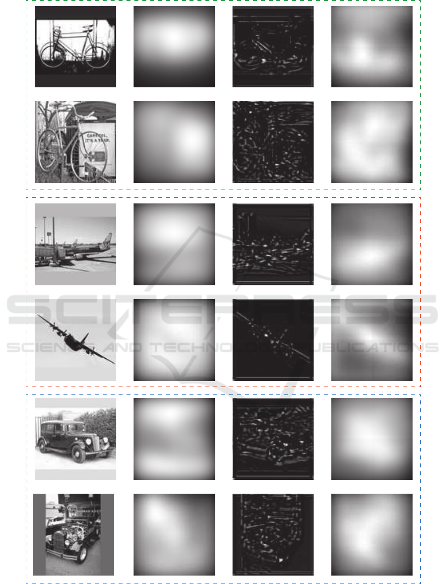
Figure 6: Exemplary results of the enhanced perceptual images of the virtual patient and unaltered virtually perceived images
for the three object classes bicycle (dashed green box), airplane (red dashed box), and car (blue dashed box). From left
to right: Original input image, perceived image without any previously applied image transformation, transformed image,
perceived image of the transformed input.
Perception Enhancement for Bionic Vision - Preliminary Study on Object Classification with Subretinal Implants
177
