
A Multi-stage Centralized Approach to Formation Flight Routing
and Assignment of Long-haul Airline Operations
Malik Doole and Hendrikus G. Visser
Faculty of Aerospace Engineering, Delft University of Technology, P.O. Box 5058, 2600 GB, Delft, Netherlands
Keywords: Formation Flight, Flight Routing, Fleet Assignment, Fuel-efficiency.
Abstract: This paper describes the development of an optimization-based multi-stage centralized planning system for
the efficient routing and assignment of extended flight formations in commercial airline operations. In an
extended formation, where aircraft are longitudinally separated by 5-40 wingspans, a trailing aircraft can
attain a reduction in induced drag at fixed lift, and consequently in fuel burn, by flying in the upwash of the
leading aircraft’s wake. To organize the assembly of flight formations on a network-wide scale essentially
two distinct approaches can be taken, viz., a centralized approach and a decentralized approach. Both
approaches have distinct advantages and disadvantages. In this study a novel multi-stage method for flight
formation assignment is proposed that combines the advantages of the decentralized approach (fast
computation and reduced vulnerability to flight delays) with the main benefit of the centralized approach (a
near-global optimum in terms of fuel savings). The multi-stage centralized approach that we propose is
validated and subsequently demonstrated in a case study involving a wave of 267 eastbound transatlantic
flights. In the case study fuel savings of 6.8% are recorded (relative to flying “solo”), while flying in
formations comprising up to 16 aircraft.
1 INTRODUCTION
Over the past decades, a variety of studies has been
devoted to exploring the use of extended formation
flight as a means to improve the fuel efficiency in
commercial aviation. In an extended formation,
where aircraft are longitudinally separated by 5-40
wingspans, a trailing aircraft can attain a reduction
in induced drag at fixed lift by flying in the upwash
of the leading aircraft’s wake (Bower et al, 2009).
Evidently, a reduction in induced drag translates
directly into a reduction in fuel burn for aircraft
trailing in a formation. An experimental study
involving a formation flight of two military C-17
transport aircraft revealed that fuel savings of 5-10%
for the trailing aircraft are possible, increasing with
mission length (Flanzer&Bieniawski, 2014).
With the drag reduction mechanism in formation
flight now relatively well understood, the focus in
research on flight formation has shifted in recent
years into the direction of the organization and
planning of flight formations of commercial aircraft
operations on an airline (alliance) network-wide
scale (Ning et al, 2014).
To organize the assembly of flight formations on
a network-wide scale essentially two distinct
approaches can be taken, viz., a centralized approach
and a decentralized approach (Visser et al, 2016). In
a centralized approach formations are determined
pre-flight through concurrent optimization of the
routing and assignment of formation flights for an
entire fleet, whilst in a decentralized (agent-based)
approach the assembly of flight formations is
conducted in-flight through local coordination of
flights. Both approaches have distinct advantages
and disadvantages. The main benefit of using a
centralized formation planning method is the ability
to provide globally optimal (fuel-saving) solutions.
However, a centralized approach is computationally
expensive compared to the fast local solutions that
are obtained via a decentralized approach, in a
realistically sized network. The huge computational
burden of a centralized approach is a direct result of
the combinatorial complexity of the associated (NP-
hard) assignment problem. Another disadvantage of
a centralized approach is that it does not readily
accommodate schedule disruptions, thus providing a
global optimum only in the absence of flight delays.
In contrast, decentralized approaches make it
Doole, M. and Visser, H.
A Multi-stage Centralized Approach to Formation Flight Routing and Assignment of Long-haul Airline Operations.
DOI: 10.5220/0006661800470058
In Proceedings of the 4th International Conference on Vehicle Technology and Intelligent Transport Systems (VEHITS 2018), pages 47-58
ISBN: 978-989-758-293-6
Copyright
c
2019 by SCITEPRESS – Science and Technology Publications, Lda. All rights reserved
47

possible to manage delayed flights by simply
searching for alternative formation flight partners.
However, decentralized approaches typically exhibit
a number of shortcomings as well, notably the sub-
optimal fuel savings due to the local nature of the
employed coordination method.
Excellent examples of a centralized approach
concern the studies presented by Kent & Richards
(2015) and by Xu et al (2014). In both studies, the
centralized approach taken to formation routing and
assignment concerns a so-called two-stage (or bi-
level) method. In the first stage, the routing/mission
problem is considered for each candidate set of two
or three long-haul origin/destination flights that
might join in, respectively, a two or three aircraft
formation. The first stage routing problem
essentially deals with locating the rendezvous and
splitting points for the flights involved in each
potential formation and with scheduling the
associated altitude/speed profiles such that the
overall mission (fuel) cost is minimized. Assessment
of the mission fuel burn is based on the Breguet-
range equation for given speed and altitude. The
second stage concerns the assignment problem, in
which the network is optimized by selecting the best
subset of formation and solo missions given the
complete set of all possible combinations of
individually optimized formation and solo missions
obtained in the first stage.
Both studies involving centralized approaches
(Kent & Richards, 2015; Xu et al, 2014) were faced
with the necessity to deal with the highly-
combinatorial assignment process, while keeping the
computational burden within check. The
combinatorial problem emerges when enumerating
the number of possible combinations of aircraft
formations for a set of n (unidirectional) O/D flights,
to be grouped into formations of size m. Therefore,
given a formation of size m and a set of n flights, the
number of possible formation combinations N
m
can
be computed from the binomial coefficient:
()
!
!!
m
n
n
N
m
mn m
==
−
(1)
The number of possible formations N
m
grows
rapidly with increasing values of either m or n. For
example, when considering a fleet size n = 500, the
number of possible formation combinations is equal
to N
m
= 124,750 for a formation size m = 2, while N
m
= 2,573,031,125 for a formation size m = 4. Since all
possible combinations need to be evaluated in the
first stage of the flight scheduling process, i.e., the
routing/mission analysis problem, it is readily clear
that introducing formations of large size renders the
scheduling problem computationally intractable. In
order to keep the computational burden in check, in
both studies (Kent & Richards, 2015; Xu et al, 2014)
flight formations up to size 3 only are considered,
while other simplifying measures have been
introduced as well. In Kent & Richards (2015) it is
proposed to partition the global lists of flights in a
number of ways (e.g. by airline or alliance) to keep n
relatively low. Moreover, a computationally efficient
geometric method for formation routing and mission
analysis is employed in the first stage, which makes
it possible to evaluate a large number of
combinations very quickly. In contrast, in Xu et al
(2014) a relatively high-fidelity, computationally
expensive routing/mission analysis is employed in
the first stage of the scheduling process; here the
computational savings are obtained through the
introduction of heuristics that allow the number of
formations to be considered in the first stage of the
scheduling process to be reduced, by filtering out all
non-viable flight formation combinations upfront.
Motivated by concerns regarding the
combinatorial complexity of the assignment of large
fleets in a centralized approach, an alternative
decentralized (agent-based) approach to the coupled
problem of formation flight routing and assignment
was conceived in (Visser et al, 2016). In this
approach formation flight is not anticipated pre-
flight but rather treated as an in-flight option based
on local coordination. More specifically, this study
implements a `proposal-marriage' type greedy-
algorithm for decentralised assignment of flights
into formations, similar to the one proposed in
(Ribichini&Frazzoli, 2003) for formation scheduling
of UAVs. However, the coupled routing and mission
analysis required for each formation combination
option is treated differently in both studies. While
the study reported in (Visser et al, 2016) relies on
the - slightly adapted - geometric formation flight
routing method as proposed by Kent & Richards
(2015), in combination with the Breguet-range
equation for fuel-burn assessment, the work in
(Ribichini&Frazzoli, 2003) implements a graph
search over possible rendezvous and splitting points
to find the optimal routing for each formation
combination, in conjunction with the assumption of
constant fuel-burn rates.
Both studies (Ribichini&Frazzoli, 2003; Visser
et al, 2016) clearly demonstrate that by resorting to
an agent-based, decentralized approach the inherent
weaknesses, notably their vulnerability to delayed
flights and the huge computational burden resulting
from the highly-combinatorial assignment process,
VEHITS 2018 - 4th International Conference on Vehicle Technology and Intelligent Transport Systems
48

can essentially be eliminated. In (Visser et al, 2016)
it is clearly shown that in the proposed decentralized
approach flight (departure) delays can be readily
accommodated, as delayed aircraft are simply able
to search alternative formation flight partners within
the network. Another beneficial feature of the
approach proposed in (Visser et al, 2016) is that it
permits building formations of (arbitrarily) large
size. This is achieved by considering two aircraft
that have just joined in a two-ship formation as a
single “entity” that then becomes eligible for further
assignment in subsequent down-route stages.
Despite its ability to overcome the typical
weaknesses of centralized approaches, there is also a
major downside associated to a decentralized
approach, in the sense that the global fuel savings
potential of flight formation is not fully achieved, due
to the greedy nature of the flight formation assembly
decision making process. Indeed, the numerical
experiments conducted in (Doole, 2016) show that the
decentralized approach presented in (Visser et al,
2016) results in fuel burn savings that are only
fraction of the global fuel burn savings potential (50
to 60% in large-scale transatlantic scenarios).
In this paper a novel method for flight formation
routing is proposed that aims to combine the advant-
ages of the decentralized approach (fast computation
and reduced vulnerability to flight delays) with the
main benefit of the centralized approach (a near-
global optimum in terms of fuel savings). The main
aim of this study is to evaluate the fuel saving
potential of this novel multi-stage centralized
approach to formation flight routing, which combines
some elements of the decentralized approach
presented in (Ribichini &Frazzoli, 2003) with the
geometric formation flight routing method as
proposed by Kent & Richards (2015) in their bi-level
centralized approach. The sections that follow provide
a problem formulation and the proposed operational
concept. Next, this paper discusses the employed
routing method along with the modelling of fuel burn.
This is then followed by a description and validation
of a multi-stage fleet assignment model. Finally, a
transatlantic case study is presented, from which the
conclusions of this paper originate.
2 OPERATIONAL CONCEPT
Inspired by (Visser et al, 2016) and (Kent &
Richards, 2015), a novel multi-stage centralized
approach has been conceived for formation routing
and assignment. The new approach that is proposed
is based on a multi-stage assignment algorithm that
updates the assignment of flight formations each
time a certain event occurs. An event in this context
is defined as: a departure, joining, or splitting of a
flight within the network. As soon as one these
events occurs, a flight formation assignment is made
involving all eligible en-route flights, while
considering the current aircraft positions as the
“origin” nodes of the flights. The key feature of the
multi-stage centralized approach is that in each
assignment stage, only formations of size two are
assembled, reducing the combinatorial complexity
of the assignment in each step.
The initial assignment evaluation is made as
soon as the first two aircraft that have departed to
their destinations (using great circle routes) reach
cruise altitude. The most likely outcome of this first
assignment evaluation is that an assembly of a flight
formation is not favourable and the two flights will
continue on their solo routes towards their
destination. As soon as the next aircraft reaches its
cruise level, a new assignment evaluation is
triggered, which includes the new flight. This
process is repeated until at a certain point, the first
two-ship flight formation is assigned. The two
aircraft involved in the formation assignment then
change course and speed so as to rendezvous at the
calculated joining point. During their transition
towards this joining point, the two flights involved
are not eligible for any subsequent assignment.
However, once these two aircraft have joined, the
resulting two-ship formation is regarded as a single
“entity” that then again becomes eligible for
assignment, thus allowing the assembly of larger
formations in subsequent assignment stages.
3 FUEL BURN ASSESSMENT
In this study we consider all aircraft operating in the
network to be of the same type The parameters of
the particular aircraft model employed in this study
relate to a Boeing B777, and have been extracted
from (Visser et al, 2016). The transatlantic routes are
modeled in this study as great circle paths from
origins to destinations. Moreover, it is assumed that
the entire route is flown in cruise at a single constant
altitude and at constant speed. The fuel consumption
along the routes is estimated using the well-known
Breguet-range equations for flight at constant
altitude and constant speed (Vinh, 1993), assuming
the absence of wind:
12
11
max
2
tan tan
md md
LL
L
DLLt
CC
C
V
R
CCCc
−−
=−
,
(2)
A Multi-stage Centralized Approach to Formation Flight Routing and Assignment of Long-haul Airline Operations
49

where :
0
2
;,1,2
1
2
md i
D
i
LL
C
W
CC i
K
VS
ρ
== =
(3)
are, respectively, the values of the lift coefficient for
minimum drag, and for the initial and final weight of
the aircraft (at the considered altitude and speed).
The parameter :
0
max
1
2
L
D
D
C
C
CK
=
(4)
in Eq.(2) represents the maximum lift over drag
ratio. The above relationships assume a traditional
drag polar of the form C
D
0
2
.
DL
CKC=+ The
parameter
t
c in Eq.(2) represents the Specific Fuel
Consumption (SFC) of the aircraft type considered.
Equation (2) can be resolved for the aircraft
weight at the end of the flight stage, W
2
, given an
initial weight W
1
:
1
11
21
2
tan
tan
md
md md
L
L
LL
LL
C
C
WW
CC
CC
ψ
ψ
−
=
+
(5)
where :
max
2
t
L
D
Rc
C
V
C
ψ
=
(6)
Alternatively, given a final weight W
2
, the required
initial weight W
1
needed to fly a distance R can be
estimated using Eq.(6). Note that Eq.(6) can be used
to assess fuel burn in both solo flight legs and
formation flight legs. To allow for the formation
drag reduction, a discounting factor λ is used in the
induced drag coefficient K of a trailing aircraft in a
formation, i.e. K
trailing
= λ K. In the present study, a
discount factor λ = 0.867 has been adopted (Visser et
al, 2016), which results in a fuel flow rate reduction
of about 10% for each trailing aircraft in a
formation. It is noted that several aerodynamic
studies related to formation flight point out that the
formation induced drag reduction increases as the
number of aircraft in the formation string increases
(Ning et al, 2014; Xue&Hornby, 2012). However, in
this study this particular effect is ignored and each
trailing aircraft in a formation essentially enjoys the
same induced drag discount factor, regardless of the
size of the formation string. Note that organizing the
traffic flow into larger formation flights can still be
very rewarding in the sense that the number of
formation flight leaders that are needed (and that
don’t enjoy any drag reduction benefit) can be
reduced in this way.
The constant speed that is adopted along a route
is generally taken as M=0.82 in this study. This
Mach number is slightly lower than the typical
cruise value for the aircraft type considered, in order
to mitigate compressibility effects in a formation
which may impede aircraft safety (Ning et al, 2014).
For reasons of simplicity, this Mach number is also
adopted in all solo flight legs, with one exception.
This exception relates to aircraft flying the shortest
flight leg towards the joining point in a formation
rendezvous. In order to rendezvous at the joining
point, the aircraft flying the shortest leg needs to
reduce its speed relative to its partner aircraft flying
the longer leg. Note that the lowest speed in a
synchronization flight leg is the maximum
endurance speed, which is the speed at which the
lowest fuel consumption per unit of time is attained
(Vinh, 1993). Assuming a drag polar as defined in
Eq.(4), the maximum endurance speed corresponds
to the speed for minimum drag and is given by :
0
1/4
2
md
D
WK
V
SC
ρ
=
(7)
The actual take-off weight for a specific (great
circle route) flight is calculated using the Breguet-
range equation assuming that at destination the
weight of the aircraft is equal to the zero-fuel weight
plus the weight of the reserve fuel. Given the aircraft
weight at destination, and the distance covered along
the route, the aircraft weight at the origin can be
assessed using the Breguet-range equation, for the
assumed speed and altitude. To allow for the fact
that aircraft may have to fly detours and thus longer
routes in order to engage in flight formation, the
initial fuel load is increased by 10%; the take-off
weight of the aircraft is increased accordingly.
4 FORMATION ROUTING
To generate routes for the assembly of formation
flights, a routing method was used based on (Kent &
Richards, 2015). In this approach, a formation flight
route for two aircraft is obtained through the
minimization of weighted distance. The time-free
routing method from Kent & Richards was extended
VEHITS 2018 - 4th International Conference on Vehicle Technology and Intelligent Transport Systems
50

in (Visser et al, 2016) to ensure rendezvous of timed
flights in the formation assembly process.
4.1 Geometric Routing Method by
Kent & Richards
In (Kent & Richards, 2015), a simple geometric
method to construct a formation flight routing is
presented based on a classical mathematical problem
posed by Fermat in the 17
th
century. The problem,
illustrated in Figure 1, is posed as follows: given a
triangle ABC (Fig.1.a), find a point P such the that
the sum of the distances
|| ||
A
P
,
|| ||BP
and
|| ||CP
is minimized. The geometric approach to
construct the solution to this problem is illustrated in
Fig.1.b.
The method shown in Fig.1.b is based on
constructing outwardly three equilateral triangles
along the sides AB, BC and CA. Then the lines from
the outer vertex of each new triangle to its opposite
vertex of the original will intersect at a single point,
which is the desired point P. Equivalently, the point
P can be found as the intersection point of the
circumscribed circles of each of the three new
equilateral triangles.
Fermat’s problem provides a good analogy to
the formation flight assembly problem, if it is
assumed that fuel consumption is proportional to the
distance covered. However, it is readily clear that
the fuel consumption per unit distance along the solo
arcs
|| ||
A
P
and
|| ||
B
P
differs from that on the
formation flight arc
|| ||
P
C
. To resolve this issue,
Kent & Richards formulated a weighted-arc version
of the problem, where the arc weights reflect the
different fuel consumption per unit distance. More
specifically, to represent the cost of flying a unit of
distance, the arc weights w
A
, w
B
, and w
C
are
introduced for the segments AP, BP and PC,
respectively. Note that the value of w
C
is typically
set equal to the combined values of w
A
and w
B
, while
applying some discount factor to represent the fuel
savings due to induced drag reduction of the trailing
aircraft.
Thus, in the modified problem the location of
the joining point P has to be selected such that the
total cost of distance, expressed by Eq.(1) is
minimized:
:
( ) || || || || || ||
ABC
Minimize
P
f
PwAPwBPwPC=⋅ +⋅ +⋅
(8)
Following Kent & Richards, the location of point P
that minimizes Eq.(9) must satisfy the vectorial
equilibrium condition expressed by Eq.(2):
0||
|| || || || || ||
ABC
AP BP PC
www
AP BP PC
⋅+⋅+⋅ =
(9)
(a) (b)
Figure 1: Geometric construction to locate the optimal
joining point P (Kent & Richards, 2015).
Application of the law of cosines to Eq.(9) yields
expressions for the intersection angles ∠APB,
∠APC, and ∠BPC. Since the angle ∠APB represents
the intersection angle between the two solo legs AP
and BP, it is referred to as the “formation angle”.
Equation (10) gives the expression for the resulting
formation angle
θ
f
:
222
1
cos |
2
ABC
f
AB
www
ww
θ
−
−− +
=
(10)
Note that the formation angle
θ
f
only depends on the
routing weights w
A
, w
B
, and w
C
. The formation angle
is illustrated in Figure 2. It is noted that as long as
the weights w
A
, w
B
, and w
C
are not altered, also the
formation angle
θ
f
remains unaffected. As a result,
the point C can be shifted freely along the line PC,
without altering the solution.
Figure 2: Illustration of formation angle.
The method for locating point P can be extended to a
scenario in which the two flights do not have a
common destination C. Figure 4 illustrates two solo
A Multi-stage Centralized Approach to Formation Flight Routing and Assignment of Long-haul Airline Operations
51
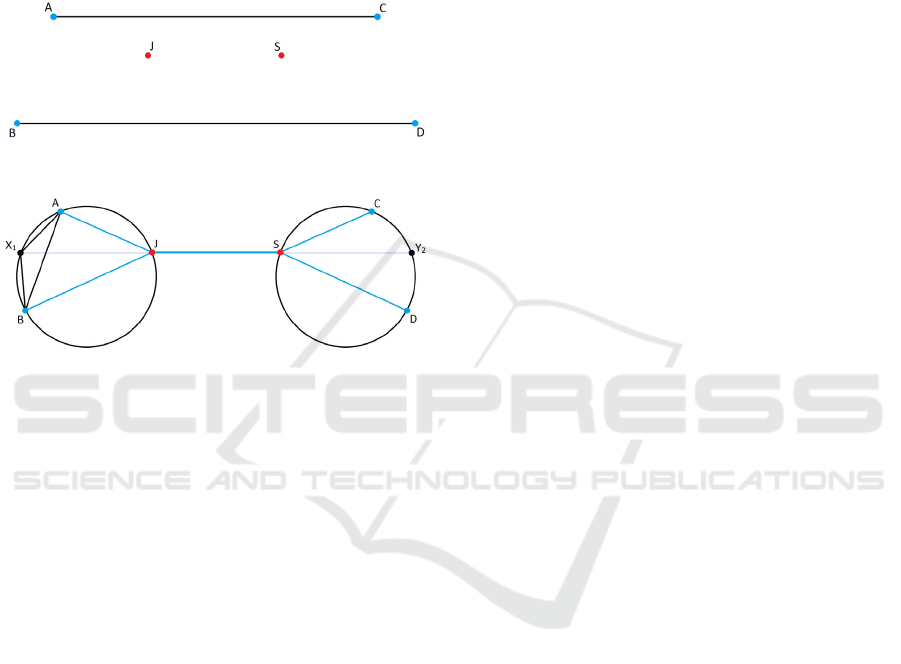
routes connecting origins A and B to destinations C
and D, respectively. The joining point J and the
splitting point S are to be determined. Since the
formation angle condition must be satisfied at both J
and S in order to minimize the weighted distance,
one can draw two circular arcs from A to B and from
C to D along which the formation angle is constant
and equal to the value obtained from Eq.(11). These
arcs are displayed in Figure 4.
Figure 3: Illustration of example solo routes AC and BD.
Figure 4: Geometric construction of the formation route.
The (back vertex) point X
1
in Fig. 4 is obtained by
making use of the fact that Eq.(11) holds in triangle
ABX
1
:
11
||:| |:| | ::|
CAB
A
BBX XAwww= (11)
Mirroring the described steps at the destinations C
and D provides the (back vertex) point Y
2
. The
locations of J and S that minimize the weighted
distance from A to C and from B to D are obtained
from the intersections of the line from X
1
to Y
2
and
the arcs of constant formation angle.
4.2 Accommodating Synchronization in
the Basic Routing Method
The geometric routing procedure presented in
Section 4.1 is inherently time-free, essentially
assuming that the flight schedules are synchronized
such that the two flights joining in formation are
able to rendezvous at the calculated joining point.
However, the approach proposed herein considers
flight formation to be an in-flight option, with the
current aircraft positions serving as the origin nodes
of the flights. Therefore, in order to realize
formation flight, the route must be constructed such
that the two aircraft are able to arrive at the joining
point simultaneously. For solo flight legs to the
joining point that are not too dissimilar in size,
synchronization is typically accomplished by
slightly slowing down the aircraft that is flying the
shortest leg. However, if the formation flight route
does not permit synchronization in this way, the
joining point must be relocated to enable a stretch of
the connecting flight legs. It is conceivable that even
relocating the joining point may not be sufficient to
ensure a rendezvous. In this case, excess delay time
needs to be absorbed by holding one of the aircraft
at the joining point. When the latter situation occurs,
usually the formation option turns out to be less
favorable then flying solo. Details regarding the
synchronization process can be found in (Visser et
al, 2016).
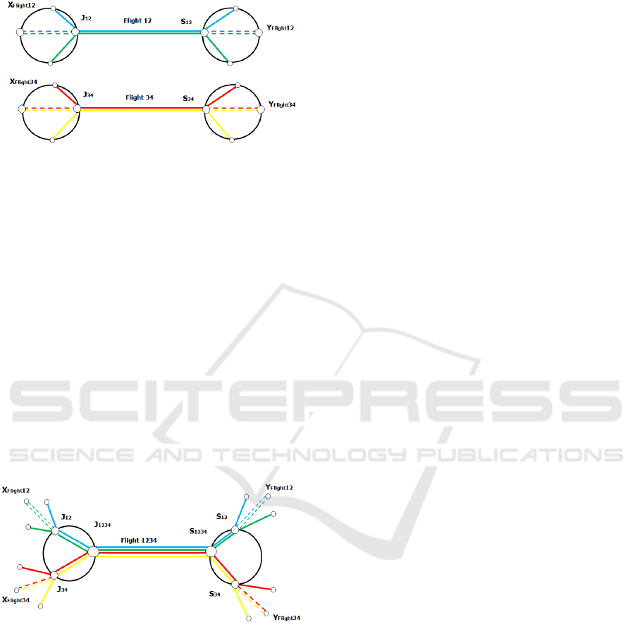
4.3 An Extension to Larger Formation
Sizes
Kent&Richards (2015) demonstrated that the
geometric routing approach developed for the
assembly of two-ship formations could be extended
to formations of any size. Here, we will illustrate
this extension for the assembly of a four-ship flight
formation. Figure 5.a shows the assembly of two
two-ship formations; in the first two-ship formation
Flights 1 and 2 are joined, while in the second two-
ship formation Flights 3 and 4 are joined. These
two-ship formations are now regarded as two
“pseudo flights” (respectively, Flight
12
and Flight
34
),
with, respectively, the back vertices
12
flight
X and
34
flight
X
serving as origin nodes and the back vertices
12
flight
Y
and
34
flight
Y
as destination nodes. Next, as
shown in Fig.6 the two pseudo flights Flight
12
and
Flight
34
join in formation, and a joining and splitting
point are computed in the same way as for the
assembly of a two-ship formation. The resulting
four-ship formation can then then regarded as a new
pseudo flight (Flight
1234
). It is noted that the four-
ship formation assembly sketched in Fig.6 presumes
a certain order of joining in formation (e.g., Flight 1
first joins with Flight 2) and therefore represents just
one of the options in the four-ship formation
assembly process for these four flights. All
alternative joining order options (e.g., Flight 1 first
joins with Flight 3, or Flight 1 first joins with Flight
4) need to be explored as well, including the
possibility of three-ship formations (pseudo flights)
joining with single aircraft flights. It is readily clear
that the assembly of larger formations represents is
also problem that is highly combinatorial in nature.
In (Doole, 2016) the time-free four-ship assembly
VEHITS 2018 - 4th International Conference on Vehicle Technology and Intelligent Transport Systems
52
process proposed by Kent & Richards has been
extended to include flight synchronization.
Figure 5: Assembly of two two-ship formations (pseudo
flights, Flight
12
and Flight
34
) from four solo flights.
4.4 Formation Leaders
When two, or more, flights have successfully
completed their rendezvous, one of the aircraft
involved needs to be assigned as the formation
leader. A flight that does not lead a formation, is
referred to as a ‘trailing’. In the present set-up,
where only aircraft of the same type are considered,
it is readily clear what the best choice is from a
collective perspective: the least heavy aircraft of the
two is designated as the lead aircraft, as the heavy
aircraft can benefit relative more from an induced
drag reduction. It is noted that the formation leader
does not gain any direct benefit from flying in an
extended formation; however, in this study it is
assumed that formation partners will somehow share
the overall economic benefits.
Figure 6: Assembly of a four-ship formations (pseudo
flight, Flight
1234
) from two two-ship formations.
4.5 Azimuthal Equidistant Projection
Method
The geometric approach presented herein is
inherently planar in nature, however it can be
extended to hold for problems on a sphere (Kent &
Richards, 2015). This latter option has not been
pursued in this study; rather the great circle routes
connecting the various O/D pairs were projected on
a plane by means of the so-called azimuthal
equidistant projection method (Tobler, 1962), so that
the original planar geometric approach can be
retained. The azimuthal equidistant projection
method has the property that all distances from the
center are rendered correctly to scale and that all
points on the map are at the correct azimuth
(direction) from the center point. By using this
particular projection method, the relative locations
of the origins and destinations, as well as the route
lengths and relative flight headings remain
reasonably well preserved in the transformation.
Since these route characteristics are most relevant
for the success of formation flight implementation,
the selected projection method is considered
appropriate for this study.
5 FLEET ASSIGNMENT
PROBLEM
5.1 Basic BMILP Formulation
The fleet assignment model that has been adopted
selects a compatible set of possible flight formations
in order to achieve global minimum fuel burn. The
optimization problem used to solve the formation
flight assignment is formulated as a Binary Mixed-
Integer Linear Program (BMILP), using a similar
formulation as adopted by Kent & Richards (2015).
Given a fleet of size n = N, and flight
formations up to size m = M (including solo flights,
which are regarded as flight formations of size one),
the total possible number of flight formations N
F
is
given by:
1
(, ) ()
mM
Fm
m
NNM N N
=
=
=
, (12)
where N
m
is the binomial coefficient defined in
Eq.(1) that gives the number of possible formation
combinations of size m. To give an example,
suppose we have a fleet of N = 5 aircraft and we
consider formations up to size M = 3, we then have:
1
5N = ;
2
10N = ;
3
10N = ;
4
5N = ;
5
1N = ,
and thus N
F
(5,3) = N
1
+ N
2
+ N
3
+ N
4
+ N
5
= 31
possible formation combinations are found.
The variables and (cost and pairing) coefficients
that are used to define the fleet assignment problem
are as follows:
x
j
A binary decision variable that has the value
one if configuration j is selected in the
solution and zero otherwise.
c
j
A real-valued cost coefficient that represents
the total incurred fuel cost of formation j.
A Multi-stage Centralized Approach to Formation Flight Routing and Assignment of Long-haul Airline Operations
53

p
ij
A binary pairing coefficient that indicates
whether flight i is included in formation j
(p
ij
= 1) or not (p
ij
= 0).
The BMILP formulation that is used to optimally
assign each flight to a formation is then given by :
minimize
1
F
jN
j
j
j
J
cx
=
=
=⋅
, (13)
subject to :
{
}
1
1 , 1,...,
F
jN
ij j
j
px i N
=
=
⋅= ∀∈
(14)
{
}
1
, 1,...,
0
j
F
x
jN
=∀∈
(15)
The number of binary variables is equal to the
number of possible flight formations N
F
, which
increases dramatically with the number of flights N,
and especially with the maximum formation string
size M. It is readily clear that for larger problems (in
terms of maximum formation string size M), the
combinatorial complexity of the MILP becomes
significant and a huge computational effort is
required. In the multi-stage centralized assignment
approach the number of decision variables is kept
low in each assignment step basically by restricting
the formation string size to just two. In this case the
number of potential formation combinations
amounts to:
2
(1)
2
NN
N
−
=
(16)
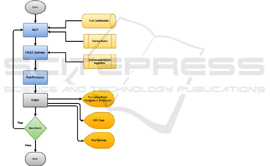
5.2 Multi-Stage Fleet Assignment
Model
Figure 7 presents a schematic diagram of the
developed multi-stage fleet assignment model. A
new assignment is made every time an event (i.e., a
departure, joining, or splitting) occurs. When an
event takes place, the location of each eligible flight
(or pseudo flight) that is en-route is determined and
subsequently all potential flight formation missions
for the eligible fleet are assessed in terms of routing
and fuel burn performance, and the associated cost
and pairing coefficients are determined. Next, the
BMILP problem is formulated and solved (using
CPLEX) and the resulting formations are assigned;
the aircraft (strings) involved in the assignment are
declared ineligible for further assignment until they
have joined. Note that when such a joining takes
place a new event is triggered.
6 VALIDATION OF THE
MULTI-STAGE FLEET
ASSIGNMENT MODEL
To prove the effectiveness and efficiency of the
proposed multi-stage centralized approach to flight
formation routing and assignment a validation study
was undertaken. In this validation study the
(computational and fuel burn) performance of the
newly developed multi-stage fleet assignment
approach is compared against that of the original bi-
level centralized approach of Kent & Richards
(2015), albeit that both approaches are somewhat
modified in order to provide a proper basis of
comparison. More specifically, since the centralized
approach of Kent & Richards is essentially time-
free, it has been augmented with the rendezvous
synchronization mechanism for formation flight
routing developed in (Visser et al, 2016), so that it
can be used in conjunction with a given flight
schedule. Since the centralized approach of Kent &
Richards is computationally expensive for large
problems, a relatively small fleet assignment
problem is considered in the validation scenario.
More specifically, in the validation scenario the
assignment problem is limited to formations
comprising strings up to four aircraft (M = 4) only,
whilst considering a fleet of 50 aircraft (N = 50) that
seek to traverse the North Atlantic. Even for this
relatively small problem, the enumeration time is
significant as the number of potential formations is
already quite large. Using Eq.(1), it is readily
established that there are 1,225 two-ship, 19,600
three-ship, and 230,300 four-ship formation
combination possibilities, in addition to the 50 solo
flights. Therefore, aside from the 50 solo flights,
there are 251,125 possible formation combinations
in total, each requiring individual formation routing
and fuel burn predictions. It is recalled that the
routing/mission analysis itself is also plagued by
combinatorial complexity issues, leading to
computational times that increase dramatically with
the maximum size of the formation string.
The multi-stage fleet assignment model
developed herein is run in a “degraded” mode of
operation in the validation scenario. In order to
avoid the assembly of formations in excess of size
four, an assignment step is not made after each
occurrence of an event, but rather in just two
discrete stages. First of all, in the validation scenario
it is assumed that all 50 flights depart at exactly the
same time; at this given departure time the first
assignment evaluation is made. A second assignment
VEHITS 2018 - 4th International Conference on Vehicle Technology and Intelligent Transport Systems
54
step is then made as soon as all formations that were
assigned in the first stage have actually joined up.
Evidently, in the first stage only formations up to
size two can emerge, while in the second stage
formations up to size four can be assembled.
Clearly, in the first stage there are only 1,225
possible (two-ship) flight formations, in addition to
the 50 solo flights. In the second assignment stage,
the “fleet” to be considered is substantially smaller
than in the first stage. The reason for this is that it
turns out that in the first stage 24 two-ship
formations were assembled (involving 48 aircraft),
so that in the second stage the fleet only comprises
24 “pseudo flights” and 2 solo flights, for a total of
26 entities. The total number of possible formations
in the second stage (for formations ranging from size
1 up to size 4) is therefore just 302.
Figure 7: Flow chart of the operational multi-stage fleet
assignment concept.
The performance characteristics of both
assignment approaches are summarized in Table 1.
The centralized approach by Kent&Richards (2015)
is denoted here as the “single-stage” approach,
whilst the multi-stage fleet assignment approach
proposed herein is labeled as the “two-stage”
approach. In Table 1, the number of potential
formation combinations (and thus routing/mission
analysis evaluations) that is assessed in each
approach is indicated, along with the required CPU
time (on a standard 2.1 GHz personal computer),
and the resulting fuel savings of formation flight in
absolute terms and in relative terms (as compared to
executing all flights solo).
A close inspection of the results in Table 1
reveals that the two-stage approach performs almost
equally well as the single-stage approach in terms of
fuel savings, but at only a fraction of the
computational cost. Overall, the differences in the
routing and assignment solutions between the two
approaches turn out to be marginal.
7 TRANSATLANTIC CASE
STUDY
The proposed multi-stage fleet assignment model is
applied in a case study involving 267 eastbound
transatlantic flights. It is assumed in this case study
that each flight can potentially join in formation with
any other flight in the network (regardless of airline
or alliance membership). The routes included in the
case study, shown in Figure 8, are obtained from an
available real-life data set (Lith et al, 2014) by
means of selecting the longitude/latitude coordinates
of all origins and destinations. However, in order to
make the case study more challenging, it is assumed
that all 267 flights depart at the same time.
Also in the transatlantic case study, an alternative
fleet assignment approach is considered to obtain a
basis of comparison for the multi-stage centralized
approach. Given the size of the assignment problem,
the agent-based decentralized approach reported in
(Visser et al, 2016) is applied in the case study to
provide the basis for comparison.
In the simulation of the decentralized formation
flight planning method a local search for potential
partners is conducted once every 5 minutes. The
employed communication radius for formation
assembly negotiation is set at 250 km; hence only
flights within this radius are considered eligible for
formation assembly.
The results for the decentralized approach bear
out that the largest observed formation is a sixteen-
ship formation. To establish a fair basis of
comparison, a restriction on the maximum size of a
formation is enforced in the multi-stage centralized
approach as well, in the sense that no formations is
excess of size 16 are allowed to be assembled. To
this end, the multi-stage assignment model is again
run in “degraded mode”, limiting the assignment
updates to just four discrete stages.
c
j
p
ij
A Multi-stage Centralized Approach to Formation Flight Routing and Assignment of Long-haul Airline Operations
55
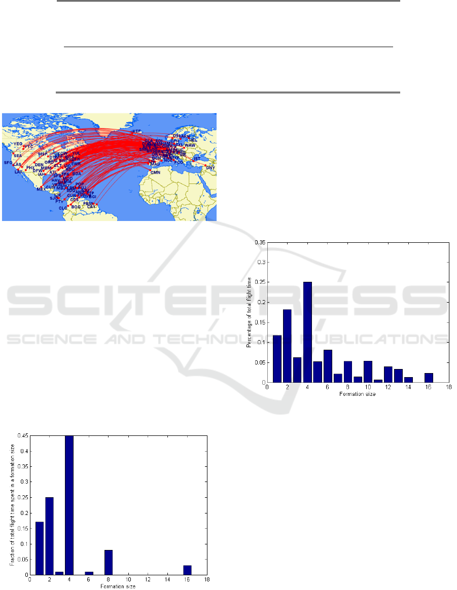
Table 1: Performance comparison between single-stage and two-stage fleet assignment solutions.
Approach Formation
combinations
Computation
time (mm:ss)
Fuel savings
(%)
Fuel saved
(kg)
Single-Stage 251,175 58:43 5.72 184,381
Two-Stage 1,577 00:14 5.66 182,480
Figure 8: Route set used in the case study (created using
Great Circle Mapper at www.gcmap.com).
The results for the multi-stage assignment model
are summarized in Figure 9, which shows the
fraction of total time spent in formations ranging in
size 1 to size 16. It is readily clear that the majority
of the time is spent in formations of size 4. Indeed,
no less than 58 four-ship formations are assembled
in this transatlantic case study, half of which later
merge into larger formations. Although ultimately
four sixteen-ship formations are assembled, the total
time spent in these largest formations is relatively
small. No formations of size 5 or 7 were assembled.
Moreover, the sixteen-ship formations are the only
formations in excess of size 8. Only two flights do
not engage in flight formation and remain solo. It is
Figure 9: Formation size usage when the multi-stage fleet
assignment approach is employed.
noted that the results might be somewhat tainted by
the fact that the multi-stage fleet assignment model
has been run in “degraded mode”. This will be
explored in future research.
Figure 10 shows the corresponding results for the
agent-based decentralized approach. It can be seen
that in the decentralized approach considerably less
time is spent in formations of size four. Moreover, a
wider variety in the size of the formations that are
formed is observed.
Figure 10: Formation size usage when the decentralized
fleet assignment approach is employed.
In Table 2 the computational and fuel burn
performances of the two approaches are compared.
When comparing the results, it is evident that the
multi-stage centralized approach is vastly superior is
terms of fuel savings. Indeed, the savings in the
multi-stage centralized approach are almost twice
that of the decentralize approach. Although the total
computational time for the multi-stage approach
features a significantly higher computational burden
relative to the decentralized approach, in absolute
terms the computational time is still modest and
remains well within the requirement for real-time
application.
VEHITS 2018 - 4th International Conference on Vehicle Technology and Intelligent Transport Systems
56

Table 2: Performance comparison between multi-stage centralized and decentralized assignment solutions.
Approach
Computation
time (mm:ss)
Fuel savings
(%)
Fuel saved
(kg)
Multi-stage Centralized
Decentralized
09:24 6.88 1,202,000
03:23 3.90 681,200
8 CONCLUSIONS
This study proposes a multi-stage centralized
cooperative planning system for the efficient routing
and scheduling of flight formations. In the proposed
concept, the global fleet assignment is updated every
time a certain event occurs en-route, where an event
is either the emergence of a new flight, the
emergence of a newly assembled formation, or the
emergence of a disassembly of a formation. In each
assignment update, only the assembly of formations
involving two flights are considered, where a flight
can either be an actual solo flight or a “pseudo
flight”, representing a prior assembled formation. By
limiting the formation size to just two (pseudo)
flights in each assignment step, the combinatorial
complexity of the overall assignment process can be
kept in check.
In a validation scenario involving flight
formations up to size four, it was demonstrated that
the proposed multi-stage fleet assignment model is
capable of generating a near-optimal global solution,
at a fraction of the computational cost required for
the single-stage assignment of formations up to size
four. In a subsequent large-scale transatlantic
scenario, it was demonstrated that the multi-stage
fleet assignment offers a vast improvement over a
decentralized approach in terms of the fuel savings
that can be achieved.
In view of the results obtained in this study, the
proposed concept holds out great promise for further
development towards real-world application. In
future studies, many of the simplifying assumptions
taken in the present study will need to be removed
for this purpose. In particular, the no-wind
assumption that underlies the current study has a
profound impact on the solution behavior and more
realistic wind scenarios will need to be considered in
lieu of the no-wind assumption in future studies.
Although in an extended formation aircraft fly at
safer separation distances than in close formation
flight, aircraft still fly in relatively close proximity,
exceeding current regulated separation minima.
Many aviation regulations and standards, including
the reduction of aircraft separation limits, therefore
will need to be adapted. The technical, operational
and regulatory challenges associated to introducing
extended formation in the civil aviation domain need
to be investigated in future research.
REFERENCES
Bower, G. C., Flanzer, T.C. and Kroo, I., 2009. Formation
Geometries and Route Optimization for Commercial
Formation Flight. In: Proc. AIAA Applied
Aerodynamics Conf., 22 - 25 June 2009, San Antonio,
TX, USA
Doole, M., 2016. Multi-Stage Formation Flight Planning.
MSc thesis, TU Delft, Delft, The Netherlands.
Flanzer, T. C. and Bieniawski, S. R., 2014. Operational
Analysis for the Formation Flight for Aerodynamic
Benefit Program. In: Proc. AIAA Aerospace Sciences
Meeting, 13 - 17 January 2014, National Harbor, MD,
USA.
Kent, T. E. and Richards, A. G., 2015. Optimal,
environmentally-friendly departure procedures for
civil aircraft. Journal of Guidance, Control, and
Dynamics, Vol.38, No.10, pp.1872-1884.
Lith, M. M. van, Visser, H. G, Hosseini, S. H., 2014.
Modelling an Operations Concept for Commercial
Air-to-Air Refueling Based on a Vehicle Routing
Problem Formulation. In: Proc. of the 29th ICAS
Congress, September 7 - 12 2014, St. Petersburg,
Russia.
Ning, S. A., Kroo, I., Aftosmis, M. J., Nemec, M. and
Kless, J.E., 2014. Extended Formation Flight at
Transonic Speeds. Journal of Aircraft, Vol.51, No.5,
pp. 1501-1510.
Ribichini, G. and Frazzoli, E., 2003. Energy-Efficient
Coordination of Multiple-UAV systems In: Proc.
AIAA Guidance, Navigation, and Control Conf., 11-
14 August 2003, Austin, TX, USA.
Tobler, W. R., 1962. A Classification of Map Projections.
Annals of the Association of American Geographer,
Vol.52, pp. 167-175.
A Multi-stage Centralized Approach to Formation Flight Routing and Assignment of Long-haul Airline Operations
57

Vinh, N. X., 1993. Flight Mechanics of High-Performance
Aircraft. Cambridge University Press, Cambridge,
U.K.
Visser, H. G., Santos, B. F. and Verhagen, C. M. A., 2016.
A Decentralized Approach to Formation Flight
Routing. In: Proc. ATRS World Conf., 23 - 26 June
2016, Rhodes, Greece.
Xu, J, Ning, S. A., Bower, G. and Kroo, I., 2014. Aircraft
Route Optimization for Formation Flight. Journal of
Aircraft, Vol.51, No.2, pp.490-501.
Xue, M., and Hornby, G. S., 2012. An Analysis of the
Potential Savings from Using Formation Flight in the
NAS. In: Proc. AIAA Guidance, Navigation, and
Control Conf., 13-16 August 2012, Minneapolis, MN,
USA.
VEHITS 2018 - 4th International Conference on Vehicle Technology and Intelligent Transport Systems
58
