
Fully Virtual Rapid ADAS Prototyping via
a Joined Multi-domain Co-simulation Ecosystem
R´obert Lajos B¨ucs, Pramod Lakshman, Jan Henrik Weinstock,
Florian Walbroel, Rainer Leup ers and Gerd Ascheid
Institute for Communication Technologies and Embedded Systems, RWTH Aachen University, Germany
Keywords:
ADAS Prototyping, Driving Simulators, Virtual Platforms, Multi-domain S imulation, Near Real-time
Execution.
Abstract:
Advanced Driver Assistance Systems (ADAS) have evolved into comprehensive hardware/software applicati-
ons with explodi ng complexity. Various simulation-driven techniques emerged to facilitate their development,
e.g., model-based design and driving simulators. However, these approaches are mostly restricted to functional
prototyping only. Virtual platform technology is a promising solution to overcome this limitation by accura-
tely simulating the entir e ADAS hardware/software stack, including functional and non-functional properties.
However, al l these tools and techniques are limited to their individual simulation environments. To reap their
combined benefits, this paper proposes a joined frameworking to facilitate ADAS prototyping via full vir-
tualization and whole-system simulation. For this purpose, an advanced automotive-flavor virtual platform
was also designed, ensuring detailed, near real-time simulation. The benefits of the approach and the joined
frameworks are shown by prototyping two ADAS applications in various system configurations.
1 INTRODUCTION
Vehicles have evolved from mainly mechanical to
complex hardware (HW) and software (SW) driven
systems in the last deca des. Vehicular SW covers vast
areas, ranging from infotainment, over safety-critical
control tasks, heading all together toward s highly au-
tomated driving. Furthermore, recent HW trends re-
flect strong integration, i.e., fewer Electronic Cont-
rol Units (ECUs) with multi and many-c ore CPUs.
The resulting architecture of Advanced Driver Assis-
tance Systems (ADAS) consist o f up to 100 networ-
ked ECUs with 250 embedded and grap hic processors
(Georgakos et al., 2013), executing an estimated 100
million lines of code (Charette, 2009).
Moreover, frequent factory recalls have been ob-
served in the past years in case of various ma nufac-
turers, most of which were caused by failures in the
electronic system (NHTSA, 2017). This called a tten-
tion to secure HW/SW design, test and validation for
which the automotive industry agreed on functional
safety standards, e .g., the (ISO 26262, 2011). The
standard defines strict rules to ensure functional safety
throughout the complete lifecycle of the HW/SW sy-
stem and recommends full-system simulation to pro-
vide early guarantees for this purpose. However, with
the sheer com plexity of the electronic and electri-
cal system and the demanding requir ements posed by
functional safety standards, ADAS development and
validation has become immensely difficult.
Model-Based Design (MBD): Utilizing MBD
tools is advised to tackle these cha llenges, offering
early algorithmic prototypin g, in-tool testin g and of-
ten ISO-certified code generation. MBD tools accele-
rate the d esign-validation-refinement cycle of ADAS
via a simulation-driven appr oach. Yet, MBD tools are
limited to (i) rigid artificial inputs and outputs (I/O)
and (ii) model only algorithmic aspects of ADAS.
Driving Simulators: Such frameworks address
the first limitation of MBD tools by providing realis-
tic I/O via their virtual driving environment. This ena-
bles ADAS evaluation/refinement via virtual test dri-
ves, while experimenting with various traffic and en-
vironm ental conditions and vehicle types (e.g., cars,
trucks). Moreover, driving simulators ensure deter-
ministic test repeatability, which is crucial if spurious
errors occu r. They can also include a driver in the
ADAS evaluation, thus capturing real human reacti-
ons. Yet, driving simulators are restricted to model
only functional aspects of ADAS. Moreover, they are
limited to their simulation environmen t, making a joi-
ned usage with further tools mostly unfeasible.
Bücs, R., Lakshman, P., Weinstock, J., Walbroel, F., Leupers, R. and Ascheid, G.
Fully Virtual Rapid ADAS Prototyping via a Joined Multi-domain Co-simulation Ecosystem.
DOI: 10.5220/0006665900590069
In Proceedings of the 4th International Conference on Vehicle Technology and Intelligent Transport Systems (VEHITS 2018), pages 59-69
ISBN: 978-989-758-293-6
Copyright
c
2019 by SCITEPRESS – Science and Technology Publications, Lda. All rights reserved
59

Virtua l Platforms (VPs): This technology ad-
dresses the seco nd limitation of MBD too ls by ex-
tending the simulation to the ADAS HW/SW system.
VPs consist of simulation models of HW b locks and
their interconnection, created via electr onic system-
level standards, e.g., SystemC/TLM (Accelera, 2012).
These enable modeling and simulation of full sy-
stems including, e.g., CPUs, buses, memor ie s and
various peripheral devices. Moreover, V Ps enable
HW/SW co-design by simulating the whole ADAS
SW layer as executed by the platform. Conversely to
MBD tools, VPs enable exploring non-functional sy-
stem properties, e.g., HW/SW partitioning, task map-
ping, schedulability and dynamic worst-case execu-
tion time analysis. VPs also facilitate system pro-
totyping by providing full HW/SW visibility, debug-
gability and non-intrusive mo nitoring, while ensuring
execution determinism. However, VPs are generally
limited by either their simulation speeds or modeling
accuracy. Moreover, similarly to driving simulators,
VPs are limited beyond their simulation environment.
Multi-Domain Co-Simulation: This technique
extends the boundaries of specialized simulation tools
and models by providing mea ns for cross-do main in-
terconne ction and joined contr ol. The multi-domain
approa c h can be used to fulfill the ISO 26262 requi-
rement of full-sy stem valid ation by co-simulating va-
rious vehicular subsystems. This would allow to con-
nect the HW/SW simu lation with the virtual env iron-
ment of a driving simulator. Too l-agnostic standar ds
are defined for such purposes, overcoming the inflex-
ibility of point-to-point connections. However, tar-
get tools/models have to be ma de compliant to multi-
domain co-simulation stand ards for joined utilizatio n.
Objectives: To reap their combined benefits, this
paper prop oses joining the preceding tools and tec hni-
ques to facilitate and accelerate ADAS prototyping
via full virtualization and whole-system simulation.
Putting this in prac tice, a joined frameworking is pre-
sented, composed by carefully chosen tools and stan-
dards, addressing the previous limitations, as follows:
# 1. Overcoming the ar tificial I/O limitation of MBD
tools by using the environment of driving simulators.
# 2. Extending the functional simulation capability
of MBD tools and driving simulators by ensuring
beyond functional modeling and exploratio n via VPs.
# 3. Providing compliance for all target tools to a se-
lected m ulti-domain co- simulation standard.
# 4. Addressing the speed/accu racy tra de-off of VPs
via an advanced automotive-flavor platform that en-
sures detailed and fast simulation at the same time.
# 5. Pursuing near real-time whole-system co-
simulation execution, to be able to involve the
developer in the virtual ADAS test driving process.
The propo sed frameworking allows ADAS testing
in a closed-loop, i.e., (i) capturing the environment
of a driving simulator via virtual sensors (ii) input-
ting th e gathered data and executing the target ADAS
on a VP and (iii) applying regula tory actions on the
virtual vehicle within the driving simulator. Lastly, to
highlight its advantages, two ADAS applications were
prototy ped usin g the proposed full-sy stem simulator.
2 BACKGROUND
The previously p resented ideas pose strict require-
ments on simulation ecosystems. Thus, various tools
and standards were carefully compared to select the
most suitable combination fulfilling the prerequisites.
In this work, Simulink (MathWorks, 2017) was
chosen as M BD tool in the ADAS design automation
flow, as it provides advanced modeling semantics, a
vast block set and in-tool simulation features. Moreo-
ver, its certified code generato r ensures safe and con-
tinuous ADAS integration onto target HW devices.
The requirements for a driving simulator in the
proposed approach are availability, adaptability and a
realistic virtual driving environment. After care fully
examining numerous driving simulators, an open-
source r acing game, Sp eed Dreams 2 (SD2, 2017),
was selected as it supports various traffic and envi-
ronmental conditions (e.g., precipitation, visibility),
different ca r types and configurable vehicle dynamics
(e.g., component dimensions). In this work, the tool
was extended with urban traffic simulation support
and ADAS virtual test driving in such environments.
Lastly, compliance to a selected multi-domain co-
simulation stan dard was also added, ensuring con-
nectivity beyond its simulation environment.
The v irtual platform technology is concerned with
the strictest requirements in the proposed methodo-
logy and has been the main focus of this work. The
envisioned framewo rk needs to accurately model and
simulate the complete ADAS HW/SW stack. On the
HW side, this requires assemb ling a scalable distri-
buted system, consisting of a configurable number of
modular subsy stems connected over a vehicular com-
munication bus. Moreover, the envisioned platform
needs to execute the complete ADA S SW stack, inclu-
ding the target algorithms, and ideally a f ull-fledged
automotive Operating System (OS).
Due to its magnitude and complexity, the VP is
expected to be the p e rformance bottleneck of the
whole fram eworking. Thus, to avoid slowing down
the full-system simulation, the platform needs to
achieve execution speeds close to real-tim e. Conside-
ring these serious r equirements, numerous SystemC-
VEHITS 2018 - 4th International Conference on Vehicle Technology and Intelligent Transport Systems
60

based simulation technologies were carefully exami-
ned. From these, th e GreenSoCs (GreenSoCs, 2017)
framework emerged as the best choice. At its heart,
GreenSoCs uses the QEMU (Bellard, 2005) fast emu-
lation technology to overcome the strongest perfor-
mance bottleneck o f a VP, the CPU mo del. In this
regard, QEMU can be also configured to contain mul-
tiple instances of the CPU module in a single package,
still maintaining high execution efficiency. Its per-
formance lies in the just-in-time compilation engine,
translating and caching target CPU instructions to
code blocks of the simulation host at run-time. Ho-
weve r, due to the natu re of sy stem emulation, QEMU
completely lacks timing annotation, which degrades
the overall simulation accuracy. To address this issue,
the GreenSoCs technology provides a dedicated Sy-
stemC wrapper around QEMU, thus integrating the
CPU models into the timed SystemC environment.
Herewith, GreenSoCs-based platform s can leverage
both, fast simulation and temporal accuracy at CPU
instruction level. The necessary timing management
is achieved by synchronizing the global simula tion
time whenever QEMU is a head of the current Sys-
temC time by more than an amount called quantum.
Based on GreenSoCs, this work pre sents an ad-
vanced automotive-flavor VP that supports distributed
multi-core setups while maintaining high execution
efficiency, as detailed later. Lastly, to ensure connecti-
vity beyond its environment, the VP has been made
compliant to a multi-domain c o-simulation standard.
In this regard, various standards were compa-
red to join the previously presented distinct simula-
tion ecosystems by co-simulating arbitrary vehicular
subsystems beyo nd tool and domain boundaries. A
centralized orchestration was envisioned for joined
co-simulation control. After thorough examination,
the Functional Mock-up Interface (FMI, 2017) was
selected, a light-weight, open-source, tool-agnostic
specification, considered the de facto multi-domain
co-simulation standard for automotive applicatio ns.
FMI defines a master/slave approach, where a centra l
master is respo nsible for sy nchron iz ation and data ex-
change between multiple slaves. Although the stan-
dard states the respo nsibilities of the master, it does
not propose a reference implementation. In this work
an in-house FMI master has been utilized for orches-
tration, as it ac hieve s hig hly efficient co-simulation
execution by implementing a parallel control engine.
On the other hand, FMI slaves, or Functional
Mock-up Units (FMUs), encapsulate target to ols/-
models following the light-weight FMI C-API. This
prescribes FMUs to implement functions for model
creation/de le tion (e.g.,
fmi2Instantiate()
), run-
control (e. g.,
fmi2DoStep()
) and data excha nge
(e.g.,
fmi2Get/Set()
), among others. The resulting
FMUs are bundles containing (i) the model imple-
mentation (e.g., source code, pre-compiled binary)
(ii) a de scription file definin g its external interface ( iii)
other resources (e. g., third- party tools, do cuments).
Lastly, this work presents a generic method to ens-
ure compliance of domain-spe cific simulation tools to
FMI. The resulting co-simulation system allows cou-
pling arbitrary FMUs to it, thus overcoming the in-
flexibility of direct, point-to-p oint connections.
3 JOINED MULTI-DOMAIN
SIMULAT ION SYSTEM FOR
RAPID ADAS PROTOTYPING
The selected simulation ecosystems are promising
high-performa nce base technolog ie s for the envisio-
ned whole-system simulator. This section presents
details to their adaptation to establish a fully virtual
ADAS rapid prototyp ing environment. The r esulting
framework system is described step by step next.
3.1 Generic FMI-based Tool-coupling
First, an FMI-based, generic coupling technique was
designed for the target simulators and models. The
FMI standard defines two possible conn e ction opti-
ons for FMUs: standalone or tool-coupling. The for-
mer FMUs are self- contained, including the model,
the simulator an d all run-time dependencies. Conver-
sely, tool-coupling FMUs are simple communication
adapters, inter acting with a simulator that contains the
target model. Although standalon e FMUs are more
straight-fo rward to imp le ment, research indicates se-
vere pro blems with multiple instantiatio n and library
co-dep e ndencies (B¨ucs et al., 2015). Thus, in this
work the tool-coupling technique was favored, as it
separates the adap te r and the target simulator into iso-
lated processes, which is a more reasonable approach
for the envisioned fra mewo rking.
Depicted in Fig.1, first a Generic FMI Tool-
Coupling Adapter was designed for this pur pose. For
simplicity, the adap ter was constructed as a standa-
lone FMU. Thus, the FMI m a ster can load the mo-
dule directly (without further dependencies) into its
own host OS process. At instantiation, the adap-
ter pr e pares an inter-process communication chan-
nel for interacting with a target simulation tool. So
that the adapter rema ins ind ependen t from sim ula-
tors and can be reused for arbitrary subsystems, a
user-layer comma nd protocol was defined (inspired
by (GDB, 2017)), named FMI Inter-proc ess commu-
Fully Virtual Rapid ADAS Prototyping via a Joined Multi-domain Co-simulation Ecosystem
61
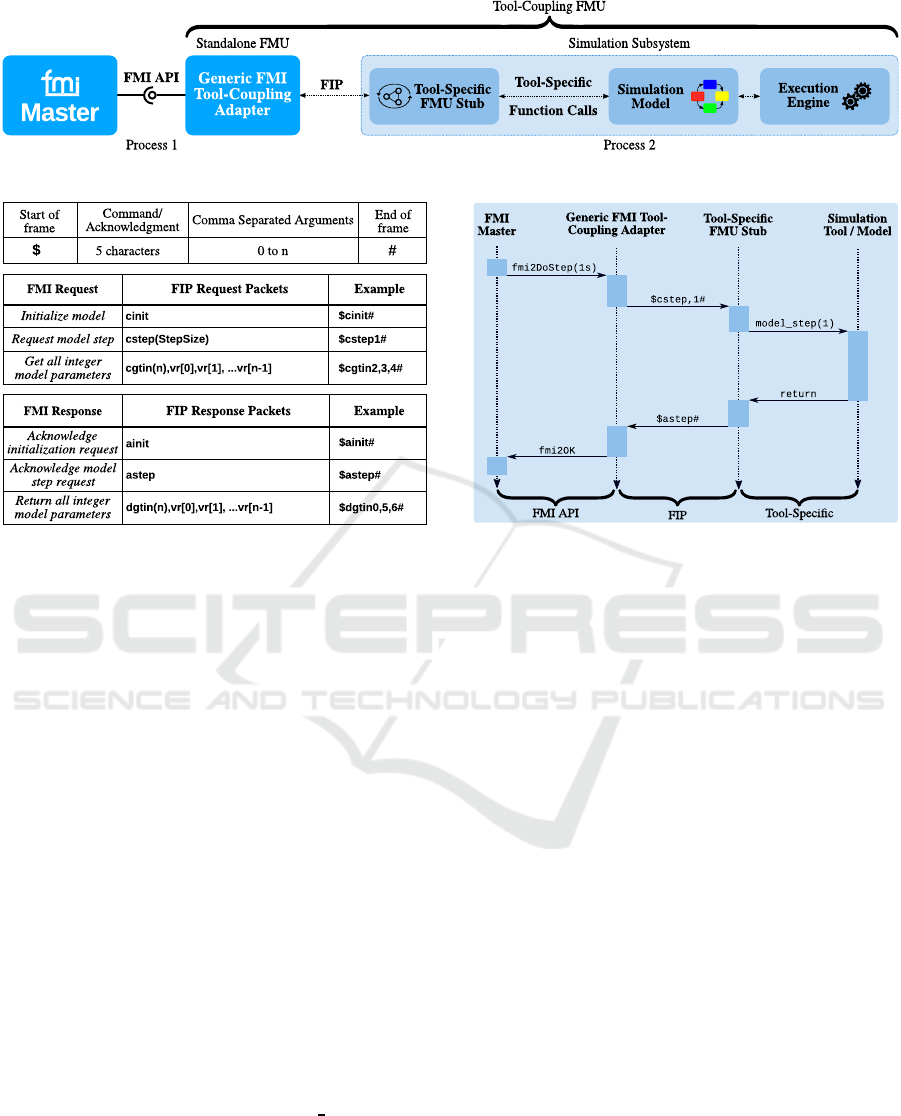
Figure 1: Generic FMI-based tool-coupling layer.
Figure 2: Examples of FMI function to FIP frame mapping.
nication Pro tocol (FIP). This implements a remote
proced ure call mechanism, where FMI API functi-
ons are translated to commands / acknowledgments
of FIP, as exemplified in Fig.2. Herein , first the frame
format can be observed, including the packet deli-
miters $ and
#
. Below, several example s of FMI
function to FIP frame mappings are demonstrated for
various requests and responses. For instance, the
fmi2DoStep()
API function with t
step
= 1 s trans-
lates to the FIP message $
cstep1#
and later to the
acknowledgment $
astep#
, sent to the FMI master.
On the other side of the interaction, individual,
Tool-Specific FMU Stubs need to be d e signed, that
receive the FIP package s and execute the initial FMI
request on the target model, as shown in Fig.1. To cla-
rify the complete communication mechanism, Fig.3
depicts a sequence diagram. Follow ing up on the
previous example, the FMI master invokes again the
fmi2DoStep()
API function with t
step
= 1 s. This
call is translated to the FIP comma nd
cstep
by the
Generic FMI Tool-Coupling Adapter and sent to the
Tool-Specific FMU Stub. The packet is then interpre-
ted, and a tool-specific function call is invoked by the
stub, in this me ta -code example
model step()
. Af-
ter completing the mode l step, the stub sends the ma-
tching acknowledgment
astep
to the adapter, which
passes the call status to the master.
The FIP-based adapter-stub m echanism addresses
the #3 objective of this work (Sec.1), providing a ge-
neric app roach for target tools to comply to FMI. The
Figure 3: Sequence diagram of FIP-based communication.
correspo nding tool extensions are presented next.
3.2 Adaptation of Speed Dreams 2
As mentioned previously, the or iginal SD2 racing
game was extended within the scope of this work to
support urban tra ffic simulation and ADAS virtual test
drives. First, city and c ountry-side maps were cre-
ated, and support for two-lane roads, intersections,
two-way traffic and buildings was added, as depicted
in Fig.4. Fur thermore, the robots were adapted to fol-
low traffic regulations, e.g., speed limits a nd yield the
right of way, which is crucial in intersections.
Next, SD2 was converted into a tool-coupling
FMU based on the mech anisms detailed in Sec.3.1.
Shown in Fig.4, first a tool-specific Speed Dreams
2 FMU Stub was created to process FIP commands,
sent by the FMI master over the adapter. The stub
executes con trol operations via the Simulation Run-
Control modu le, includin g stepping vehicle dynamics
calculations. The stub can also access and expose pa-
rameters of the driving sim ulator, required for da ta ex-
change with other FMUs. Herein a Parameter A c cess
module was built, granting safe data access for pro-
perties of Ve hicle Dynamics and the Virtu al Driving
Environment, as indicated in the figure.
These adaptations address the #1 and #3 objecti-
ves of this work (Sec.1). First, the virtual environ-
ment of the driving simulator overcomes the limita-
tion of artificial I/O. Moreover, the FMU c ompliance
VEHITS 2018 - 4th International Conference on Vehicle Technology and Intelligent Transport Systems
62
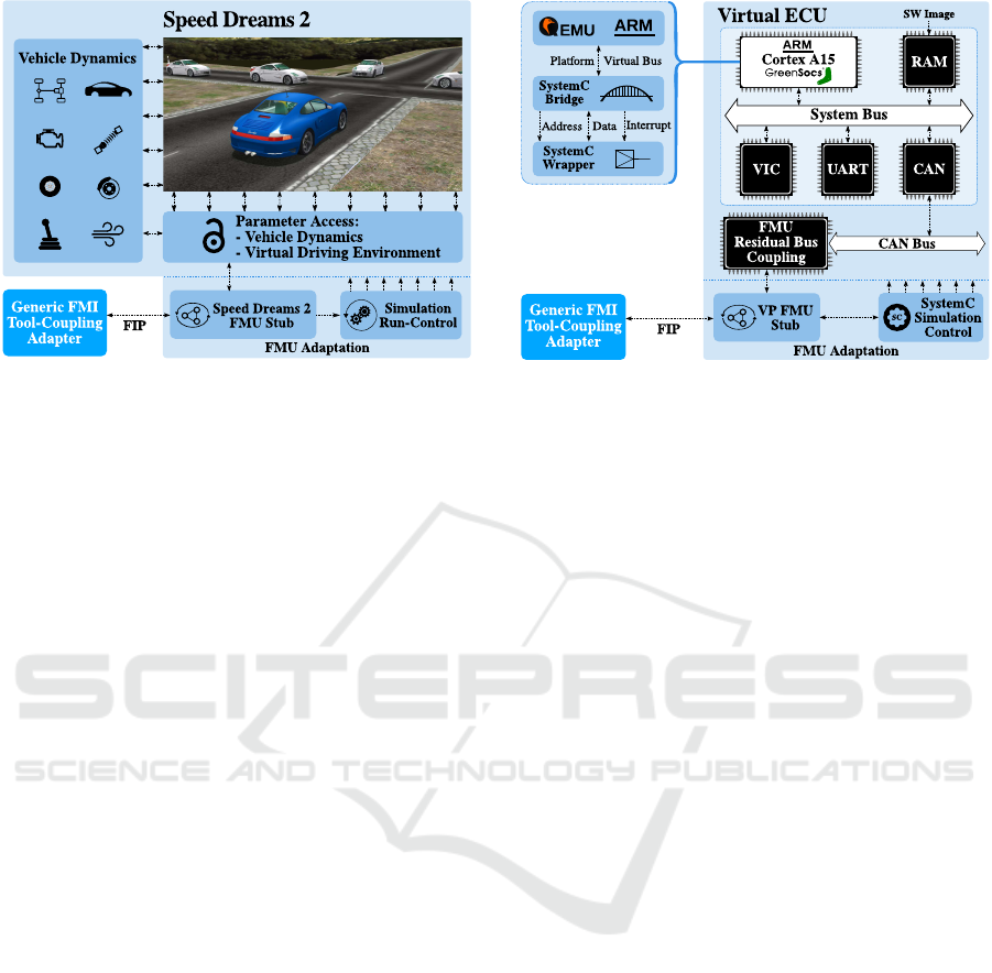
Figure 4: Block diagram of the modified SD2 simulator.
allows for external connections and control, requi-
red for m ulti-domain co-simulation. These tra its can
be exploited to achieve A DAS modeling beyond the
functional level by utilizing a VP, detailed next.
3.3 Automotive Virtual Platform Design
Following the strict requirements discussed in Sec.2,
an automotive -flavor VP was designed to extend the
scope of ADAS testing. Shown in Fig.5, the VP con-
sists of virtual ECUs (vECUs), modeling a modified
ARM Versatile baseboard (ARM, 2017). At the he-
art of such vECUs a hig h-performance GreenSoCs-
based ARM Cortex-A15 CPU model (ARM, 2012)
is embedded. Depicted in Fig.5 , this module con-
sist of (i) the QEMU-based ARM processor simulator,
(ii) a SystemC Bridge, capturing acc ess commands
of QEMU’s Platform Virtual Bus, converting them to
SystemC transactions/signals (e.g., address, data, in-
terrupt) and (iii) a SystemC Wrapper, encapsulating
the whole package as a SystemC module, providing
all defined model interfaces (e.g., TLM sockets).
Furthermore, vECUs contain various in-house de-
signed peripheral devices, e.g., an on- c hip memory,
a system bus, serial communication modules (UART)
and a Vectored Interrupt Controller (VIC), among ot-
hers. The particula r set of HW peripherals and virtual
devices was chosen so that vECUs are ab le to exe-
cute full-fledged OSs. Moreover, the platform archi-
tecture was designed to be scalable by instantiatin g
a configurable number of interconne cted vECUs, so
to resemble a distributed multi-core system. Hence,
each vECU was also equipped with a Controller Area
Network (CAN) transceiver for inter-vECU comm u-
nication over a single CAN-bus, as shown in Fig.5.
After its c onstruction, the platform was converted
into a tool-coupling FMU (recalling Sec.3 .1). Simi-
larly as for the driving simulator, first a VP FMU Stub
Figure 5: Block diagram excerpt of the proposed VP.
was created to process FIP commands. Depicted in
Fig.5, the stub also executes control opera tions via the
SystemC Simulation Control component, which is re-
sponsible for creation/deletion of SystemC m odules
and run-state control. To expose the internal HW/SW
state towards the co-simulation, an FMU Residual
Bus Coupling unit was designed, acting as a bridge
between SystemC and FMI. This module is capable
of buffering/updating certain user-selec te d messages
via their unique CAN identifiers as they a re transmit-
ted over the CAN bus. Eac h of these can correspond
to specific HW/SW parameters (e.g., SW variables,
HW signals). If the FMI master requires reading a
parameter, a lookup is performed in the buffer for the
correspo nding CAN identifier, and the message is fe-
tched, decod e d an d interpreted. Conversely, when the
master sends data to the VP, the buffer embeds the pa-
rameter into a CAN message a nd injects it to the bus.
However, initial VP performance tests shown a
notable simulation slowdow n in multi-core setups, li-
nearly with the number of adde d CPU models. As this
issue contradic ted the scalability an d performance
requirements, a more e ffective simulation tech no-
logy was required alongside the Green SoCs approach.
Thus, the idea arose to exploit the inherent parallelism
of the VP due to its modular structure. This resul-
ted in executing each CPU model on a separate host
thread and the remaining peripherals of the vECU on
another, as they are less performance-critical. The re-
sulting parallel segments run decoupled, ahead of the
global simulation time, but are synchronized whene-
ver their own local time reaches the quantum (recal-
ling Sec.2). Platform parallelization achieves major
performance gains, reaching execution speeds beyond
real-time, as presented later.
The resulting performance-optimized VP addres-
ses the #2-#5 objectives of this work (Sec.1). Fir-
stly, it extends the simulation spectrum to the ADAS
Fully Virtual Rapid ADAS Prototyping via a Joined Multi-domain Co-simulation Ecosystem
63
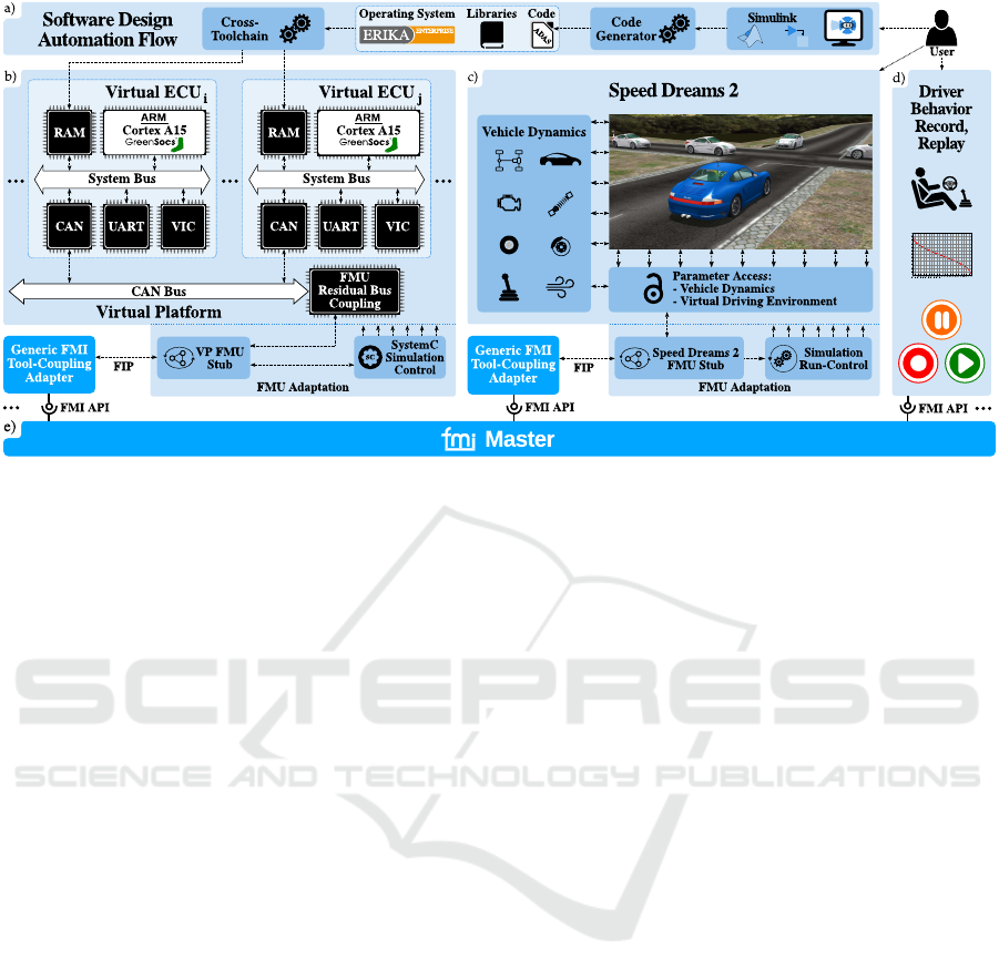
Figure 6: Joined framework system, co-simulation interconnection and design automation flow for rapid ADAS prototyping.
HW/SW system , covering analysis of non-func tional
properties (e.g., HW/SW partitioning). Moreover,
the FMU adaptation allows for external connection s
and control, required for mu lti- domain co-simulation.
Lastly, the presented performa nce improvements ad-
dress the speed/accuracy trade-off and the pursuit for
near real-time whole-system execution.
3.4 The Virtual Platform SW Stack
Next, the SW layers were designed for integrating
ADAS pro totypes as embedded code onto the crea-
ted VP. At first, the integration can be performed in
form of bare-metal SW. For this purp ose, base SW
components were created, consisting of low-level uti-
lities (e.g., cross-toolchain, linker script, bootloader),
a standard C librar y and a driver layer for the peripher-
als. The bare-metal setup enables early functional va-
lidation of ADAS properties, as well as HW/SW de-
sign space exploration, partitioning and distribution.
However, safety-critical ADAS applications have
far stricter requirements, e.g., har d real-time execu-
tion guara ntees a nd HW/SW protection mechanisms.
To manage such ap plications, the au tomotive indu-
stry laid down Real-Time Operating System (RTOS)
standards, such as OSEK/VDX (OSEK Group, 20 05)
and its successor AUTOSAR (AUTOSAR, 2014).
Both impose portability of SW components, priority-
based multi-task ing, standard commun ic ation layers,
safe resource management and real-time scheduling,
among others. Since AUTOSAR implementations
were not available at the point this work was con-
ducted, OSEK/VDX was chosen instead. Herein se-
veral variants were examined, and ERIKA Enterprise
(EE) (Ev idence, 2017) was selected among them, a
comprehensive, open-source OSEK/VDX implemen -
tation with full tool support. EE is especially favored
in open-source RTOS-based research activities, since
it is developed towards the AUTOSAR specification.
In this work, EE was ported to the designed
VP following the guidelines outlined in (Evidence,
2014). Herein various mechanisms were adapted,
e.g., for fixed-priority scheduling, nested interrupt
(IRQ) handling and inter-task communication beyond
vECUs. However, since all details would go beyond
the boundaries of this work, a full description of the
porting instructions can be found in (Eviden c e, 20 14).
3.5 The Full Design Automation Flow
After having all subsystems in place, the joined fra-
meworking can be used as follows. Shown in Fig.6a,
Simulink is the starting point for ADAS development
and early functional testing. Once a prototype is ma-
ture enough, Simulink’s built-in code generator can
be invoked to obtain embedded code for it. The re-
sulting ADA S C-modules can first be integrated o nto
the VP as bare-metal SW for ea rly functional valida-
tion and HW/SW design space exploratio n. To sup-
port this, the VP can be configured to include as many
vECUs a s desired for the current development stage
(Fig.6b). Moreover, SW integration and validation is
supported by the possibility of run-time debugging on
the VP, as the GreenSoCs tech nology allows attach ing
SW debuggers to the virtual CPU models. In more
mature development stages, ADAS applications can
be integrated as EE tasks onto the VP for refine ment
of non-functional properties, e.g., execution times and
VEHITS 2018 - 4th International Conference on Vehicle Technology and Intelligent Transport Systems
64
Algorithm 1: LKA optimal steer angle control.
Input: w
road
:road width [m], w
lane
:lane width [m], ∢
veh
abs
:vehicle-road
angle [rad], θ
rel
:segment-relative yaw [rad], lane:ongoing/incoming
Output: ∢
steer
: steer angle
// Update current and optimal vehicle position in lane
1: d
le f t
← get dist from left(...)
2: d
right
← get
dist from right(...)
3: d
opt
← w
lane
/2
// Get target lane for the LKA to operate in
4: if lane == ongoing then
5: d
di f f
← d
right
- d
opt
6: else
7: d
di f f
← d
opt
- d
le f t
// Correct steer angle
∢
steer
8: ∢
steer
← ∢
veh
abs
+ θ
rel
− d
opt
/w
road
// Normalize
∢
steer
to
−Π...Π
9: while ∢
steer
> Π do
10: ∢
steer
← ∢
steer
− 2 ∗ Π
11: while ∢
steer
< −Π do
12: ∢
steer
← ∢
steer
+ 2 ∗ Π
and scheduling. For all such design iteration s, a full
co-simulation can be set up via the FMI master, lo-
ading the tool-coupling FMUs of the VP and SD2
(Fig.6e). In th is setup, the user can engage virtual
test driving in SD2, while the target ADAS is execu-
ted on the VP, regulating the behavior of the virtual
vehicle. In case of spuriously occurring errors, a Dri-
ver Beh avior Record/Replay FMU was added to the
co-simulation (Fig.6d), so to ensure exact test repea-
tability. The most notable feature of the presented sy-
stem in terms of productivity is that it can achieve the
complete ADAS exploration cycle (adjustment, code
generation/integration, test drive) in minutes. To pre-
sent its detailed capabilities, two driver assistance ap-
plications were prototyped with its help, as presented
next.
4 RAPID ADAS PROTOTYPING
This section presents the refinement process of the
created ADAS ben c hmarks. It must be noted that the
focus here is not on the designed ADAS itself, but on
the capability of the assembled f rameworking to ex -
plore system properties on various abstra c tion levels.
4.1 Lane Keep Assistant (LKA)
This ADAS performs a closed-loop steering control
of the veh ic le, positioning it inside the driving lane.
The LKA was designed for two operating mo des, (i)
automatically keeping the mid-point of the lane (ii)
actively avoiding lane de parture, while the driver is
Figure 7: Flow chart of the automatic transmission control.
still mainly in c ontrol. Algorithm 1 presents a meta-
code description of the former mod e. Herein, first the
road and lane width s are used to calculate th e opti-
mal and actual vehicle positions in the driving road-
way (lines 1-3). Next, according to the selection of
the incoming/ongoing lane, the distance error is cal-
culated (lines 4-7). Subsequently, the steer angle is
corrected using the current vehicle-road ang le and the
segment-relative yaw to compensate the distance er-
ror (line 8). The segment-relative yaw is defined as
the rotational movement along the axis which is per-
pendicu la r to the chassis plane. This value is compu-
ted as the angular difference b etween the x-y plane of
the car chassis coordin ate system and the x-y plane of
the road segment within the world coordin a te system.
Lastly, the updated steer angle is normalized to the
range {∢
steer
∈ R | − Π ≤ ∢
steer
≤ Π}.
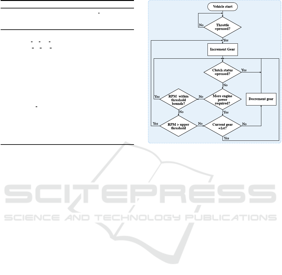
4.2 Automatic Transmission Control
(ATC)
This algorithm was created as a closed-loop, finite
state machine, periodically providing the gear contr ol
output afte r evaluating its inputs: the e ngine speed,
the state of the virtua l clutch release sensor and the
user throttle control. The ATC supports various use-
cases, e.g., regular up and downshift with respect to
the current engine speed, vehicle start / stop and over-
take assistance, shif ting one gear down once it is re-
cognized that more engine power is required. The
operation of the automatic tran sm ission con trol is best
described by a flow chart, as depicted in Fig.7:
Fully Virtual Rapid ADAS Prototyping via a Joined Multi-domain Co-simulation Ecosystem
65
SC
A
Both ADAS integrated on 1x vECU as bare-metal SW.
SC
B
Both ADAS integrated on 1x vECU as EE tasks.
SC
C
Two ADAS separated on 2x vECUs as bare-metal SW.
SC
D
Two ADAS separated on 2x vECUs as EE tasks.
Figure 8: VP system setup used for benchmarking.
0 1 2 3 4
5 6
7 8 9 10 11 12 13 14
15
1.5
2.0
2.5
3.0
3.5
4.0
4.5
Time [s]
Lane Position [m]
SC
A
SC
B
Figure 10: LKA lane position in various SCs.
0 1 2 3 4
5 6
7 8 9 10 11 12 13 14
15
−20
−10
0
10
Time [s]
Steer signal [%]
SC
A
SC
B
Figure 12: LKA steer output in various SCs.
0
25 50
BT
LKA
ATC
1000
1025
System Time [µs]
Figure 14: EE task execution times measured in SC
B
.
1. From the initial vehicle start condition, the gear is
incremente d upon changes in the user throttle input.
2. Next, the clutch status is evaluated. If the vehicle
is in the m iddle of a transmission, the algorithm enters
a wait state until the clutch is released again, allowing
for further possible gear cha nges.
3. The n, additional engine power request is checked.
If the engine speed is lower but the user throttle cont-
rol higher than certain predefined thresholds, th e gear
value is decremented so to provide more power, e.g.,
in a vehicle takeover scenario.
4. Lastly, the engine speed is evaluated with r e spect
to predefined upper and lower thresholds. If the en-
gine speed remains within these bound s, the algo-
rithm enters a wait state, else an increment or decre-
ment of the g e ar value is performed accordingly. He-
rein a final check is performed to avoid unrequested
switching to natural ge ar.
SW \ HW
1x vECU 2x vECU
Bare-metal SC
A
SC
C
EE task SC
B
SC
D
Figure 9: Stage transitions of HW/SW system design.
0 1 2 3 4
5 6
7 8 9 10 11 12
2000
3000
4000
5000
6000
Time [s]
Engine Speed [RPM]
SC
A
SC
B
SC
C
SC
D
Figure 11: ATC engine speed in various SCs.
0 1 2 3 4
5 6
7 8 9 10 11 12
0
1
2
3
4
Time [s]
Gear Number [#]
SC
A
SC
B
SC
C
SC
D
Figure 13: ATC gear control in various SCs.
0 1 2 3 4
5 6
7 8 9 10 11 12
0
20
40
60
80
100
Time [s]
Clutch signal [%]
Figure 15: ATC clutch oscillation error discovered i n SC
A
.
4.3 HW/SW System Configurations
Both ADAS were integrated on the VP in the System
Configurations (SCs) shown in Fig.8. The correspon-
ding transitions in sy stem design stages are detailed in
Fig.9. This order was established to continuou sly ex-
plore and refine new HW/SW properties by lowering
the de sig n abstraction level as follows:
1. SC
A
: algorithmic prototyping and in tegra tion
2. SC
B
: timing analysis, RTOS support, inter-task comm.
3. SC
C
: refining spatial distribution
4. SC
D
: adding standard inter-vECU communication
The novelty of the fr ameworking is to enable such
a design space exploration of non-functional tr a its
(e.g., timing behavior, HW/SW partitioning), while
stepwise refining the level of system abstraction.
VEHITS 2018 - 4th International Conference on Vehicle Technology and Intelligent Transport Systems
66

100
500
1000
1500
2000
0
30
60
90
120
150
33.5
62.5
82
108.3
119
10
21
27.4
28.7
29.8
31.7
34.5
42.2
58.6
62.9
12.2
15.2
15.6
15.8
17.3
46.3
57
59.8
92.3
100
12.7
25.1
27.2
28.1
28.3
Quantum Time [µs]
Speed of CPU Models [MIPS]
SC
A
SC
B
SC
C
: ATC on virtual ECU
1
SC
D
: ATC on virtual ECU
1
SC
C
: LKA on virtual ECU
2
SC
D
: LKA on virtual ECU
2
Figure 16: Execution speeds of the CPU model(s) within the VP, using various quantum settings, measured in various SCs.
4.4 Functional and Temporal Analysis
Numerous co-simulation runs
1
were executed in the
setup shown in Fig.6 for ADAS test and refinement.
All of these were orchestrated by the FMI master ap-
plying a fixed step size of 2 ms on every subsystem.
First, signals of the LKA were captured. Fig.10
shows the lan e position of the test vehicle around the
optimum mid-point of 2.5 m. The resulting steer co n-
trol is shown in Fig.12, where negative values indicate
right, positive values left steering. The reaction of the
LKA in auto mode can be observed between 1.5-3.5 s
in a sharp r ight, and between 9.5-15 s in a longer left
curve. Only minor differences can be noted in bo th
plots betwe en SC
A
vs. SC
B
which can be explained
by the short execution time of the ADAS. Thus, even
as EE task, less system events (e.g ., IRQs) disturb its
execution. Data was also gathered in SC
C
and SC
D
,
but as only minor changes were noted (due to CAN
messages transmit times), the re sults are not shown.
More variance was found refining the ATC. Fig.11
depicts the engine speed between 1-5 s while steadily
accelerating, and between 5-12 s while alternating the
throttle. The resulting ge a r control is shown in Fig.13.
Functional and temporal deviations can be noted in
both plots. As before, the minor timing differences
between SC
A
vs. SC
C
and SC
B
vs. SC
D
are caused
by CAN message delays induced by distribution. Yet,
bare-metal vs. EE task implementation s (SC
A,C
vs.
SC
B,D
) vary strongly, causing even extra gear shifts
(around 9 s). The reason is that in SC
A,C
gear control
occurs more frequently, triggered by ad hoc activa-
tions via CAN message IRQs. Conversely, the refi-
nements of SC
B,D
grant a scheduler-based execution
with activations at discrete time stamps. Although
this occurs less often in the current setup, it provides
real-time execution guarantees, th a t SC
A,C
lack.
Moreover, Fig.15 shows the captured clutch sig-
nal, where an unexpected oscillation was observed be-
1
Simulation host: 6x AMD Phenom II 1100T x86
64,
f
clk
=3.3 GHz, 64K L1D and L1I, 512K L2 and 6144K L3
caches, 12 GB RAM, using Scientific Linux 6.8.
tween 6.5-9.2 s. Herein an algorithmic error was iden-
tified, violating a mandatory wait time between gear
shifts, foun d and correc ted by attaching a debugger to
the vECU. T his finding further affirms the a dvantages
of the co-simulation system for ADAS prototyping.
Lastly, ADAS execution times were measured in
SC
B
. Herein tasks were assigned fixed priorities from
highest to lowest as follows: ATC, LKA a nd the idle
background task (BT). As shown in Fig.14, EE sche-
dules the tasks with the period of 1 ms, following their
priorities. Moreover, the runtimes of both ADAS can
be observed: around 2 µs for the AT C and 8 µs for the
LKA. Herein, the ATC require d less time to finish as it
was in a wait state, checking only for the expiration of
the mandatory stay in gear time. Although no timing
violations were detected due to the relatively short
application run times, the measurements demonstrated
the potential of the proposed f rameworking to provide
dynamic execution time and schedulability analyses.
4.5 Co-simulation Performance
Evaluation
After profiling the co-simulation system, the VP was
found to be the main performance bottleneck. To ana-
lyze its impact, the number of executed Million In-
structions Per Second (M IPS) was captured for all
CPU models, shown in Fig.16. To quantify the speed
of the full VP, the Real-Time Factor (RTF) was used,
i.e., wall-clock time divided by simulated time, where
RTF≤1 corresponds to real-time. As the CPU mo-
dels were clocked at f
clk
=100 MH z , the goal was that
they reach 100 MIPS (RTF=1). To achieve this, the
quantum was also inc reased, with the trade-off of lo-
sing accuracy. Here it must be noted, that even higher
quanta did not cause disturbances in OS scheduling.
As shown in Fig.16, bare-metal vs. EE-based SCs
achieve higher pe rformance (SC
A
vs. SC
B
and SC
C
vs. SC
D
), as the OS induces extra events (e.g., IRQs)
causing simulation overhead. Fig.16 also indicates
that multi- vECU setups are less efficient than single-
vECU ones (SC
C
vs. SC
A
and SC
D
vs. SC
B
), as the
Fully Virtual Rapid ADAS Prototyping via a Joined Multi-domain Co-simulation Ecosystem
67

Table 1: Achieved co-simulation speeds in various SCs.
System Configuration
SC
A
SC
B
SC
C
SC
D
Average Co-Simulation
Execution Speed [FPS]
31.7 14.49 19.06 7.63
simulation effort scales linearly with added v ECUs
but parallel efficiency does not. In SC
C
and SC
D
it
can also b e seen that the vECU executing the LKA is
faster than the one running the ATC. This is explained
by the relatively simple implementation of the L KA ,
leading to faster runs and more simulation idle time.
Lastly, the efficiency of the full system (Fig.6)
was evaluated, with the quantum set to the overall
co-simulation step size of 2 ms. The ave rage Frames
Per Second (FPS) rendered by the SD2 graphic engine
was chosen as measure , as it reflects the real-time be-
havior of the full simulator. Table 1 holds the achie-
ved results. As the VP dominates the whole system
efficiency, the same trends can be no te d as for the VP
with regards to various system configurations.
Summary: Sec.4.4 highlights the poten tials of the
frameworking for system exploration and validation
of functional and non-functional ADAS traits. The re-
sults in Sec.4.5 indicate that the co -simulation system
can include the developer in virtual test driving. He-
rein certain setups (e.g., SC
A,C
) reach near real-time
whole-system execution, as frame rates over 20 FPS
are co nsidered adequa te for human p e rception. This
final achievement covers the #5 objective of the paper,
thus accomplishing all predefined goa ls.
5 RELATED WORK
Several approaches emerged for simulation-driven
ADAS design by joining distinct tools and techniques.
The authors of (Schneider and Frimberger, 2014)
present an FMI-based co-simulation framework, joi-
ning a driving environment with a purely functiona l
ADAS simulator to develop a dynamic headlight a d-
justment unit. Herein the HW/SW simulation was ab-
stracted away by static test benches, excluding closed-
loop ADAS testing and n on-functional evaluation.
To bridge this gap, authors of (B¨ucs et al., 2015)
present tec hniques to couple SystemC-based HW/SW
simulators with FMI. Although the work covers many
aspects of HW exploration and ADAS design automa-
tion, the rudimentary vehicle models used for evalua-
tion strongly limit test capabilities. Moreover, ben c h-
marking implies RTF=22. 4 for VP execution, making
it im possible to include the developer in test driving.
Authors of (Weh ner and G¨ohringer, 2013) pro-
totype an adaptive cruise control via a X ilinx Zynq
VP (Cadence, 2012) and a driving simulator. Herein
the used VP is constraine d by not allowing to cre-
ate multiple platform instances, required for distribu-
ted setups. Authors also recognize that the used em-
bedded Linux la cks real-time guarantees needed by
safety-critical ADAS. As the VP achieves RTF=5.3, it
heavily limits interactive ADAS test driving. Lastly,
an ad hoc coupling is used between the subsystems,
restraining the scalability of the simulation system.
Authors of (Raffa¨elli et al., 2016) use a joined si-
mulation framework to validate a lane departure war-
ning and an emergency brake system. They couple a
driving simulator over a test automation server with
a fast QEMU-based VP, name d Rabbits (Gligor et al.,
2009). Since the VP is not parallel, a linear slowdown
is expected with each added CPU model. Although
performance numbers remain undisclosed, as the VP
was u sed in an octa-core setup, it very likely excludes
a human for ADAS test driving. Thus, although the
setup is c onceptually similar to the presented system,
it can not reach the same efficiency.
The frameworking proposed in th is paper combi-
nes the benefits of model-based design, driving simu-
lators and VPs to accelerate ADAS prototyping. He-
rein FMI is used for tool coupling to overcome the
inflexibility of ad h oc connection s. The ma in no-
velty lies in the developed VP, used to explore non-
functional traits. I n con trast to p revious works, the
VP includes advanced technologies for accurate and
fast simulation. Thus, the overall co-simulation sy-
stem can reach near real-time spe eds, allowing to in-
clude the developer in A DAS test driving. As to the
best knowledge of the authors, these asp ects have not
yet be e n addressed by other scientific efforts.
6 CONCLUSIONS
This work presented a multi-domain co-simulation
framework system to establish a fully virtual ADAS
rapid prototyping environment. Putting this in
practice, first the SD2 driving simulator was adap-
ted for virtual test driving, urban traffic and multi-
domain simu la tion. At the h e art of the system, a hig h-
speed V P was pre sented supporting distributed, multi-
core vECU configurations and FMI coupling. To pro-
vide real-time guarantees for safety-critical ADAS,
the ERIKA Enterprise RTOS was ported to the VP
as part of a full SW design automation flow. Las-
tly, the capabilities of the joined tools were shown by
prototy ping an ATC and an LKA application in va-
rious system configura tions. Regarding future work,
the design of further ADAS is plann ed, hea ding to-
wards highly automated driving.
VEHITS 2018 - 4th International Conference on Vehicle Technology and Intelligent Transport Systems
68

REFERENCES
Accelera (2012). SystemC Language Reference Manual.
IEEE Std. 1666-2011 (Revision of IEEE Std. 1666-
2005), pages 1–638.
ARM (2012). ARM Cortex-A15 MPCore Technical R ef e-
rence Manual. Available at http://arm.com.
ARM (2017). Versatile board. Avail. at http://infocenter.
arm.com/help/index.j sp?topic=/com.arm.doc.
dsi0034a/index.html.
AUTOSAR (2014). AUTomotive Open System ARchitec-
ture Operating System Standard v4.1. Available at
www.autosar.org/.
Bellard, F. (2005). QEMU, a fast and portable dynamic
translator. In USENIX Annual Technical Conference,
ATEC ’05, pages 41–41.
B¨ucs, R. L., Murillo, L. G., Korotcenko, E., Dugge, G .,
Leupers, R., Ascheid, G. , Ropers, A., Wedler, M.,
and Hoff mann, A. (2015). Virtual hardware-in-the-
loop co-simulation for multi-domain automotive sys-
tems via the functional mock-up interface. In Forum
on Specification and Design Languages, pages 1–8.
Cadence (2012). Vir tual Platform for Xilinx Zynq-7000
EPP User Guide.
Charette, R. (2009). This car runs on code. IEEE Spectrum.
spectrum.ieee.org/transportation/systems/this-car-
runs-on-code.
Evidence (2014). Porting procedure for ERIKA Enterprise.
http://erika.tuxfamily.org/wiki/index.php?title=Portin
g
ERIKA Enterprise and RT-
Druid
to a new microcontroller.
Evidence (2017). ERIKA Enterprise Website.
erika.tuxfamily.org/.
FMI (2017). Modelica Association - Functional Mock-up
Interface (FMI) Standard Official Website. www.fmi-
standard.org/ .
GDB (2017). Remote Serial P rotocol. https://sourceware.
org/gdb/onlinedocs/gdb/Remote-Protocol.html.
Georgakos, G., Schlichtmann, U., Schneider, R ., and Cha-
kraborty, S. (2013). Reliability challenges for elec-
tric vehicles: From devices to architecture and sys-
tems software. In Design Autom. Conf. (DAC), pages
1–9.
Gligor, M., Fournel, N., and P´etrot, F. (2009). Using binary
translation in event driven simulation for fast and flex-
ible MPSoC simulation. In IEEE/ACM International
Conference on HW/SW Codesign and System Synthe-
sis (CODES+ISSS), pages 71–80.
GreenSoCs (2017). Vi r tual Platforms. www.greensocs.
com/.
ISO 26262 (2011). Road vehicles - Functional safety. ISO,
Geneva, CH.
MathWorks (2017). Simulink. htt p:/ /mathworks.com/help/
simulink/.
NHTSA ( 2017). National Highway Traffic Safety Adminis-
tration, U.S. Dept. of Transportation - SafeCar Web-
site. www.safercar.gov.
OSEK Group (2005). OSEK/VDX Operating System St an-
dard v2.2.3. Avail able at www.osek-vdx.org/ .
Raffa¨elli, L., Vall´ee, F., Fayolle, G., Souza, P. D., Rouah,
X., Pfeiffer, M., G´eronimi, S., P´etrot, F., and Ahiad,
S. (2016). Facing ADAS validation complexity with
usage oriented testing. Computing Research Reposi-
tory (CoRR), arXiv:1607.07849.
Schneider, S. and Frimberger, J. (2014). Significant re-
duction of validation efforts for dynamic light functi-
ons with FMI for multi-domain integration and test
platforms. In International Modelica Conf. 2014.
SD2 (2017). Speed Dreams 2 Website. www. speed-
dreams.org/.
Wehner, P. and G¨ohringer, D. (2013). Evaluation of driver
assistance systems with a car simulator a virtual and a
real FPGA platform. In Design and Architectures for
Signal and Image Processing, pages 345–346.
Fully Virtual Rapid ADAS Prototyping via a Joined Multi-domain Co-simulation Ecosystem
69
