
Intention-based Prediction for Pedestrians and Vehicles in Unstructured
Environments
Stefan Kerscher
1
, Norbert Balbierer
1
, Sebastian Kraust
1
, Andreas Hartmannsgruber
1
,
Nikolaus M
¨
uller
2
and Bernd Ludwig
3
1
Continental Automotive GmbH, Siemensstraße 12, Regensburg, Germany
2
Department of Electrical, Media and Computer Engineering, Deggendorf Institute of Technology, Deggendorf, Germany
3
Institute of Information and Media, Language and Culture, University of Regensburg, Regensburg, Germany
nikolaus.mueller@th-deg.de, bernd.ludwig@ur.de
Keywords:
Prediction, Path Planning, Uncertainty Estimation, Autonomous Driving, Kalman Filter.
Abstract:
Motion prediction for holonomic objects in unstructured environments is an ambitious task due to their high
freedom of movement compared with non-holonomic objects. In this paper, we present a method for inferring
the future goal of holonomic objects by a heuristic generation of target points (tp) and following discriminating
decision making. The target points are generated, in a manner that covers the most common motion hypotheses
like ”following” or ”staying”, safety relevant motion hypotheses like ”crossing future ego trajectories” or the
”movement to special points of interest”, e.g. gained from a map. Subsequently, for each considered object
a trajectory to the inferred target point will be planned. Finally, the uncertainty of the trajectory is estimated
by applying a Kalman Filter with a dynamically adjusted process noise matrix. An additional benefit of this
concept is its ability to cope with a different quality of context knowledge, so it can produce sound results
even at poor structured environments.
1 INTRODUCTION
Making automated vehicles really autonomous, they
must be able to cope with every situation on the street
and solve occurring problems on their own. For a
resilient and anticipating motion planning, the au-
tonomous car has to understand the intentions and
plans of its traffic participants. This task is espe-
cially demanding for pedestrians, due to their holo-
nomic constraints. The problem becomes even more
evident since pedestrians are not necessarily bound
by a structure of lanes or streets. One possible way
to overcome these issues and make a robust predic-
tion of an object is a pure kinematic prediction with
the use of a Kalman filter like shown in (Schneider
and Gavrila, 2013), for example. Such linear predic-
tion methods are very precise in the short term fu-
ture (t
pred
< 2s). The further we are looking into the
future, the less reliable gets this prediction method.
This error stems from the non-linear movement of
the pedestrians, their goals, or new situations they en-
counter. To summarize, this error stems from the lack
of context knowledge.
Other methods try to include the context knowl-
edge like traffic lights or spacial information about
the walkway (Hashimoto et al., 2015). There has
also been done some work in the field of goal-directed
prediction of objects. Dagli shows in (Dagli and Re-
ichardt, 2002) an aim-based lane change recognition
method with Bayesian Networks. Rehder shows in
(Rehder et al., 2015) and (Rehder and Kloeden, 2015)
a goal-directed prediction method. This method
works on a grid representation and introduces the
goals as a gaussian mixture model which is updated
by the use of a particle filter. Karasev models the
behavior of pedestrians as Jump Markov process in
(Karasev et al., 2016). The possible goals are prede-
fined and are not sensitive to a changing environment.
For prediction, he uses a Rao-Blackwellized particle
filter.
Even though short term predictions for traffic par-
ticipants based on their kinematic are rather reliable
(more so for traffic participants with non-holonomic
constraints, than traffic participants with holonomic
constraints), for long term predictions the kinemat-
ics are not sufficient anymore. Long term predictions
require the usage of context knowledge. Several con-
cepts show us, how we can calculate reliable features
Kerscher, S., Balbierer, N., Kraust, S., Hartmannsgruber, A., Müller, N. and Ludwig, B.
Intention-based Prediction for Pedestrians and Vehicles in Unstructured Environments.
DOI: 10.5220/0006679103070314
In Proceedings of the 4th International Conference on Vehicle Technology and Intelligent Transport Systems (VEHITS 2018), pages 307-314
ISBN: 978-989-758-293-6
Copyright
c
2019 by SCITEPRESS – Science and Technology Publications, Lda. All rights reserved
307

from the vehicle dynamics or the surrounding and use
them for the prediction of the prospective motion. Ex-
amples for those concepts are (Gindele et al., 2013)
or (Tang et al., 2015). The prediction task in well
structured environments is not easy, but it is unlikely
harder in unstructured environments without lanes,
lane markers or any traffic guidance. In this paper,
we understand wide places, pedestrian areas or park-
ing lots as unstructured environment, for example.
Or to define it in a general way: As unstructured
environment, we consider places where no clear de-
fined infrastructure guides the movement of the traffic
participants, or they are not known by the autonomous
system. Without this context knowledge, the calcula-
tion of various features gets impossible and some ma-
neuvers, like changing the lane, are getting invalid if
there is no lane anymore.
For those depicted problems in the field of mo-
tion prediction, we present an approach which uses
heuristics to find possible target points of traffic par-
ticipants and thus narrowing the solution space for
future motions. Subsequently, a discriminating deci-
sion process decides the most probable aim of the ob-
ject. With the inference of target points we are able to
predict possible future motions of traffic participants
(e.g. pedestrians), bypassing the lack of context infor-
mation.
2 PROPOSED APPROACH
In the proposed approach, we model the intention
recognition task as a goal-driven process and predict
the dynamic objects towards those goals. A pseudo
algorithm is given in Algorithm 1. Trying to reduce
the complexity of the intention recognition task, we
apply appropriate heuristics to find a rough estimation
of possible goals, called target points. This happens
in line two in Algorithm 1. Subsequently, we are cal-
culating, in line three to six, target point related fea-
tures for every point and evaluate with a classifier, if it
could be the true goal. In the next step, we choose the
most probable result of our classification step, which
is now regarded as the future goal of the considered
object. For unknown objects, an initialization step
is executed, where a first shortest path trajectory is
planned to the calculated aim and the covariance ma-
trix is initialized. In the following step, we predict
the object towards its most probable target point. The
prediction step itself is divided into several steps and
described in detail in 2.4.
The mentioned steps of the presented algorithm
are now described in detail.
Algorithm 1: Target point intention recognition algorithm.
1: for all Obj do
2: T P = updateTargetPoint()
3: for all T P do
4: Feat = calcTargetPointFeatures()
5: doIn f erence()
6: end for
7: t p
best
= chooseBestTargetPoint()
8: if Obj != known then
9: initPrediction()
10: end if
11: [Pos,CoVar] = predictOb ject()
12: end for
2.1 Target Point Generation
The purpose of the generation of target points is the
reduction of the possible goals of a regarded object
using heuristics. In Algorithm 1, this task is done in
line two. Without reduction, the amount of possible
goals is infinite and the calculation of the most prob-
able one impossible. For the true target of the traf-
fic participant to be in the domain of possible targets,
their number and distribution is crucial, otherwise the
predictions will be misleading and counterproductive.
Is the distribution of target points too dense, more op-
tions are matching with the true aim and the calcu-
lation process is getting very costly. Therefore, our
target points have different origins. As a conservative
safety measure, we search for possible target points
(safety points T P
Sa f
) of traffic participants that dan-
gerously interfere with the motion of the ego vehicle.
Further, we consider possible midterm goals of traffic
participants and place the target points (motion points
T P
Mot
) in such a way that a natural motion pattern is
enabled. The last source of target points is the usage
of special points of interest (T P
PoI
) like crosswalks,
pedestrian lights or bus stations. This leads to a de-
fined set of target points
T P
sum
= T P
Saf
+ T P
Mot
+ T P
PoI
(1)
Further, the heuristics for finding appropriate
target points are explained in detail.
2.1.1 Target Points from Safety Relevant Motion
Hypothesis
To ensure safety we have to look for target points of
traffic participants that would dangerously interfere
with the ego motion. So we generate a target point in
such a way, the regarded object has to cross the future
trajectory of the ego vehicle. If an object is already
VEHITS 2018 - 4th International Conference on Vehicle Technology and Intelligent Transport Systems
308
located inside the area around the future trajectory of
the ego vehicle, we have to check if, and in which
direction the object will leave this area. So we get
T P
Sa f
= T P
crossing
+ T P
leaving
. (2)
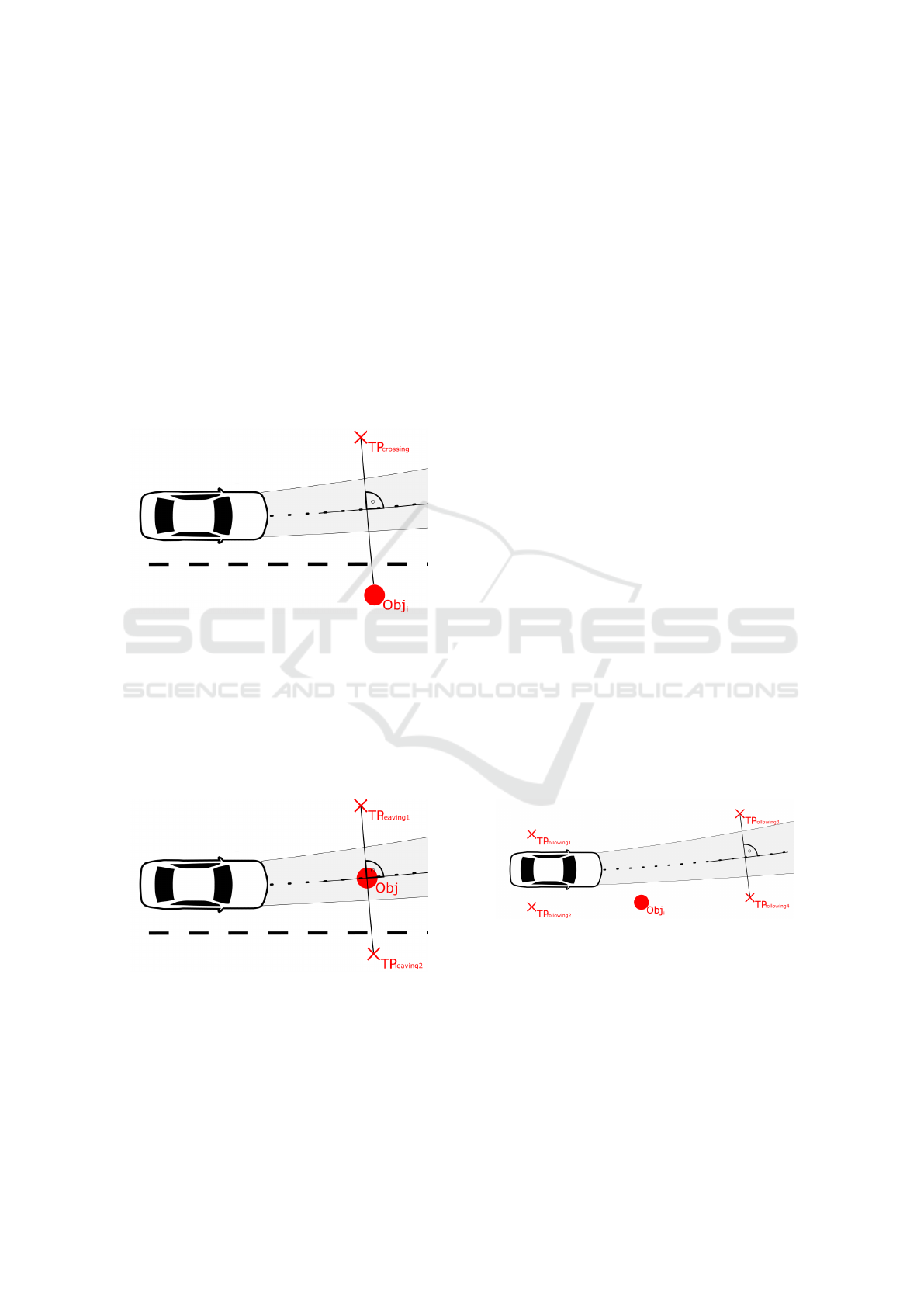
Crossing Future Ego-Trajectory
Figure1 shows the generation of the target point. In
the simplest form, the possible target point of the
pedestrian lies perpendicular on the opposite side of
the ego trajectory. This method is also possible if we
are moving in totally unstructured environment. Is
more information available, like the lane markings or
walkways, we can set TP
crossing
at the opposite side of
the lane or on the opposite walkway respectively.
Figure 1: Generation of the crossing points.
Leaving Ego Trajectory
Similar to the generation of the crossing target point,
we generate two target points on the left and right
side of the trajectory, if the object is located inside
the driving path of the vehicle. This can be seen in
Figure2. With those two points, we can detect the di-
rection, the object is leaving the ego path.
Figure 2: Generation of the leaving points.
2.1.2 Target Points from Common Motion
Hypothesis
In many cases it is too ambitious to recognize a spe-
cific goal for a dynamic object. One reason might be,
that the real goal of the dynamic object is far away and
its only midterm goal is to follow the road for a while.
In those situations, we must offer basic motion hy-
pothesis to the intention recognition process, too. We
propose ”Staying at place”, ”Moving along the course
of the ego motion” or ”Leaving the regarded area”
as those basic motion hypothesis. Those three types
form the set of the motion hypotheses target points
T P
Mot
= T P
Stay
+ T P
Mac
+ T P
Lra
(3)
Staying at Place
The target point for staying at place is set to the cur-
rent place of the dynamic object and is held there,
since the object did not move away for a certain dis-
tance. If inequation (4) is fulfilled, the location of this
target point is updated.
|X
t p
− X
ob j
| > d
max
(4)
where |X
t p
− X
ob j
| means the euclidean distance from
the target point to the position of the dynamic object
and d
max
the maximum permitted deviation from the
generated target point.
Move Along the Course of the Ego Motion
One important task for the ego vehicle is to recognize
dynamic objects, which are following the same way
or are approaching the ego vehicle. We first assume
sane behavior and set target points in a way, that the
dynamic object can pass by the ego vehicle or follow
the road on the left and right side. The distance from
the considered object to the assumed target points is
very important, because this will affect features that
are calculated from the target point, for example the
relative heading to the target point.
Figure 3: Generation of the target points for an object which
is moving along.
Leaving the Regarded Area
Taking the explained target points into account, an ob-
ject can move around the ego car, cross, leave or fol-
low the ego trajectory, but we still have a blind spot,
the dynamic object cannot move to. If the object is
located on the right side of the driving path of the ego
vehicle, it has no chance to leave the regarded area to
the right side. In this case, a target point is set on the
Intention-based Prediction for Pedestrians and Vehicles in Unstructured Environments
309
left side of the vehicle’s path, in case the object wants
to cross. But we must also set a target point on the
right of the regarded object, so it has a potential goal
on this side.
2.1.3 Target Points as Points of Interest
Points of interest are spots which are attractive for
dynamic objects. We have to distinguish online be-
tween different types of objects. Points of interest
are detected by the sensor system or entered into a
map offline. Examples for points of interest in case of
pedestrians might be crosswalks, bus stations of traf-
fic lights. For vehicles those points might be parking
lots or gateways.
2.2 Feature Calculation
One big problem in intention recognition of pedestri-
ans or vehicles in unstructured environments is find-
ing meaningful features that give hints for the future
movement of the object. This task is difficult, because
we have no lane markers or other distinctive points to
infer information from. In this proposed method, we
use target points as point of reference and we calcu-
late target point relative features between every object
and its associated target points. Additional features
are derived from the position of the generated target
point and its surroundings. Useful features are ex-
plained subsequently.
• Is the tp located in an area designated for this
class?
We assume, that all classes prefer using the space
which is designated for them. A pedestrian for
example can cross every street or motorway, but
will usually prefer walkways.
• Is the tp a point of interest?
Special target points are points of interest. They
bear stronger attraction to the dynamic objects,
because of a special function or use like cross-
walks or traffic lights.
• Is the tp blocked by law?
This feature shows, if the object is breaking law at
the attempt of reaching this target point.
• Is the tp blocked by an object?
If an object cannot reach a target point, because
another object blocks the way to it, the object will
search a different way to its goal.
• Is the tp a stay point?
This feature is true, if the target point is recog-
nized for a standing object
• What is the velocity towards the tp?
We calculate the velocity component which is
pointing towards the target point, as a feature.
• What is the acceleration towards the tp?
The same as described for the velocity is done
with the acceleration. The component of the ac-
celeration, which points towards the target point
is used as a feature.
• What is the heading towards the tp?
The angular difference between the heading of the
object and the direct line to the considered target
point.
• What is the yaw rate towards the tp?
The yaw rate towards the target point is used as a
feature.
2.3 Decision Making
After explaining the heuristics that lead to our target
points, we now show the process of finding the most
probable goal of a dynamic object. For this task, we
use a Naive Bayesian Classifier to estimate the possi-
bility for the considered point to be the future goal of
the object.
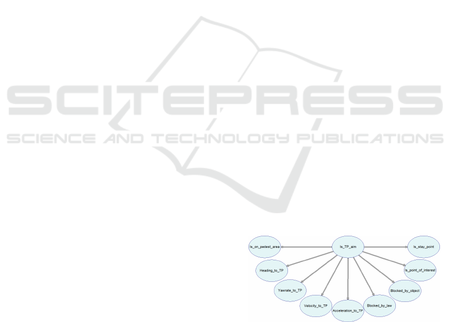
For the classification, a Naive Bayesian Network
is applied, see Figure 4, which is fed with target point
related features. The Bayesian Network was designed
with the SMILE Engine and the GeNIe Modeler from
(LCC, 2017). The process is done for every target
point, which is associated with the regarded dynamic
object. All used features are calculated online. The
features described in 2.2 are used as inputs of the
Bayesian Network. After the inference process, we
rate the target points of every dynamic object. Before
we can predict the movement of the object, we have
to choose the most probable target point.
Figure 4: Naive Bayesian Net (LCC, 2017).
2.4 Trajectory Planning and Position
Estimation
After concluding the future goals of an object, we
have to predict its movement. To accomplish this task,
VEHITS 2018 - 4th International Conference on Vehicle Technology and Intelligent Transport Systems
310

we developed a method which combines two meth-
ods. A simple linear prediction with the method of the
shortest path, calculates a trajectory from the current
position of the object to the calculated target point.
This is derived from the assumption, that people will
likely take the shortest path (Hoogendoorn and Bovy,
2004). For now the interaction with other obstacles
and objects is neglected, but is intended to be imple-
mented in a future increment of the algorithm. Fur-
ther, we want to estimate the real position of the object
by applying a Kalman Filter. By this way, we also get
an estimation of the uncertainty of the path, the dy-
namic object will take. To make the algorithm work,
we need an initialization step for new objects shown
in 2.4.1. For known objects, only the prediction step
from 2.4.2 is executed.
2.4.1 Initialization and Shortest Path Trajectory
Planning
In the initialization phase of a new object, we have to
calculate the shortest path to the chosen target point
by applying a constant velocity model. Additionally,
we have to set the values of our Kalman system for the
first time. Subsequently, the calculation of the short-
est path is described.
X
i+1
= X
i
+ T
delta
∗V
pred
(5)
when V
pred
is
V
pred
=
v
x
v
y
=
|V
meas
|cos(phi)
|V
meas
|sin(phi)
(6)
V
meas
is the measured velocity vector of the dy-
namic object. V
meas
is turned until it points to the cho-
sen target point and is now named V
pred
. Starting from
the current position of the object, the trajectory points
are calculated by adding the product of V
pred
with the
temporal interval T
delta
of the points. This process
is executed, until a trajectory point is reached, which
fulfills following inequation
X
i
T P < T
delta
∗V
pred
(7)
2.4.2 Position Estimation and Uncertainty
In the second step of the prediction, the application of
the Kalman Filter delivers us a probabilistic estima-
tion of the true position of an object in the future and
estimates the occurring uncertainty.
The Kalman Filter
The application of a Kalman filter incorporates two
steps. When we conduct the prediction step, the cur-
rent states ˆx of a system are extrapolated into the fu-
ture by applying a model F of a process. Also the co-
variance matrix is predicted by this model and an ad-
ditive component Q, which models the process noise.
The relevant equations are shown below.
ˆx
k|k−1
= F ˆx
k−1
(8)
ˆ
P
k|k−1
= F
ˆ
P
k−1
F
T
+ Q
k−1
(9)
In the second step, an update can be performed, if
there are new measurements of our state available.
For updating the position of our state, we perform
equation (10), which needs the Kalman gain
ˆ
K
k
from
equation (14) and the Innovation ˜y
k
from equation
(12). The Innovation is calculated from a difference
of the new measurement and the current system state
and the measurement matrix H. The Kalman gain is
calculated by multiplying the covariance matrix the
transposed measurement matrix and the inverse In-
novation covariance S
k
. The Innovation covariance
is a kind of summary of the uncertainty of the mea-
surement data. It is calculated from the measurement
matrix and the estimated covariance
ˆ
P
k|k−1
which is
added to the sensor noise matrix R
k
. The update of
the estimated covariance matrix
ˆ
P
k
is shown in equa-
tion (11).
ˆx
k
= ˆx
k|k−1
+
ˆ
K
k
˜y
k
(10)
ˆ
P
k
=
ˆ
P
k|k−1
−
ˆ
K
k
S
k
ˆ
K
T
k
(11)
˜y
k
= z
k
− H
k
ˆx
k|k−1
(12)
S
k
= H
k
ˆ
P
k|k−1
H
T
k
+ R
k
(13)
ˆ
K
k
=
ˆ
P
k|k−1
H
T
K
S
−1
k
(14)
For our application, we want to use the benefits of
the Kalman filter, like the state estimation dependent
on measurements and the corresponding uncertainty.
But we also want to use our recognized intention for
enhancing the state estimation. To grasp both advan-
tages in one method we now present our approach.
Combining Path Planning and State Estimation
In this paragraph, we explain how path planning and
state estimation can be combined to get a sound pre-
diction. A pseudo algorithm is shown in Algorithm 2.
The steps of the initialization phase from line one to
five are already explained in 2.4.1. How the algorithm
works can also be seen in the Fig. 6 till Fig. 8. In the
top left figure five, we can see an object which is rec-
ognized for the first time. The measured position is
X
0
. A shortest path trajectory was planned to its most
probable goal and the uncertainties are initialized, vi-
sualized by the ellipses around the trajectory points.
In the next time step k = 1 we will get a new mea-
surement from the vehicle’s state, which is X
1
, shown
Intention-based Prediction for Pedestrians and Vehicles in Unstructured Environments
311

as a red cross in Fig. 6. For a later usage, we need
the point from the shortest path trajectory of the last
step at the time of the new measurement X
1
. Even
though the points in the shortest path trajectory are
ordered isochronal, a new measurement is most likely
not taken at the time of a predicted trajectory point.
For that reason, we have to interpolate between these
points. This is done in line nine in the pseudo al-
gorithm. The interpolated point X
1int
is shown as a
brown cross in Fig. 6.
The interpolated point is set as the new Kalman state
in line ten. As last step in the update phase, we exe-
cute the Kalman update step, with the new measure-
ment as input. As a result, we get the updated vehicle
state between the interpolated state and the measured
value. In the bottom left Fig. 7, we can see the up-
dated point as green point X
1up
Algorithm 2: Object prediction algorithm.
1: Initialization phase
2: k = k
0
3: setKalmanMatrices()
4: shortPathTra j
k
= calcShortPath(X
0
)
5:
6: Iteration phase
7: while algorithm is running do
8: Update phase
9: X
k
= getMeasurement()
10: interpPoint
k
=
11: interpTemp(X
k
, shortPathTra j
k−1
)
12: setKalmanState(interpPoint
k
)
13: X
up
= per f ormKalmanU pdate(X
k
)
14:
15: Prediction phase
16: updateSystemNoise(X
up
)
17: shortPathTra j
k
= calcShortPath(X
up
)
18: for all Points in shortPathTra j
k
do
19: CoVar = calcKalmanCovarPrediction()
20: end for
21: k = k + 1
22: end while
The first step in the prediction phase, which is also
shown in Fig. 7 is the update of the process noise ma-
trix Q. By changing the process noise matrix, we want
to model a changing uncertainty of the position of the
object. As measurement of the uncertainty, we use the
difference of the current position measurement X
k
and
the former predicted position of the object at the cur-
rent time X
kint
. So we get for the new process noise
matrix
Q
k
=
f
| x
kint
− x
kup
|
0 0 0
0 f
| y
kint
− y
kup
|
0 0
0 0 f
| ˙x
kint
− ˙x
kup
|
0
0 0 0 f
| ˙y
kint
− ˙y
kup
|
(15)
Figure 5: Initialization. Figure 6: New measurement
and interpolation.
Figure 7: Kalman and pro- Figure 8: New prediction.
cess noise update.
Modeling Q in this way, we get a bigger covari-
ance matrix, if the measured position differs a lot
from the predicted. As a consequence we can show,
the uncertainty is growing if the object is leaving the
predicted trajectory. Therefore, the prediction is not
trustworthy anymore. Is the object moving along the
trajectory, the uncertainty stays small.
In Fig. 8, the steps in line 16 till 19 in the pseudo
algorithm are visualized. The green crosses represent
the new planned shortest path trajectory from line 16
in the pseudo algorithm, to the chosen target point.
After the calculation of the positions, the prediction
step of the Kalman filter is executed for the covari-
ance for every point in the trajectory. This delivers
us the uncertainty in every trajectory point, which is
displayed as green confidence ellipses around the tra-
jectory points in Fig. 8. These steps are processed for
every new measurement and therefore generate a sen-
sitive prediction of the future movement of an object
with a meaningful uncertainty estimation.
3 APPLICATION TO DIFFERENT
DYNAMIC OBJECTS
The presented approach should serve as a framework
for predicting the future motion of various objects. In
Fig. 9, you can see the main blocks of the framework
and the realized form of this work. Within this paper,
we present the application of this structure onto a pre-
dicting algorithm for pedestrians in an unstructured
environment.
Therefore, we used the described heuristic meth-
ods for target point generation and the shortest path
trajectory for path planning. For different objects or
in a better known environment, we can choose our
target point in a different way and plan the trajectory
with other algorithms. This modular design allows us
to use better fitting algorithms if the situation changes,
VEHITS 2018 - 4th International Conference on Vehicle Technology and Intelligent Transport Systems
312
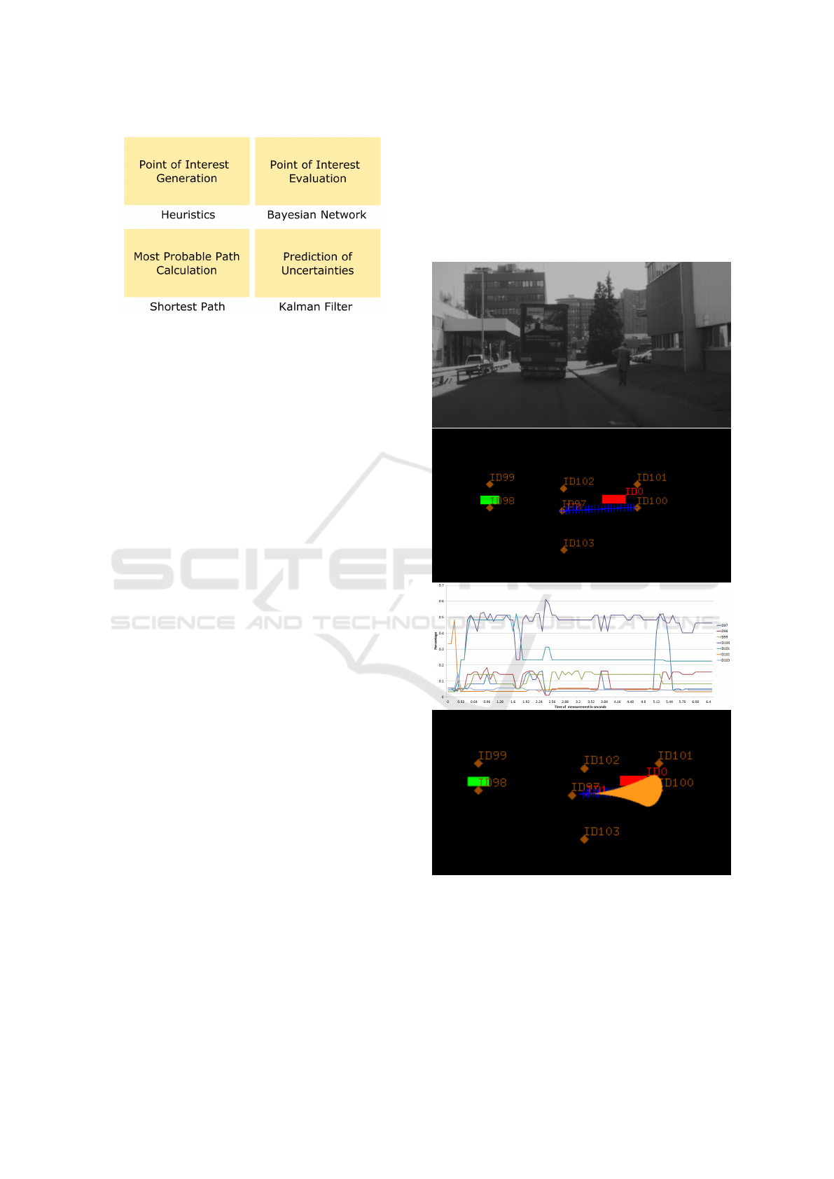
Figure 9: Modular setup of the prediction algorithm.
or respectively more information about the environ-
ment or the objects is available.
4 CONCEPT TEST WITH REAL
WORLD DATA
The presented concept was evaluated with real world
data, recorded in Frankfurt, Germany. Within this real
data test, we wanted to evaluate the presented con-
cept in terms of intention recognition for pedestrians.
As data source, a Continental MFC400 camera sen-
sor was used, which delivered classified objects and
the relevant input data for the prediction task. In Fig.
10, we can see the camera image atop and a bird’s eye
view graphic below. In the shown scene, a truck is
driving along a street and a pedestrian is going on a
walkway in the same direction. In the bird’s eye view,
we can see the truck as big red object with id 0 and
the pedestrian as red dot with id 1. The ego vehicle is
drawn as green rectangle. The intention recognition
process here is done for the pedestrian on the right
side and so the brown target points are associated to
it. We can see seven target points, whereby ID97 rep-
resents the target point which would be the goal, if the
pedestrian will stay at place. Four target points are
modeling the possibility that the pedestrian is follow-
ing the course of the ego vehicle. Those points are
ID98, ID99, ID100 and ID101. Target point ID102
would be the possible goal if the pedestrian tries to
cross the ego vehicle’s path. ID103 completes the set
for this object and would be the goal, if the pedes-
trian would like to leave the relevant area to the right.
As most probable target point, the point with id 100
is chosen and a trajectory is planned towards it. In
this concept evaluation test, we did not use all in-
puts of the Bayesian Network from Fig. 4. We as-
sumed a poor description of the environment and so
we only used the relative heading, velocity and the in-
formation whether the considered target point is a stay
point. Underneath this picture, the results for the esti-
mation of the most probable target point is visualized.
For each target point, there is depicted the course of
the percentages, if it was considered as the true aim.
In the bottommost figure, again a bird’s eye view is
shown, which depicts the error ellipses for this cur-
rent timestamp.
Figure 10: Intention recognition example with target points,
shortest path and uncertainty estimation.
5 CONCLUSIONS
In this paper, we presented a novel goal oriented ap-
proach for the task of intention recognition for dy-
Intention-based Prediction for Pedestrians and Vehicles in Unstructured Environments
313

namic objects. Possible goals are set by applying
heuristics from the human motion, trying to cover the
natural motion of humans. Additional goals are intro-
duced to recognize safety relevant motions of the ob-
ject or including frequently visited goals of humans.
The following path planning and prediction of the
movement combines the advantages of state estima-
tion and intention recognition methods. This gives us
a robust estimation of the possible trajectory and the
uncertainty of the calculated path of the considered
object. For future applications of this concept, an en-
vironment classification has to be taken into account
for a better placement of the target points. Also the
evaluation of the target points should be more envi-
ronment and context sensitive. In the path planning
task, other models should be tested to include more
information like the used time or the danger of differ-
ent possible ways to the target point. Also the inter-
action between different dynamic objects should be
modeled in the future.
REFERENCES
Dagli, I. and Reichardt, D. (2002). Motivation-based ap-
proach to behavior prediction. In IEEE Intelligent Ve-
hicle Symposium.
Gindele, T., Brechtel, S., and Dillmann, R. (2013). Learn-
ing context sensitive behavior models from observa-
tions for predicting traffic situations. In 16th Interna-
tional IEEE Conference on Intelligent Transportation
Systems (ITSC 2013), pages 1764–1771. IEEE.
Hashimoto, Y., Yanlei, G., Hsu, L.-T., and Shunsuke, K.
(2015). A probabilistic model for the estimation of
pedestrian crossing behavior at signalized intersec-
tions. In 2015 IEEE 18th International Conference on
Intelligent Transportation Systems, pages 1520–1526.
IEEE.
Hoogendoorn, S. P. and Bovy, P. H. (2004). Pedestrian
route-choice and activity scheduling theory and mod-
els. Transportation Research Part B: Methodological,
38(2):169–190.
Karasev, V., Ayvaci, A., Heisele, B., and Soatto, S. (2016).
Intent-aware long-term prediction of pedestrian mo-
tion. In Proceedings of the International Conference
on Robotics and Automation (ICRA)(May 2016).
LCC, B. (2017). Bayesfusion, lcc data analytics, mathemat-
ical modeling, decision support. recognized on 2017-
02-06.
Rehder, E., Kl
¨
oden, H., and Stiller, C. (2015). Pla-
nungsbasierte fußg
¨
angerpr
¨
adiktion. In 10. Workshop
Fahrerassistenz-systeme, page 129.
Rehder, E. and Kloeden, H. (2015). Goal-directed pedes-
trian prediction. In Proceedings of the IEEE Inter-
national Conference on Computer Vision Workshops,
pages 50–58.
Schneider, N. and Gavrila, D. M. (2013). Pedestrian path
prediction with recursive bayesian filters: A compara-
tive study. In German Conference on Pattern Recog-
nition, pages 174–183. Springer.
Tang, B., Khokhar, S., and Gupta, R. (2015). Turn pre-
diction at generalized intersections. In 2015 IEEE In-
telligent Vehicles Symposium (IV), pages 1399–1404.
IEEE.
VEHITS 2018 - 4th International Conference on Vehicle Technology and Intelligent Transport Systems
314
