
A Framework to Support Behavioral Design Pattern Detection from
Software Execution Data
Cong Liu
1
, Boudewijn van Dongen
1
, Nour Assy
1
and Wil M. P. van der Aalst
2,1
1
Department of Mathematics and Computer Science, Eindhoven University of Technology,
5600MB Eindhoven, The Netherlands
2
Department of Computer Science, RWTH Aachen University, 52056 Aachen, Germany
Keywords:
Pattern Instance Detection, Behavioral Design Pattern, Software Execution Data, General Framework.
Abstract:
The detection of design patterns provides useful insights to help understanding not only the code but also the
design and architecture of the underlying software system. Most existing design pattern detection approaches
and tools rely on source code as input. However, if the source code is not available (e.g., in case of legacy
software systems) these approaches are not applicable anymore. During the execution of software, tremendous
amounts of data can be recorded. This provides rich information on the runtime behavior analysis of software.
This paper presents a general framework to detect behavioral design patterns by analyzing sequences of the
method calls and interactions of the objects that are collected in software execution data. To demonstrate
the applicability, the framework is instantiated for three well-known behavioral design patterns, i.e., observer,
state and strategy patterns. Using the open-source process mining toolkit ProM, we have developed a tool that
supports the whole detection process. We applied and validated the framework using software execution data
containing around 1000.000 method calls generated from both synthetic and open-source software systems.
1 INTRODUCTION
As a common design practice, design patterns have
been widely applied in the development of many soft-
ware systems. The use of design patterns leads to
the construction of well-structured, maintainable and
reusable software systems (Tsantalis et al., 2006).
Generally speaking, design patterns are descriptions
of communicating objects and classes that are custo-
mized to solve a general design problem in a parti-
cular context (Gamma, 1995). The detection of im-
plemented design pattern instances during reverse en-
gineering can be useful for a better understanding of
the design and architecture of the underlying software
system. As a result, the detection of design patterns
is a challenging problem that has received a lot of at-
tention in software engineering domain (Arcelli et al.,
2009), (Arcelli et al., 2010), (Bernardi et al., 2015),
(Bernardi et al., 2014), (Dabain et al., 2015), (Dong
et al., 2009), (Fontana and Zanoni, 2011), (Niere
et al., 2002), (Shi and Olsson, 2006).
A design pattern can be seen as a tuple of software
elements, such as classes and methods, conforming to
a set of constraints. Constraints can be described from
both structural and behavioral aspects. The former
defines classes and their inter-relationships while the
latter specifies how classes and objects interact. Many
techniques have been proposed to detect design pat-
tern instances. Table 1 summarizes some typical de-
sign pattern detection approaches for object-oriented
software by considering the type of analysis (i.e., sta-
tic, dynamic and combination of both), artifacts that
are required as inputs, the description of pattern in-
stances (i.e., what roles are used to describe the pat-
tern), tool support, and the extensibility.
Based on the analysis type, these techniques can
be categorized as static analysis techniques, combina-
tion analysis techniques and dynamic analysis techni-
ques. Static analysis techniques (e.g., (Bernardi et al.,
2015), (Bernardi et al., 2014), (Dabain et al., 2015),
(De Lucia et al., 2009b), (Dong et al., 2009), (Fontana
and Zanoni, 2011), (Niere et al., 2002), (Shi and Ols-
son, 2006), (Tsantalis et al., 2006)) take the source
code as input and only consider the structural con-
nections among classes of the patterns. Therefore,
the detected pattern instances based on static analy-
sis only satisfy structural constraints. With the abun-
dance of static analysis tools on the one hand, and
the growing availability of software execution data on
the other hand, combination analysis techniques come
into reach. Combination analysis techniques (e.g.,
(De Lucia et al., 2009a), (Heuzeroth et al., 2003), (Ng
Liu, C., van Dongen, B., Assy, N. and M. P. van der Aalst, W.
A Framework to Support Behavioral Design Pattern Detection from Software Execution Data.
DOI: 10.5220/0006688000650076
In Proceedings of the 13th International Conference on Evaluation of Novel Approaches to Software Engineering (ENASE 2018), pages 65-76
ISBN: 978-989-758-300-1
Copyright
c
2019 by SCITEPRESS – Science and Technology Publications, Lda. All rights reserved
65
Table 1: Summary of Existing Design Pattern Detection Approaches.
Reference Analysis Type Required Artifacts Pattern Instance Tool Extensibility
(Niere et al., 2002) static analysis source code class roles 3 7
(Shi and Olsson, 2006) static analysis source code class & method roles 3 3
(Tsantalis et al., 2006) static analysis source code class roles 3 7
(Dong et al., 2009) static analysis source code class roles 3 7
(De Lucia et al., 2009b) static analysis source code class roles 3 7
(Fontana and Zanoni, 2011) static analysis source code class roles 3 7
(Bernardi et al., 2014) static analysis source code class roles 3 7
(Dabain et al., 2015) static analysis source code class roles 3 7
(Bernardi et al., 2015) static analysis source code class roles 3 7
(Heuzeroth et al., 2003) combination analysis source code & execution data class & method roles 7 7
(Wendehals and Orso, 2006) combination analysis source code & execution data class & method roles 7 7
(Von Detten et al., 2010) combination analysis source code & execution data class roles 3 7
(Ng et al., 2010) combination analysis source code & execution data class roles 7 7
(De Lucia et al., 2009a) combination analysis source code & execution data class roles 3 7
(Arcelli et al., 2009), (Arcelli et al., 2010) dynamic analysis execution data unclear 7 7
et al., 2010), (Von Detten et al., 2010), (Wendehals
and Orso, 2006)) take as input the candidate design
pattern instances that are detected by static analysis
tools and software execution data, and check whet-
her the detected candidate pattern instances conform
to the behavioral constraints. Therefore, the identified
pattern instances using combination techniques match
both structural and behavioral constraints. Compa-
red with static analysis techniques, the combination
techniques can eliminate some of the false positives
caused by static techniques because the candidate pat-
tern instances are examined with respect to the beha-
vioral constraints.
Both the static analysis and combination analysis
techniques require source code as input. However, if
the source code is not available (e.g., in case of legacy
software systems) these approaches are not applicable
anymore. Dynamic analysis techniques can detect de-
sign pattern instances directly from the software exe-
cution data by considering sequences of the method
calls and interactions of the objects that are involved
in the patterns. However, existing researches into dy-
namic analysis techniques suffer from the following
problems that restrict the application:
• Unclear Description of Detected Pattern In-
stances. A design pattern instance is represen-
ted as a tuple of the participating classes or met-
hods each acting a certain role. Existing dynamic
techniques (Arcelli et al., 2009), (Arcelli et al.,
2010) do not clearly define pattern instances. This
may influence the precision of behavioral con-
straint checking as some (class or method) roles
that need to be verified are not specified. In ad-
dition, a lot of manual work is required to under-
stand the detected pattern instances if they are not
described properly (Pettersson et al., 2010).
• Missing Explicit Definition of Pattern Instance
Invocation. To check the behavioral constraints
of a candidate pattern instance, execution data that
characterize the behavior of the candidate are nee-
ded. Normally, the behavioral constraints are de-
fined based on the notion of pattern instance in-
vocation which represents one independent exe-
cution of the underlying pattern instance. One
needs to check the behavioral constraints against
each pattern instance invocation. Existing dyna-
mic techniques do not define clearly a pattern in-
stance invocation, which causes inaccurate beha-
vioral constraint checking.
• Inability to Support Novel Design Patterns. An
approach is extensible if it can be easily adapted to
some novel design patterns rather than only sup-
porting a sub-group of existing patterns. Existing
dynamic analysis approaches do not provide ef-
fective solutions to support new emerging design
patterns with novel structural and behavioral cha-
racteristics. This limits the applicability and ex-
tensibility of existing approaches in the large.
• Lacked Tool Support. The usability of an appro-
ach heavily relies on its tool availability. Existing
dynamic analysis approaches do not provide usa-
ble tools. This unavailability prohibits other rese-
archers to reproduce the experiment and compare
their new approaches.
In this paper, a general framework is proposed to
support the detection of design pattern instances from
execution data with full consideration of the limita-
tions of existing work. We clearly define a pattern
instance as a set of roles that each is acted by a class
or a method. In addition, to ensure accurate beha-
vioral constraint checking for execution data that in-
volve multiple pattern instance invocations, we preci-
ENASE 2018 - 13th International Conference on Evaluation of Novel Approaches to Software Engineering
66

sely define the notion of pattern instance invocation
and propose a refactoring of the execution data (tra-
ces) in such a way that each refactored trace repre-
sents a pattern instance invocation. Our framework
definition is generic and can be instantiated to support
new patterns (or new pattern variants). To validate the
proposed approach, we have developed a tool, named
DEsign PAttern Detection from execution data (De-
PaD), which supports the whole detection process for
observer, state and strategy design patterns.
The rest of this paper is organized as follows.
Section 2 defines some preliminaries. Section 3 for-
malizes the general framework. Section 4 details each
step of the instantiation of the framework by taking
the observer pattern as a running example. Section 5
introduces the tool support. Section 6 conducts expe-
rimental evaluation. Section 7 discusses some threats
to the validity of our approach. Finally, Section 8 con-
cludes the paper and presents further directions.
2 PRELIMINARIES
Given a set S, |S| denotes the number of elements
in S. We use ∪, ∩ and \ for the union, intersection
and difference of two sets.
/
0 denotes the empty set.
The powerset of S is denoted by P (S) = {S
0
|S
0
⊆ S}.
f : X → Y is a total function, i.e., dom( f ) = X is the
domain and rng( f ) = { f (x)|x ∈ dom( f )} ⊆ Y is the
range. g : X 9Y is a partial function, i.e., dom(g) ⊆ X
is the domain and rng(g) = {g(x)|x ∈ dom(g)} ⊆ Y is
the range. A sequence over S of length n is a function
σ : {1,2,...,n} → S. If σ(1) = a
1
,σ(2) = a
2
,...σ(n) =
a
n
, we write σ = ha
1
,a
2
,...a
n
i. |σ| = n represents the
length of sequence σ is n. The set of all finite se-
quences over set S is denoted by S
∗
. Let σ ∈ S
∗
be a
sequence, σ(i) represents the ith element of σ where
1 ≤ i ≤ |σ|. Given a sequence σ and an element e, we
have e ∈ σ if ∃i : 1 ≤ i ≤ |σ| ∧ σ(i) = e.
To be able to refer to the different entities, we in-
troduce the following universes. Let U
M
be the met-
hod call universe, U
N
be the method universe, U
C
be
the universe of classes and interfaces, U
O
be the ob-
ject universe where objects are instances of classes,
U
R
be the role universe and U
T
be the time universe.
To relate these universes, we use the following notati-
ons: For any m ∈ U
M
,
b
m ∈ U
N
is the method of which
m is an instance. For any o ∈ U
O
,
b
o ∈ U
C
is the class
of o. pc : U
N
→ P (U
C
) defines a mapping from a
method to its parameter class set. ms : U
C
→ P (U
N
)
defines a mapping from a class to its method set.
iv : U
N
→ P (U
N
) defines a mapping from a method
to its invoked method set.
In this paper, we mainly reason based on the soft-
ware execution data. A method call is the basic unit of
software execution data (Liu et al., 2016), (Leemans
and Liu, 2017) and its attributes can be defined as fol-
lows:
Definition 1 (Method Call, Attribute). For any m ∈
U
M
, the following standard attributes are defined:
• η : U
M
→ U
O
is a mapping from method calls to
objects such that for each method call m ∈ U
M
,
η(m) is the object containing the instance of the
method
b
m.
• c : U
M
→ U
M
∪ {⊥} is the calling relation among
method calls. For any m
i
,m
j
∈ U
M
, c(m
i
) = m
j
means that m
i
is called by m
j
, and we name m
i
as the callee and m
j
as the caller. Specially, for
m ∈ U
M
, if c(m) = ⊥, then
b
m is a main method.
• p : U
M
→ U
∗
O
is a mapping from method calls to
their (input) parameter object sequences such that
for each method call m ∈ U
M
, p(m) is a sequence
of (input) parameter objects of the instance of the
method
b
m.
• t
s
: U
M
→ U
T
is a mapping from method calls to
their timestamps such that for each method call
m ∈ U
M
, t
s
(m) is start timestamp of the instance
of method
b
m.
• t
e
: U
M
→ U
T
is a mapping from method calls to
their timestamps such that for each method call
m ∈ U
M
, t
e
(m) is end timestamp of the instance of
method
b
m.
Definition 2 (Software Execution Data). Software
execution data is defined as a set of method calls, i.e.,
SD ⊆ U
M
.
3 A GENERAL FRAMEWORK TO
DETECT DESIGN PATTERNS
FROM EXECUTION DATA
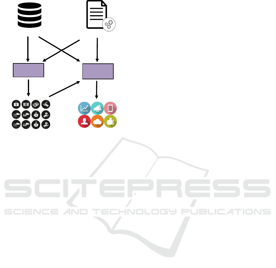
Fig. 1 shows an overview of the framework to detect
behavioral design patterns. It involves two main pha-
ses, i.e., candidate pattern instance discovery and be-
havioral constraint checking. Software execution data
and design pattern specification are required as the in-
put artifacts. The design pattern specification and the
two phases are detailed in the following.
3.1 Design Pattern Specification
A design pattern specification precisely defines how
a design pattern should be organized, which includes
the role set that is involved in the design pattern, the
A Framework to Support Behavioral Design Pattern Detection from Software Execution Data
67
Discovery
Checking
Validated Pattern Instances
Software Execution Data
Design Pattern Specification
Candidate Pattern Instances
Phase 1
Phase 2
Figure 1: General Overview of the Framework.
definition of pattern instance, a set of structural con-
straints, the definition of pattern instance invocation,
and a set of behavioral constraints.
Definition 3 (Design Pattern Specification). A design
pattern is defined as DP = (U
P
R
,rs,sc, pii,bc) such
that:
• Role Set. U
P
R
⊆ U
R
is the role set of a design pat-
tern.
• Pattern Instance. rs : U
P
R
→ U
N
∪ U
C
is a map-
ping from the roles to their values (methods or
classes). Essentially, it is an implementation of
the pattern.
• Structural Constraints. sc : (U
P
R
→U
N
∪ U
C
)
→ IB with IB = {true,false} is used to check the
structural constraints of a pattern instance.
• Pattern Instance Invocation Identification.
pii : P (U
M
) → P (P (U
M
)) is a function that
identifies a set of pattern instance invocations
from the method call set of a pattern instance.
• Behavioral Constraints. bc : P (P (U
M
))→IB is
used to check the behavioral constraints of all in-
vocations of a pattern instance.
Note that the way invocations are identified is spe-
cific to each type of design pattern and independent
of the number of runs included in the software exe-
cution data. In addition, for some structural patterns
(e.g., adapter pattern, composite pattern), they do not
necessary contain the definition of pattern instance in-
vocation and behavioral constraints.
3.2 Phase 1: Candidate Pattern
Instance Discovery
By taking the execution data as input, we need to
discover a set of candidate pattern instances, i.e.,
finding the values (classes or methods) that play
certain roles in the pattern instances. Formally,
crs : U
P
R
9 U
N
∪ U
C
is a partial function that maps
a sub-set of roles to its corresponding values. In
our case, we have dom(crs) =
/
0, i.e., all roles do
not have values and we need to brute force all
possibilities according to the structural constraints.
dis : (U
P
R
9U
N
∪ U
C
)→P (U
P
R
→ U
N
∪ U
C
) is the
discovery function that maps an empty pattern in-
stance to a set of complete pattern instances.
For any crs ∈ U
P
R
9 U
N
∪ U
C
,rs ∈ dis(crs), we
have sc(rs)=true, i.e., the structural constraints hold
for each discovered candidate pattern instance.
Existing static pattern instances discovery approa-
ches focus on structural analysis of classes, operations
and their inter-relationships (e.g., inheritance, realiza-
tion, dependency) by exploring the source code. As
for the discovery from execution data, class operati-
ons and some of the relationships, e.g., dependency
and inheritance relationships, can be recovered. Rea-
lization relationship cannot be recovered as the inter-
faces cannot be instantiated and recorded during exe-
cution. Hence, some of the roles that are played by
interfaces as detected from source code will be repla-
ced by the implemented classes from the execution
data.
3.3 Phase 2: Behavioral Constraint
Checking
The pattern instance discovery takes as input the exe-
cution data and return a set of candidate pattern in-
stances by considering only the structural constraints
of the pattern, i.e., relationship among classes and
methods. So the discovered candidate pattern instan-
ces inevitably contain false positives, especially for
behavioral design patterns. For each candidate pat-
tern instance rs and its execution data SD, we check
whether the behavioral constraints given in the speci-
fication are satisfied with respect to all invocations of
a pattern instance, i.e., bc(pii(SD)) = true.
3.4 Instantiation of the Framework
Given a novel design pattern X, the framework is re-
quired to support its detection. To execute the frame-
work, design pattern specification of pattern X and
software execution data that cover the behavior of
such pattern are required. To test the applicability,
ENASE 2018 - 13th International Conference on Evaluation of Novel Approaches to Software Engineering
68

+register()
+unregister()
+notify()
Subject
+update()
«interface»
Observer
+update()
ConcreteObserver
observers
foreach o in observers{
0->update()
}
Figure 2: Structure of the Observer Design Pattern.
we instantiate the proposed methodology to discover
the observer, state and strategy patterns. Detailed ex-
planations of the applicability to the observer pattern
is given in the next section with a running example.
For the state and strategy patterns, their instantiation
details are not repeated for page limits.
4 DETECTION OF OBSERVER
DESIGN PATTERN
We first use the observer design pattern as a running
example to illustrate the proposed framework. This
is one particular instance of our general framework.
Later we provide other examples.
4.1 Observer Design Pattern and A
Running Example
The observer design pattern (Gamma, 1995) defi-
nes one-to-many dependency between objects so that
when one object changes state, all its dependents are
automatically notified. The structure of the observer
design pattern is shown in Fig. 2. The key partici-
pants of this pattern are Subject and Observer. In this
pattern, there are many Observer objects which are
observing a particular Subject object. Observers are
interested and want to be notified when the Subject
undergoes a change. Therefore, they register themsel-
ves to that Subject. When an observer loses interest
in the subject they simply unregister from it.
More specifically, a Subject is a class that (1)
keeps track of a list of Observer references; (2) sends
notifications to its registered observers on state chan-
ges; and (3) provides interfaces for registering and de-
registering Observer objects. The Observer interface
defines an update interface for objects that should be
notified when the subject changes. When the state of
Subject is changed, it invokes the notify method that
implements a sequential call of the update method on
all registered Observer objects.
The following naming conventions refer to roles
that are involved in the observer pattern. Note that
this naming convention is only used for explanations
and our approach does not rely on these names.
• Observer is an interface that defines an updating
interface for objects that should be notified of
changes;
• Subject is a class that stores state of interest to Ob-
server objects and sends notifications to its inte-
rested objects when its state changes;
• notify is a method that is responsible for notifying
the observers of a state change in the Subject;
• update is a method implemented by the Observer
objects and can be called by the notify method;
• register is a method responsible for adding Obser-
ver objects to a Subject object; and
• unregister is a method responsible for removing
Observer objects from a Subject object.
A concrete implementation of the observer pattern
is AISWorld which is an academic community soft-
ware for researchers and practitioners. All its mem-
bers subscribe to the news updates by registering to
a public mailing server. When new events of the
community occur, the mailing server will push these
news items to all its subscribed members. Community
members can also unsubscribe if they do not want to
follow any more.
An excerpt of the execution data that are genera-
ted by an independent run of the AISWorld software
are given in Table 2.
1
Its behavior can be described
as: (1) three Member objects (Observer objects) are
first created and registered to a MailingServer object
(Subject object); (2) the notifyMember method of the
MailingServer object is called and the update methods
of the three registered Member objects are invoked
during its execution; (3) these three Member objects
are unregistered from the MailingServer object; (4)
another two Member objects are created and registe-
red to the second MailingServer object; (5) the notify-
Member method of the second MailingServer object
is called and the update methods of the two registered
Member objects are invoked during its execution; and
(6) these two Member objects are unregistered from
the second MailingServer object.
1
Note: methods are fully quantified including package,
class and method names. init represents the constructor of
a class.
A Framework to Support Behavioral Design Pattern Detection from Software Execution Data
69

Table 2: An Example of Software Execution Data
ID (Callee) Method (Callee) P O (Callee) O Caller Method Caller O Start Time End Time
m
1
Member.init – 1807970113 mainclass.main – 709020268 709120368
m
2
Member.init – 1807567788 mainclass.main – 709244786 709267786
m
3
Member.init – 1488142454 mainclass.main – 709378641 709378641
m
4
MailingServer.init – 1333401746 mainclass.main – 717761066 717961966
m
5
MailingServer.register 1807970113 1333401746 mainclass.main – 718086509 718086619
m
6
MailingServer.register 1807567788 1333401746 mainclass.main – 718261847 718361447
m
7
MailingServer.register 1488142454 1333401746 mainclass.main – 718420506 718588315
m
8
MailingServer.notifyMembers – 1333401746 mainclass.main – 718686715 719110738
m
9
Member.update – 1807970113 MailingServer.notifyMembers 1333401746 718788715 718880715
m
10
Member.update – 1807567788 MailingServer.notifyMembers 1333401746 718929841 718929941
m
11
Member.update – 1488142454 MailingServer.notifyMembers 1333401746 719050867 719100467
m
12
MailingServer.unregister 1807970113 1333401746 mainclass.main – 719270253 719370253
m
13
MailingServer.unregister 1807567788 1333401746 mainclass.main – 719408812 719507712
m
14
MailingServer.unregister 1488142454 1333401746 mainclass.main – 719570465 719880462
m
15
Member.init – 1491288577 mainclass.main – 719712873 719722873
m
16
Member.init – 805469502 mainclass.main – 719843307 719943908
m
17
MailingServer.init – 1936493073 mainclass.main – 720398401 720698461
m
18
MailingServer.register 1491288577 1936493073 mainclass.main – 720719568 720919968
m
19
MailingServer.register 805469502 1936493073 mainclass.main – 721077514 721276516
m
20
MailingServer.notifyMembers – 1936493073 mainclass.main – 721526122 721976868
m
21
Member.update – 1491288577 MailingServer.notifyMembers 1936493073 721526122 721626122
m
22
Member.update – 805469502 MailingServer.notifyMembers 1936493073 721825906 721875908
m
23
MailingServer.unregister 1491288577 1936493073 mainclass.main – 722279646 722379646
m
24
MailingServer.unregister 805469502 1936493073 mainclass.main – 722579858 722779768
m
25
TestMail.mainclass.main 5336152135 – – – 703720242 723873758
Note: O is short for object, P is short for parameter and – means the value is unavailable.
4.2 Candidate Observer Pattern
Instances Discovery
In this subsection, we introduce how to discover can-
didate observer pattern instances from software exe-
cution data. Note that different levels of granularity
can be used for the roles of a design pattern. For
example, most existing works (e.g., (Bernardi et al.,
2015), (Bernardi et al., 2014), (Dabain et al., 2015),
(De Lucia et al., 2009a), (De Lucia et al., 2009b),
(Dong et al., 2009), (Fontana and Zanoni, 2011), (Ng
et al., 2010), (Niere et al., 2002) and (Tsantalis et al.,
2006)) use a tuple of Subject and Observer as roles
of observer pattern. The coarse-grained descriptions
of pattern instances are not enough to preform pre-
cise behavioral constraint checking. This paper aims
to give a complete description of design patterns (in
terms of class and method roles) . The following de-
finition specifies the observer pattern in detail.
Definition 4 (Role Set and Pattern Instance of Ob-
server Pattern). Role set of the observer pattern is
defined as U
O
R
= U
O
RC
∪ U
O
RM
where U
O
RC
={Sub,Obs}
and U
O
RM
={not,upd, reg, unr}. rs
o
: U
O
R
→ U
C
∪ U
N
is a mapping from the role set of observer pattern
to their values such that ∀r ∈U
O
RC
: rs
o
(r) ∈ U
C
and
∀r ∈U
O
RM
: rs
o
(r) ∈ U
N
.
An observer pattern instance is an implementation
of the observer pattern and it defines a binding from
the role set to its values. The discovery process aims
to find the missing values for all roles involved in the
role set of observer pattern with respect to the struc-
tural constraints. The following definition formalizes
the structural constraints of the observer pattern.
Definition 5 (Structural Constraints of Observer Pat-
tern). For each observer pattern instance rs
o
, we have
sc
o
(rs
o
)=true iff:
• rs
o
(not) ∈ ms(rs
o
(Sub)), i.e., notify is a method of
Subject; and
• rs
o
(reg) ∈ ms(rs
o
(Sub)), i.e., register is a method
of Subject; and
• rs
o
(unr) ∈ ms(rs
o
(Sub)), i.e., unregister is a met-
hod of Subject; and
• rs
o
(upd) ∈ ms(rs
o
(Obs)), i.e., update is a method
of Observer; and
• rs
o
(Obs) ∈ pc(rs
o
(reg)), i.e., register should con-
tain a parameter of Observer type; and
• rs
o
(Obs) ∈ pc(rs
o
(unr)), i.e., unregister should
contain a parameter of Observer type; and
• rs
o
(Obs) /∈ pc(rs
o
(not)), i.e., notify should not
contain a parameter of Observer type; and
• rs
o
(upd) ∈ iv(rs
o
(not)), i.e., update should be in-
voked by notify; and
ENASE 2018 - 13th International Conference on Evaluation of Novel Approaches to Software Engineering
70

• rs
o
(reg) 6= rs
o
(unr), i.e., register and unregister
can not be played by the same method.
Based on the structural constraints, we propose an
algorithm to discover candidate observer pattern in-
stances from software execution data. Before outli-
ning the algorithm, some important concepts and no-
tations that are used in the reminder are introduced.
Given software execution data SD, we define:
• cs(SD) = {
[
η(m)|m ∈ SD} is the class set involved
in the software execution data SD;
• For any c ∈ U
C
, ms(c,SD) = {
b
m|
[
η(m) = c} is the
method set of class c in execution data SD;
• For any n ∈ U
N
, pc(n,SD) = {
b
o|∃m ∈ SD :
b
m = n ∧ o ∈ p(m)} is the parameter class set of
method n in the software execution data SD; and
• For any n ∈ U
N
, iv(n,SD) = {
b
m|m ∈ SD∧
d
c(m) = n} is the invoked method set of method n
in the software execution data SD.
For the discovery of observer pattern instances
from execution data, we first identify a set of possible
values for each role as intermediate results. This
is defined as rs
o
∗
: U
O
R
→ P (U
C
∪ U
N
). Then we
define a function ω that generates a set of pattern
instances by exploiting all possible combinati-
ons of different role values. Formally, we have
ω : (U
O
R
→ P (U
N
∪ U
C
)) → P (U
O
R
→ U
N
∪ U
C
).
For any rs
o
∗
∈ U
O
R
→ P (U
C
∪ U
N
), (1) for
any rs
o
∈ ω(rs
o
∗
): dom(rs
o
) = U
O
R
; (2) for
any r ∈ U
O
R
: rs
o
∗
(r) =
S
rs
o
∈ω(rs
o
∗
)
rs
o
(r); (3)
@rs
o
,rs
o0
∈ ω(rs
o
∗
): ∀r ∈ U
O
R
, rs
o
(r) = rs
o0
; and
(4) |ω(rs
o
∗
)| =
∏
r∈U
O
R
|rs
o
∗
(r)|.
Assume that design pattern W invol-
ves with two type of roles (X and Y), we
have rs
w
∗
(X) = {a,b} and rs
w
∗
(Y) = {c,d}.
Then we generate four pattern instances
ω(rs
w
∗
)={{rs
w
1
(X)= {a},rs
w
1
(Y)= {c}},{rs
w
2
(X)= {a},
rs
w
2
(Y) = {d}},{rs
w
3
(X) = {b},rs
w
3
(Y) = {c}},{rs
w
4
(X)
= {b},rs
w
4
(Y) = {d}}. The pseudocode description of
the observer pattern instance discovery is given in the
following algorithm.
As the algorithm discovers a set of candidate
observer pattern instances using the structural con-
straints and the software execution data, it inevitably
produces some false positives. For example, by taking
the software execution data in Table 2 as input, we
obtain two candidate observer pattern instances using
Algorithm 1, denoted as rs
o
1
and rs
o
2
, as shown in Ta-
ble 3. Note that the methods that play the roles of
register and unregister are undistinguishable by only
considering the structural constraints.
4.3 Behavioral Constraint Checking
This section introduces how to check whether a dis-
covered candidate observer pattern instance conforms
to the behavioral constraints. Because one or more
invocations may be involved in the execution data,
we need to identify independent observer pattern in-
stance invocations from the execution data. Because
not all method calls in the software execution data are
relevant with the observer pattern instance that we are
going to check, we first define execution data for an
observer pattern instance.
Definition 6 (Execution Data of Observer Pat-
tern Instance). Let rs
o
be an observer pat-
tern instance and SD be the execution data.
SD
O
= {m ∈ SD | ∃r ∈ U
O
R
: rs
o
(r) =
b
m} are the
execution data of observer pattern instance rs
o
.
According to specification of observe design pat-
tern, an observer pattern instance invocation starts
with the creation of one Subject object and involves
all method calls such that: (1) the method plays a role
in the observer pattern instance; and (2) its object is
the Subject object or its caller object is the Subject
object and the object is an Observer object. In ad-
dition, by taking the same observer pattern instance
execution data as input, the set of identified observer
pattern instance invocations should be unique.
Definition 7 (Observer Pattern Instance Invocation).
Let rs
o
be an observer pattern instance and SD
O
be
its execution data. We define invocation set of rs
o
as
pii
o
(SD
O
) = {I
1
,I
2
,. .., I
n
} ⊆ P (SD
O
), such that:
• for any I
i
∈ pii
o
(SD
O
), m ∈ I
i
where 1 ≤ i ≤ n,
there exists o ∈ U
O
and rs
o
(Sub) =
b
o such that:
– (
b
m = rs
o
(reg) ∨
b
m = rs
o
(unr) ∨
b
m = rs
o
(not))∧
(η(m) = o), i.e., the object of each method call
is the Subject object and the method should
play the role of register, unregister or notify; or
–
b
m= rs
o
(upd)∧η(c(m))=o∧rs
o
(Obs) =
[
η(m),
i.e., the caller object of each method call is the
Subject object and the method should play the
role of update.
• for any I
i
,I
j
∈ pii
o
(SD
O
), m ∈ I
i
, m
0
∈ I
j
where
1≤ i <j ≤n, there does not exist o∈ U
O
and rs
o
(Sub) =
b
o such that (η(m) = o∨
η(c(m)) = o) ∧ (η(m
0
) = o∨η(c(m
0
)) = o).
Considering the software execution data
in Table 2, the execution data of can-
didate observer pattern instance rs
o
1
is
SD
O
= {m
i
|5 ≤ i ≤ 14 ∧ 18 ≤ i ≤ 24}. We have
pii
o
(SD
O
) = {I
1
O
,I
2
O
} with I
O
1
={m
i
|5 ≤ i ≤ 14} and
I
O
2
={m
i
| 18 ≤ i ≤ 24} be two invocations.
A Framework to Support Behavioral Design Pattern Detection from Software Execution Data
71
Algorithm 1: Candidate observer pattern instances discovery.
Input: Software execution data SD.
Output: Observer pattern instance set RS.
1 RS ←
/
0, ClassSet ← cs(SD). /**initialization.**/
2 for c
i
∈ ClassSet do
3 /**subject class should at least contain three methods**/
4 if |ms(c
i
,SD)| ≥ 3 then
5 for c
j
∈ ClassSet do
6 /**observer class should at least contain one method.**/
7 if c
i
6= c
j
& |ms(c
j
,SD)| ≥ 1 then
8 /**create intermediate result op.**/
9 op(Sub)←{c
i
}, op(Obs)←{c
j
}, op(not)←
/
0,
10 op(upd) ←
/
0, op(reg) ←
/
0, op(unr) ←
/
0;
11 for m
i
∈ ms(c
i
,SD) do
12 /**register and unregister are played by methods with a parameter of observer class.**/
13 if c
j
∈ pc(m
i
,SD) then
14 /**set values for register and unregister roles of op.**/
15 op(reg) ← op(reg) ∪ {m
i
};
16 op(unr)←op(unr)∪{m
i
};
17 if |op(reg)| ≥ 2 then
18 for m
j
∈ ms(c
i
,SD) do
19 /**notify should not contain a parameter of observer class.**/
20 if m
j
/∈op(reg) & c
j
/∈pc(m
j
,SD) then
21 for m
k
∈ iv(m
j
,SD) do
22 /** update is invoked by notify.**/
23 if m
k
∈ ms(c
j
,SD) then
24 op(not) ← op(not) ∪ {m
j
};
25 op(upd) ← op(upd) ∪ {m
k
};
26 /** for each op, we generate all possible role to value combinations as candidate instances.**/
27 for rs ∈ ω(op) do
28 if rs(reg) 6= rs(unr) then
29 RS ← RS ∪ {rs};
30 return All detected observer pattern instances RS.
Table 3: Two Observer Candidate Pattern Instances.
Sub Obs not upd reg unr
rs
o
1
MS. M. notifyM update register unregister
rs
o
2
MS. M. notifyM update unregister register
MS. and M. are short for MailingServer and the Member.
After obtaining candidate pattern instances and re-
factoring execution data by invocation identification,
we can check whether a candidate conforms to the be-
havioral constraints. To this end, we formally define
the behavioral constraints of the observer pattern. The
following notations and operators are defined on the
basis of each invocation.
Given an observer pattern instance invocation
I ⊆ SD, we define:
• For any n ∈ U
N
, N(I,n) = {m ∈ I|
b
m = n} is a set
of method calls with n being its method in I;
• For any M ⊆ I, CO(M) = {o∈U
O
|∃m∈ M
: η(m)= o}is the object set of M;
• For any n ∈ U
N
, c ∈ U
C
, PS(I,n,c) = {o ∈ U
O
|
∃m ∈ I :
b
m = n∧o∈p(m) ∧
b
o = c} is a set of (in-
put) parameter objects of method calls with n
being their method and these objects are of class
type c in I;
• For any m ∈ U
M
, I
v
(I, m) = {m
0
∈ I|c(m
0
) = m}
is the invoked method call set of method call m
in I; and
• For any m ∈ U
M
, Pre(I,m) ={m
0
∈I|t
e
(m
0
)
< t
s
(m)} is the set of method calls that are
invoked before method call m in I.
Definition 8 (Behavioral Constraints of Observer Pat-
tern). For each observer pattern instance rs
o
, the be-
havioral constraints bc
o
(pii
o
(SD
O
)) = true iff there
exists an invocation I ∈ pii
o
(SD
O
) such that:
• |N(I,rs
o
(not))| ≥ 1 ∧ |N(I,rs
o
(upd))| ≥ 1∧
|N(I,rs
o
(reg))| ≥ 1 ∧|N(I,rs
o
(unr))| ≥ 1, i.e.,
for each observer pattern invocation, notify,
update, register and unregister methods should
be invoked at least once; and
•
∀
o∈PS(I,rs
o
(reg),rs
o
(Obs))∪PS(I,rs
o
(unr),rs
o
(Obs))
(
∃
m∈I
b
m =
ENASE 2018 - 13th International Conference on Evaluation of Novel Approaches to Software Engineering
72

Input: Software Execution Data
Output: Pattern Instances
Plugin
Plugin description
Figure 3: Screenshot of the DePaD.
rs
o
(reg) ∧ o ∈ p(m)) ∧(
∀
m∈I
∃
m
0
∈I
b
m = rs
o
(reg) ∧
b
m
0
= rs
o
(unr)∧o ∈p(m) ∧o∈ p(m
0
) ∧ t
e
(m)< t
s
(m
0
)),
i.e., for each observer pattern invocation an ob-
server object should be first registered to the
Subject object and then unregistered from it; and
•
∀
m∈I∧
b
m=rs
o
(not)
CO(N(I
v
(I, m),rs
o
(upd))) = (PS(Pre
(I, m),rs
o
(reg), rs
o
(Obs)) \ PS(Pre(I,m),rs
o
(unr),
rs
o
(Obs))), i.e., a notify method should invoke the
update methods of all Observer objects that are
currently registered to the Subject object.
A candidate observer pattern instance is valid if
there exists at least one invocation that satisfies all
behavioral constraints, otherwise, it is not valid. Con-
sidering the candidates in Table 3 and its invocations
I
O
1
and I
O
2
, rs
o
1
is a valid observer pattern instance but
rs
o
2
is not. This is because the second behavioral con-
straint is violated, i.e., some observer objects are only
registered to the subject object but not unregistered,
for both invocations when checking rs
o
2
.
5 TOOL IMPLEMENTATION
The proposed approach to detect behavioral design
pattern has been implemented as a plug-in, called DE-
sign PAttern Discovery from execution data (DePaD),
in our ProM 6 package.
2
It takes the software execu-
tion data as input, and returns a set of design pattern
instances. Currently, this tool supports observer pat-
tern, state pattern and strategy pattern. A snapshot of
the tool is shown in Fig. 3.
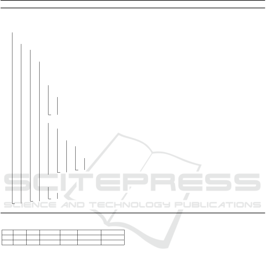
Fig. 4 shows the observer pattern instance rs
o1
by
taking the execution data that are generated by three
runs of the AISWorld software as input. Note that the
Run/Invocation Count indicates the number of runs in
the input software execution data and the number of
invocations that support the current pattern instance.
2
We will link to the code in the camera-ready version
Run
Figure 4: A Detected Observer Pattern Instance.
All experimental results in the following section are
based on this tool.
6 EMPIRICAL EVALUATION
In this section, we evaluate our approach using both
synthetic and open-source software systems that over-
all produce around 1000.000 method calls in the exe-
cution data. For these experiments we used a laptop
with a 2.40 GHz CPU, Windows 8.1 and Java SE 1.7.0
67 (64 bit) with 4 GB of allocated RAM.
6.1 Subject Software Systems and
Execution Data
For our experiments, we use six synthetic software sy-
stems. Each system implements one or more design
patterns. For each synthetic software system, we cre-
ate its execution data by instrumenting different exe-
cution scenarios. The advantages of using synthetic
software systems are that we have enough up-to-date
knowledge to (1) collect execution data that cover all
scenarios; and (2) evaluate the accuracy (in terms of
precision and recall) of our proposed approach.
In addition, to show the applicability and scala-
bility of our approach for real-life software systems,
we use the execution data that were collected from
three open-source software. Different from synthetic
software that we have enough knowledge to guarantee
that the execution data cover all software usage sce-
narios, we collected execution data from typical usage
scenarios of these open-source software systems.
Table 4 shows the detailed statistics of execution
data collected from these software systems, including
the number of packages/classes/methods that are loa-
ded during execution and the number of method calls
analyzed. More specifically,
• Synthetic 1 is a calender software system imple-
menting a state design pattern instance;
A Framework to Support Behavioral Design Pattern Detection from Software Execution Data
73

Table 4: Statistics of Subject Software Execution Data.
Software #Pac. #Cla. #Meth. #Meth. Call
Synthetic
Synthetic 1 1 5 9 155
Synthetic 2 1 5 11 135
Synthetic 3 1 5 15 160
Synthetic 4 1 6 12 104
Synthetic 5 1 8 14 258
Synthetic 6 8 12 28 9728
Real-life
Lexi 0.1.1 5 68 263 20344
JUnit 3.7 3 47 213 363948
JHotDraw 5.1 7 1.8 549 583423
Note: The number of packages (#Pac.), the number of classes (#Cla.),
the number of methods (#Meth.), and the number of method calls (#Meth.
Call).
• Synthetic 2 is a testing software system imple-
menting a state and a strategy pattern instances;
• Synthetic 3 is a short message software system
implementing an observer design pattern instance;
• Synthetic 4 is a lights control software system im-
plementing a strategy design pattern instance;
• Synthetic 5 is a sensing alarm software system im-
plementing an observer design pattern instance;
• Synthetic 6 is a product management software sy-
stem implementing an observer pattern instance;
• Lexi 0.1.1
3
is a Java-based open-source word pro-
cessor. Its main function is to create document,
edit text, save file, etc. The format of exported
files are compatible with the Microsoft word.
• JUnit 3.7
4
is a simple framework to write repeata-
ble tests for java programs. It is an instance of the
xUnit architecture for unit testing frameworks.
• JHotDraw 5.1
5
is a GUI framework for technical
and structured 2D Graphics. Its design relies hea-
vily on some well-known GoF design patterns.
Note that the execution data of Lexi 0.1.1 and
JHotDraw 5.1 are collected by monitoring typical
execution scenarios of the software system. For ex-
ample, a typical scenario of the JHotDraw 5.1 is:
launch JHotDraw, draw two rectangles, select and
align the two rectangles, color them as blue, and close
JHotDraw. For the JUnit 3.7, we monitor the execu-
tion of the project test suite with 259 independent tests
provided in the MapperXML
6
release.
6.2 Quality Metrics
To evaluate the accuracy of the proposed design pat-
tern detection approach, we use precision and recall
3
http://essere.disco.unimib.it/svn/DPB/
Lexi%20v0.1.1%20alpha/
4
http://essere.disco.unimib.it/svn/DPB/JUnit%20v3.7/
5
http://www.inf.fu-berlin.de/lehre/WS99/java/swing/
JHotDraw5.1/
6
http://essere.disco.unimib.it/svn/DPB/
MapperXML%20v1.9.7/
Table 5: Observer Pattern Instances Detected from the Exe-
cution Data of Synthetic Software Systems.
#1 #2 #3
Sub GlobalClock ActiveSensorSystem CommentaryObject
Obs GlobalClockObs ActiveAlarmLis Observer
not run() soundTheAlarm() notifyObservers()
upd periodPasses() alarm() update()
reg attach() addAlarm() subscribe()
unr detach() removeAlarm() unsubscribe()
measures that are widely adopted in the information
retrieval area. Precision measures the percentage of
the detected pattern instances that are correct pat-
tern instances while recall measures the percentage
of correct pattern instances that have been correctly
detected by our approach.
Formally, Correct refers to the set of actual de-
sign pattern instances implemented in the software,
Detected refers to the set of detected pattern instan-
ces based on our approach. Precision and recall can
be computed as follows:
precision =
|Correct ∩ Detected|
|Detected|
(1)
recall =
|Correct ∩ Detected|
|Correct|
(2)
For the synthetic software systems, we have
enough knowledge of the implementation, i.e.,
Correct is known. In addition, the collected execution
data cover all possible execution scenarios, i.e., the
execution data can fully represent the behavior of all
potential pattern instances. Therefore, we can mea-
sure precision and recall of our approach for the synt-
hetic software systems. As Correct is not available
for the open-source software and the execution data
that are collected by monitoring typical scenario exe-
cution only cover a fraction of the software behavior,
we only evaluate the precision. In the experiment, we
manually validate each detected pattern instances.
6.3 Evaluation based on Synthetic
Software Systems
In this section, we report the detection results obtai-
ned by our tool for the six synthetic software systems.
We executed the DePaD tool by taking the exe-
cution data collected from the six synthetic software
systems as input. Three observer pattern instances
were returned. Detailed information on the discove-
red observer pattern instances are shown in Table 5.
By manually inspecting these observer pattern instan-
ces with respect to our domain knowledge, we found
that (1) all these detected observer pattern instances
are valid; and (2) all observer pattern instances imple-
mented in Synthetic 3, Synthetic 5, and Synthetic 6
were fully detected.
ENASE 2018 - 13th International Conference on Evaluation of Novel Approaches to Software Engineering
74
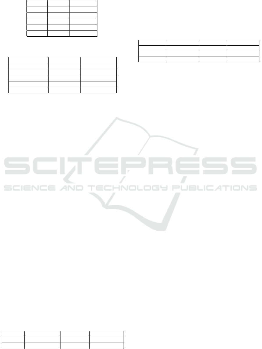
Table 6: State Pattern Instances Detected from the Execu-
tion Data of Synthetic Software Systems.
#4 #5
Context TContext Context
State TS State
setState setS() setState()
request request() writeName()
handle handle() write()
Table 7: Strategy Pattern Instances Detected from the Exe-
cution Data of Synthetic Software Systems.
#6 #7
Context RemoteControl TContext
State Command TS
setStrategy setCommand() setS()
contextInterface pressButton() contextInterface()
algorithmInterface execute() algorithmI()
Similarly, we executed DePaD tool by taking the
execution data collected from the six synthetic soft-
ware systems as input for state and strategy patterns,
two state pattern instances and two strategy pattern
instances were returned. Detailed information of the
detected state and strategy pattern instances are shown
in Tables 6-7. By manually inspecting these detected
pattern instances with respect to the domain know-
ledge, we found that (1) all detected state/strategy pat-
tern instances are valid; and (2) all state/strategy pat-
tern instances implemented in Synthetic 1, Synthetic
2, and Synthetic 4 were fully detected.
To validate the accuracy of the detection results,
we also manually analyzed the detected pattern in-
stances in terms of precision and recall. Table 8 re-
ports the precision and recall for observer, state and
strategy pattern instances detected from the synthetic
software execution data. According to the compari-
son, we conclude that the proposed approach does not
include false positives and can find all true positives
in case they are included in the execution data.
6.4 Evaluation based on Open-source
Software Systems
In this section, we report the evaluation of our appro-
ach using three open-source software systems. We
executed the DePaD tool by taking the software exe-
cution data as input, the number of detected observer,
state and strategy pattern instances are shown in Ta-
ble 9. By manually inspecting the detected pattern
Table 8: Precision and Recall of the Detected Pattern In-
stances from Synthetic Software Systems.
Observer Pattern State Pattern Strategy Pattern
Precision 100% 100% 100%
Recall 100% 100% 100%
instances, we found that all of them are valid, i.e., the
precision of our approach is 100%. This can be ex-
plained by the fact that our approach guarantees all
detected pattern instances satisfy both structural and
behavioral constraints.
Table 9: Number of Detected Pattern Instances from the
Execution Data of 3 Open-source Software Systems.
Observer Pattern State Pattern Strategy Pattern
Lexi 0.1.1 – – 8
JUnit 3.7 2 2 –
JHotDraw5.1 4 22 24
Note that – means no pattern instance is detected from the data.
7 THREATS TO VALIDITY
In the following, we discuss the main threats that may
affect the validity of our approach.
• Similar to other dynamic analysis techniques, the
quality of the proposed approach heavily depends
on the completeness of the execution data. If the
execution data do not cover fractions of the soft-
ware’s behavior including all pattern candidates,
the results would be unreliable.
• The precision and recall of the detection appro-
ach heavily rely on the design pattern specifica-
tion. On one hand, if the pattern specification is
over-defined (e.g., some unnecessary constraints
are included), this will cause low recall as some
true positives may be missing. On the other hand,
if the pattern specification is under-defined (e.g.,
some essential constraints are not included), this
will cause low precision as some false positives
may be incorrectly detected.
8 CONCLUSION
Existing dynamic analysis-based design pattern de-
tection approaches generally have problems in per-
forming accurate behavioral constraint checking and
providing extensible mechanism to support novel de-
sign patterns. This paper proposes a general frame-
work to support the detection of behavioral design
patterns from software execution data. To test the ap-
plicability, the framework was instantiated for three
typical behavioral design patterns, i.e., observer pat-
tern, state pattern and strategy pattern. In addition, the
proposed approaches have been implemented as a tool
in the open source process mining toolkit ProM. Cur-
rently, this tool supports observer pattern, state pattern
and strategy pattern. The applicability of this tool was
A Framework to Support Behavioral Design Pattern Detection from Software Execution Data
75

demonstrated by a set of software execution data con-
taining around 1 million method calls.
This work opens the door for several further rese-
arch directions. The detection of other typical crea-
tional and behavioral design patterns (e.g., singleton
pattern, factory method pattern, command pattern, vi-
sitor pattern) should be included in our framework.
In addition, we are working on analyzing large-scale
software projects and try to detect more design pattern
instances to evaluate the scability and empirically va-
lidate extensibility of the approach.
ACKNOWLEDGEMENTS
This work is supported by the NIRICT 3TU.BSR (Big
Software on the Run) research project
7
.
REFERENCES
Arcelli, F., Perin, F., Raibulet, C., and Ravani, S. (2009). Ja-
dept: Dynamic analysis for behavioral design pattern
detection. In 4th International Conference on Evalu-
ation of Novel Approaches to Software Engineering,
ENASE, pages 95–106.
Arcelli, F., Perin, F., Raibulet, C., and Ravani, S. (2010).
Design pattern detection in java systems: A dynamic
analysis based approach. Evaluation of Novel Appro-
aches to Software Engineering, pages 163–179.
Bernardi, M. L., Cimitile, M., De Ruvo, G., Di Lucca,
G. A., and Santone, A. (2015). Model checking to im-
prove precision of design pattern instances identifica-
tion in oo systems. In 10th International Joint Confe-
rence onSoftware Technologies (ICSOFT), volume 2,
pages 1–11. IEEE.
Bernardi, M. L., Cimitile, M., and Di Lucca, G. (2014).
Design pattern detection using a dsl-driven graph ma-
tching approach. Journal of Software: Evolution and
Process, 26(12):1233–1266.
Cong Liu, Boudewijn van Dongen, N. A. W. v. d. A. (2018).
A general framework to detect behavioral design pat-
terns. In International Conference on Software Engi-
neering (ICSE2018), pages 1–2. ACM.
Dabain, H., Manzer, A., and Tzerpos, V. (2015). Design
pattern detection using finder. In Proceedings of the
30th Annual ACM Symposium on Applied Computing,
pages 1586–1593. ACM.
De Lucia, A., Deufemia, V., Gravino, C., and Risi, M.
(2009a). Behavioral pattern identification through
visual language parsing and code instrumentation.
In Software Maintenance and Reengineering, 2009.
CSMR’09. 13th European Conference on, pages 99–
108. IEEE.
7
http://www.3tu-bsr.nl/doku.php?id=start
De Lucia, A., Deufemia, V., Gravino, C., and Risi, M.
(2009b). Design pattern recovery through visual lan-
guage parsing and source code analysis. Journal of
Systems and Software, 82(7):1177–1193.
Dong, J., Zhao, Y., and Sun, Y. (2009). A matrix-based
approach to recovering design patterns. IEEE Tran-
sactions on Systems, Man, and Cybernetics-Part A:
Systems and Humans, 39(6):1271–1282.
Fontana, F. A. and Zanoni, M. (2011). A tool for de-
sign pattern detection and software architecture recon-
struction. Information sciences, 181(7):1306–1324.
Gamma, E. (1995). Design patterns: elements of reusable
object-oriented software. Pearson Education India.
Heuzeroth, D., Holl, T., Hogstrom, G., and Lowe, W.
(2003). Automatic design pattern detection. In Pro-
gram Comprehension, 2003. 11th IEEE International
Workshop on, pages 94–103. IEEE.
Leemans, M. and Liu, C. (2017). Xes software event exten-
sion. XES Working Group, pages 1–11.
Liu, C., van Dongen, B., Assy, N., and van der Aalst, W.
(2016). Component behavior discovery from software
execution data. In International Conference on Com-
putational Intelligence and Data Mining, pages 1–8.
IEEE.
Ng, J. K.-Y., Gu
´
eh
´
eneuc, Y.-G., and Antoniol, G. (2010).
Identification of behavioural and creational design
motifs through dynamic analysis. Journal of Software
Maintenance and Evolution: Research and Practice,
22(8):597–627.
Niere, J., Sch
¨
afer, W., Wadsack, J. P., Wendehals, L., and
Welsh, J. (2002). Towards pattern-based design reco-
very. In Proceedings of the 24th international confe-
rence on Software engineering, pages 338–348. ACM.
Pettersson, N., Lowe, W., and Nivre, J. (2010). Evalu-
ation of accuracy in design pattern occurrence de-
tection. IEEE Transactions on Software Engineering,
36(4):575–590.
Shi, N. and Olsson, R. A. (2006). Reverse engineering
of design patterns from java source code. In 21st
IEEE/ACM International Conference on Automated
Software Engineering, 2006., pages 123–134. IEEE.
Tsantalis, N., Chatzigeorgiou, A., Stephanides, G., and Hal-
kidis, S. T. (2006). Design pattern detection using si-
milarity scoring. IEEE transactions on software engi-
neering, 32(11).
Von Detten, M., Meyer, M., and Travkin, D. (2010). Re-
verse engineering with the reclipse tool suite. In 2010
ACM/IEEE 32nd International Conference on Soft-
ware Engineering, volume 2, pages 299–300. IEEE.
Wendehals, L. and Orso, A. (2006). Recognizing behavioral
patterns atruntime using finite automata. In Procee-
dings of the 2006 international workshop on Dynamic
systems analysis, pages 33–40. ACM.
ENASE 2018 - 13th International Conference on Evaluation of Novel Approaches to Software Engineering
76
