
Overtaking Vehicle Detection Techniques based on Optical Flow and
Convolutional Neural Network
Lu-Ting Wu
1
and Huei-Yung Lin
2
1
Department of Electrical Engineering, National Chung Cheng University, 168 University Rd., Chiayi 621, Taiwan
2
Department of Electrical Engineering, Advanced Institute of Manufacturing with High-Tech Innovation,
National Chung Cheng University, 168 University Rd., Chiayi 621, Taiwan
Keywords:
Overtaking Vehicle Detection, ADAS, CNN.
Abstract:
As the rise of the intelligent vehicle applications in recent years, the development of onboard vision systems
for advanced driving assistance has become a popular research topic. This paper presents a real-time system
using a monocular camera mounted on the rear of a vehicle to perform overtaking detection for safe lane
change operations. In this work, the possible overtaking vehicle is first located based on motion cues. The
candidate is then identified using Convolutional Neural Network (CNN) and tracked for behavior analysis
in a short period of time. We also propose an algorithm to solve the issue of repetitive patterns which is
commonly appeared in the highway driving. A series of experiments are carried out with real scene video
sequences recorded by a dashcam. The performance evaluation has demonstrated the effectiveness of the
proposed technique.
1 INTRODUCTION
In the past few decades, advanced driving assistance
systems (ADAS) have achieved great advances. They
are commonly used to improve the driving safety and
traffic efficiency. Recently, the researches on advan-
ced driver assistance systems have gained a great mo-
mentum in vehicle safety issues. For examples, lane
departure warning system (LDWS), forward collision
warning system (FCWS), and lane change assistance
(LCA) are some typical applications of ADAS. At the
present, many high end vehicles are equipped with
ADAS directly from the original manufacturer. Some
traffic recorders in the after market such as Mobileye
660 (Mobileye, 2017) and Papago P3 (Papago, 2017)
are also equipped with various ADAS functions. The
driving recorder or dashcam not only records the traf-
fic conditions but also assists the driver to acquire the
traffic information (Dai et al., 2017). The main ob-
jective is to provide a safe and comfort driving expe-
rience.
There are many kinds of sensors used in advan-
ced driving systems such as radar, lidar, and visual
sensor, etc. Among them, the imaging technology
using visual sensor has the greatest progress potential
in recent years. The visual sensors become cheaper
and lighter than ever before. They can provide rich
sensing information of the environment and therefore
be used to design more functions for driving assis-
tance. Some examples include vehicle identification
(Liu et al., 2016), traffic sign recognition (Luo et al.,
2017; Shi and Lin, 2017), front collision warning (Lin
et al., 2012), parking assistance (Fernandez-Llorca
et al., 2014), vehicle speed detection (Lin et al., 2008),
and other applications. In the past few years, image
processing speed is also greatly improved because of
the use of graphics processor unit (GPU). The pro-
gress of this hardware makes the image processing
task rapid and more suitable for advanced driving as-
sistance systems.
Vehicle drivers usually assess the surrounding
traffic before changing lanes, and make turns after
checking their rear view and side mirrors. However,
even for those who follow the standard procedure, the
blind-zone of vehicles is still a source of danger and
often the cause of serious accidents. A blind-zone of a
vehicle can be described as “an area around the vehi-
cle that cannot be seen directly by the driver by look-
ing forwards or by using any of the vehicles standard
rear-view mirrors (internal and external) from the nor-
mal sitting position” (Hughes et al., 2009). According
to Taiwan Area National Freeway Bureau (MOTC,
2017), the main cause of major traffic accidents in the
state roads was the result of “improper conversion la-
Wu, L. and Lin, H.
Overtaking Vehicle Detection Techniques based on Optical Flow and Convolutional Neural Network.
DOI: 10.5220/0006698001330140
In Proceedings of the 4th International Conference on Vehicle Technology and Intelligent Transport Systems (VEHITS 2018), pages 133-140
ISBN: 978-989-758-293-6
Copyright
c
2019 by SCITEPRESS – Science and Technology Publications, Lda. All rights reserved
133
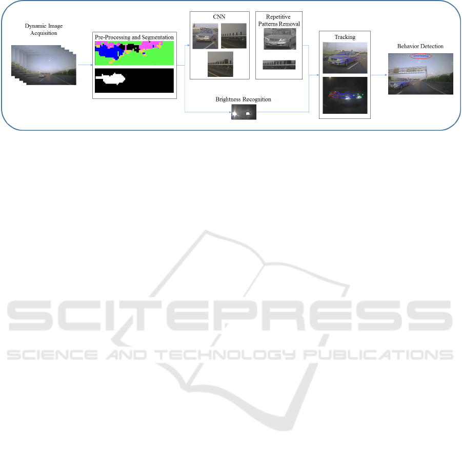
Figure 1: The system flowchart of the proposed overtaking detection technique. It consists of four basic modules: (1) pre-
processing and segmentation, (2) convolutional neural network, (3) repetitive pattern removal, and (4) tracking and behavior
detection.
nes” followed by “not paying attentions to the state in
front of the vehicle”.
In order to improve the driving safety, a dashcam
can be installed in the rear of the vehicle and used to
detect the blind-zone of the overtaking vehicles. It
is able to provide the necessary information for the
driver about the situation in advance, to avoid the
car accident due to an improper turn or lane change.
In this work, our experiments contain image sequen-
ces acquired from a variety of scenes during day and
night. To reduce the cost, a monocular camera is used
as the primary sensor. It is also a common approach
to analyze the traffic condition using a static camera
system.
Because of the vehicle motion and the dynamic
change of the scene, the development of onboard ca-
mera systems is not a trivial task in terms of the
operation efficiency and result accuracy. The image
sequence is constantly blurred due to the rapid mo-
vement of the vehicle, which introduces unwanted ar-
tifacts when the overtaking vehicles approach the ca-
mera. Furthermore, the limited field of view of the ca-
mera poses additional challenges on vehicle tracking.
The vehicle detection is generally more difficult in the
urban areas and at night. In the urban areas, the en-
vironment is complicated and the vehicles will have
various kinds of behavior to respond to. At night, in
additional to the complex environment, the image se-
quences also contain less information due to the il-
lumination condition. In most situations, the feature
used for the detection of overtaking vehicles is only
the headlights.
2 RELATED WORK
There are many general vehicle detection techniques
in the literature. For related work, we mainly sur-
vey the vision based approaches for vehicle overta-
king and blind-zone detection. The camera system for
image acquisition is commonly installed in the front,
rear, or sides of the vehicle. For the camera mounted
in the front, the overtaking detection is based on the
vehicle’s motion cues. The advantage of using mo-
tion cues is the operation speed. It can still lead to
good results even when the vehicle is only partially
visible due to occlusion or limited field of view of the
camera. Thus, a more complete and continuous tra-
jectory can be obtained. It is, however, easy to be
affected by noise and generates erroneous results.
In previous work, Hultqvistet et al. (Hultqvist
et al., 2014) and Chen et al. (Chen and Wu, 2015)
proposed efficiency detection overtaking algorithms
using optical flow. Their approaches have the came-
ras placed in the front of the vehicle. As a result, they
cannot notify the driver about the occurrence of over-
taking in advance. Alonso et al. (Alonso et al., 2008)
presented a blind-zone overtaking vehicle detection
system using optical flow with the cameras installed
below the side-view mirror. Wu et al. (Wu et al.,
2012) proposed an embedded blind-zone security sy-
stem with a camera mounted below the side-view mir-
ror. First, they detect low-features such as shadows,
edges and headlights to locate the vehicle, followed
by vehicle tracking and behavior analysis. The came-
ras below the side-view mirror can detect overtaking
vehicles better than others in the blind-zone. Howe-
ver, it requires a pair of cameras which are installed
in per external rear mirror and the functions of the ca-
meras are limited than other approaches.
There also exist some techniques with a camera
mounted in the rear of the vehicle to detect the over-
taking in the blind-zone. It is not only used to inform
the driver in advance, but also used by other advan-
ced driving assistance functions. For example, the
parking collision avoidance system can use the rear
camera to detect the obstacles in the back to avoid
collision. Dooley et al. (Dooley et al., 2016) installed
VEHITS 2018 - 4th International Conference on Vehicle Technology and Intelligent Transport Systems
134
a fisheye camera in the rear of the vehicle, and used
the AdaBoost classification technique and two wheel
detection methods to identify the blind-zone vehicles.
The vehicles were then tracked by the optical flow
technique. Ramirez et al. (Ramirez et al., 2014) in-
stalled cameras in the front and the rear of the vehi-
cle. They used Deformable Parts Model (DPM) (Pan-
dey and Lazebnik, 2011) to combine optical flow with
the mobile information to detect the overtaking vehi-
cles. According to their experimental results, combi-
ning these two methods they were able to increase the
accuracy of the detection compared to the use of an
appearance detector.
3 PROPOSED METHOD
In this paper, we propose a real-time system that uses
a monocular camera mounted in the rear of a vehicle
to detect overtaking and assist the driver to change la-
nes. The monocular camera is installed at the height
of about 1 meter from the ground. In our main met-
hod the architecture contains (1) pre-processing and
segmentation, (2) convolutional neural network, (3)
repetitive pattern removal, and (4) tracking and beha-
vior detection, as illustrated in Figure1.
3.1 Pre-Processing and Segmentation
In order to increase the speed of operations, we usu-
ally use only about half size of the original image by
removing unnecessary regions such as the sky, buil-
dings or traffic signs located in the upper part of the
image. Thus, the region of interest (ROI) is first de-
fined before performing the image segmentation al-
gorithm. To obtain the motion clues in an image,
the settings on the tracking points are very important.
Chen et al. (Chen and Wu, 2015) use Canny edge de-
tection to extract the edges in the image, and then use
the optical flow to calculate the edges of the motion
clues. Ramirezet et al. (Ramirez et al., 2014) detect
the strong corners, and then use the optical flow to
calculate the corners of the motion clues. Although
using edges or corners as tracking features can derive
more robust results, it may increase the amount of ex-
tra computations. Further, it is hard for us to deter-
mine the number of tracking feature when the image
is complicated, which will also cause the uncertainty
of computing time.
To avoid the above problems, we set a fixed num-
ber of tracking points in a fixed location. First, we set
a tracking point per 10× 10 pixels in an ROI. Second,
we use the pyramid model of Lucas-Kanade optical
flow (Lucas and Kanade, 1981) to calculate the op-
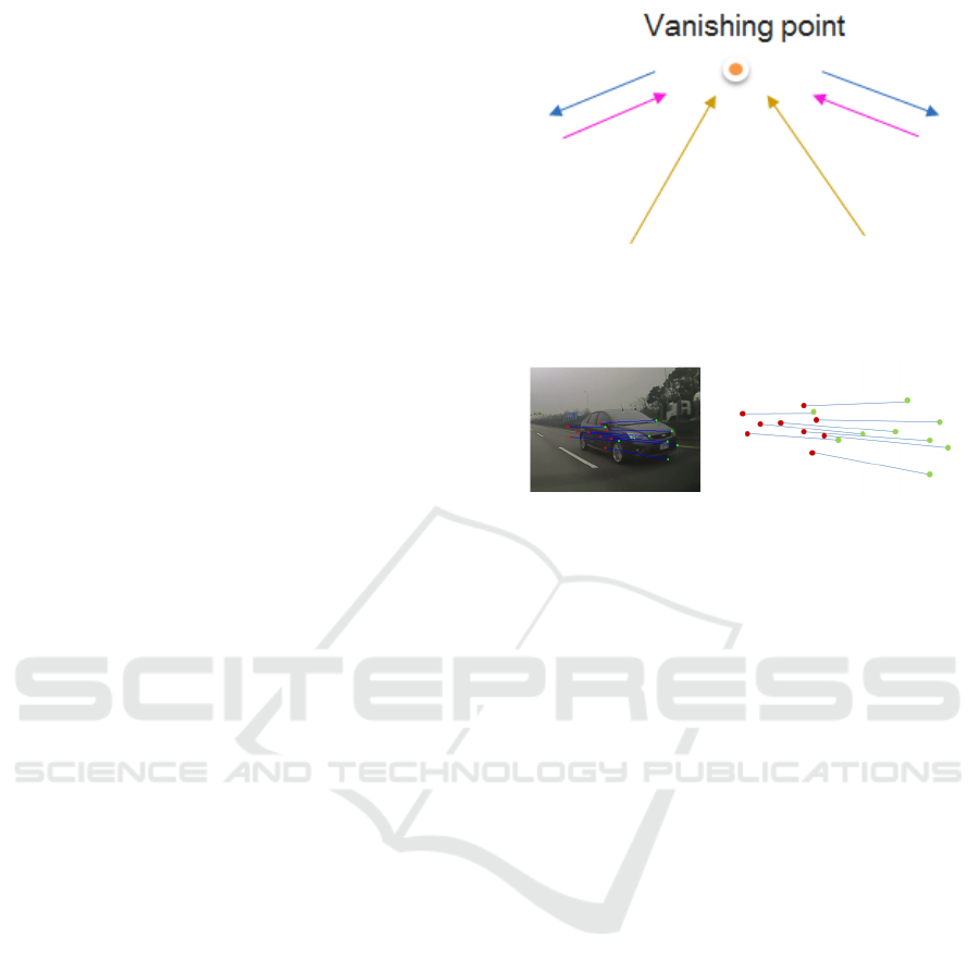
Figure 2: Directional classification diagram. The yellow
lines represent the land marking. The blue lines illustrate
the objects (vehicles) approaching from the sides. The pink
lines illustrate the objects (vehicles) moving further away.
Figure 3: The optical flow in the x-direction.
tical flow information of the tracking points. Third,
according to the direction and measurement of the
tracking output, we divide it into five different cate-
gories: (i) road and sky, (ii) land marking, (iii) over-
taking vehicle, (iv) object further away, (v) uncertain
region.
When a vehicle is moving forward, there will be a
large amount of optical flow around the vehicle. Ho-
wever, the road and sky are relatively smooth, and the
optical flow is small. Therefore, if the optical flow of
a feature point is very small, we can assign the point
to the road and sky region. If the optical flow in the
y-direction is very large and moves to the vanishing
point, then the point is assigned to the land marking.
The points are considered as the overtaking vehicle
if the optical flow in the x-direction is large and mo-
ves far away from the vanishing point. Otherwise,
if the optical flow in the x-direction is large and mo-
ves towards the vanishing point, it indicates that some
object is moving further away. These conditions are
illustrated in Figure 2. We use the uncertain region to
conclude the situations not in one of the above crite-
ria.
Here we only use the x-direction of the optical
flow to distinguish the overtaking vehicle from the ob-
ject moving further away, and discard the y-direction
of the optical flow. The main reason is that the y-
direction of the optical flow in two adjacent frames is
very small, and the approaching vehicle will be de-
formed (see Figure3). Thus, it is difficult to use the
y-direction of optical flow to distinguish the direction
of the object motion.
Overtaking vehicles are continually approaching,
Overtaking Vehicle Detection Techniques based on Optical Flow and Convolutional Neural Network
135
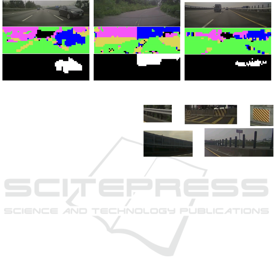
(a) (b) (c)
Figure 4: The accumulation of tracked points and image segmentation used to detect the approaching vehicles.
so the space correlation between two vehicles is used
to filter out the noise. We accumulate every tracking
point of the approaching object to a grayscale image
and binarize it. Then, a 10 × 10 mask is used to dilate
each tracking point, to make a connection between the
points, and filter out the small connection areas. An
illustration of these rules is shown in Figure 4(a). The
top is the original image, the middle is the result of
a single frame, and the bottom is the binarized result
from multiple frames.
When the vehicle makes turns or there are repe-
titive patterns in the image, the segmentation results
might not be correct, as illustrated in Figures 4(b) and
4(c) respectively. In the urban area, there are a va-
riety of curved roads. This makes the vehicle move
in a more complicated way, so the optical flow of
the rear objects and background will be away from
the vanishing point. Another common problem is the
repetitive patterns in the images. When a vehicle is
in fast motion, another image point close to the ori-
ginal image point might be identified as the original
image point. With this continuous appearance, a re-
petitive pattern will be generated and false targets will
be tracked by the optical flow algorithm. Since the re-
petitive patterns usually appear for a period of time in
the same image region, it is difficult to filter out the
wrong features using the spatio-temporal correlation
of the image pixels. Figure 5 shows some repetitive
patterns commonly seen in Taiwan’s highway and lo-
cal road. To deal with this problem, we use the convo-
lutional neural network to identify the segmented area
and remove the non-vehicle objects to avoid the false
segmentation to produce false positives.
3.2 Convolutional Neural Network
The convolutional neural network architecture used in
this work is CaffeNet (BLVC, 2017). It is a replica-
tion of the model described in the AlexNet publica-
Figure 5: Common repetitive patterns in Taiwan.
tion (Krizhevsky et al., 2012) but with some differen-
ces. This network was originally designed to clas-
sify 1000 different categories of objects in the Ima-
geNet database. We performed fine-tuning using our
data in BVLC CaffeNet model and changed the out-
put to 6 categories. It contains the front of the car,
the rear of the car, the motorcycle, repetitive patterns,
background and lane marks. Some of the images are
shown in Figure 6. The images are segmented by the
algorithm described in Section 3.1. The deep learning
framework, Caffe (Jia et al., 2014), is used to train
and evaluate the neural network. We added CaffeNet
to our system to identify the segmented area and re-
move the non-vehicle objects.
3.3 Repetitive Pattern Removal
In some situations, wrong segmentation, especially
when the algorithm is confused with a vehicle on the
opposite lane. As a result, the segmentation and CNN
identification are erroneous at the same time. This
kind of error is due to the feature points of the opti-
cal flow tracking on the repetitive patterns, but CNN
recognizes the vehicle in the opposite lane. One such
example is shown in Figure 7. To solve this problem,
we consider the case that a moving vehicle is in the
opposite lane and the repeated pattern occurs due to
the separation poles. As shown in Figure 8, they make
the optical flow disorder, resulting in forward and bac-
kward optical flow inconsistency.
VEHITS 2018 - 4th International Conference on Vehicle Technology and Intelligent Transport Systems
136
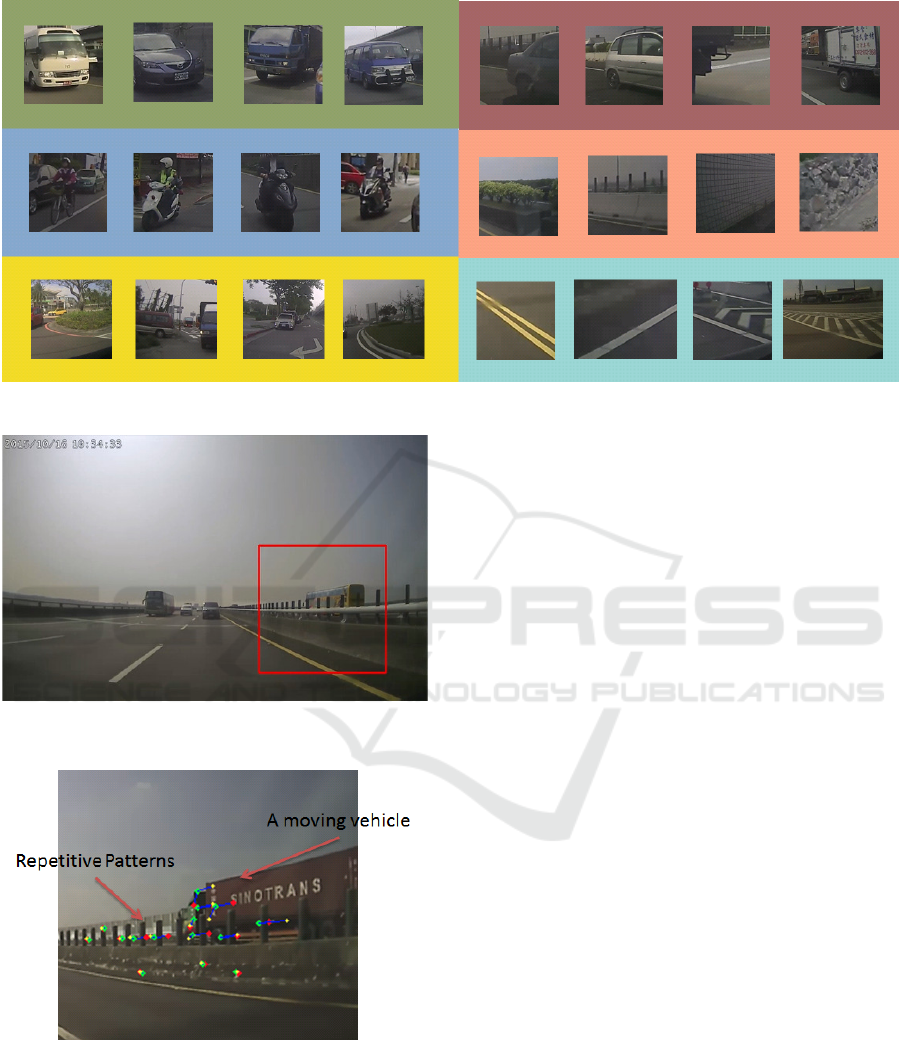
Figure 6: Some sample images in the training data used in this work.
Figure 7: The use of segmentation and CNN at the same
time can still be erroneous for repetitive patterns.
Figure 8: An illustration of messy optical flow when repeti-
tive patterns occur.
We use multiple feature points to determine whet-
her the segmented region contains repetitive patterns.
First, “good features to track” is used to detect the fea-
ture point P(t) on the frame at time t (Shi and Tomasi,
1994). Then, its succeeding P(t + 1) is found by re-
ferring to the forward optical flow f
+
t
= (u
+
, v
+
) from
the frame at t to the frame at t + 1. That is,
P(t + 1) = P(t) + f
+
t
(P(t))
Similarly, generated from the backward tracking,
the point P
0
(t) is related by the backward motion,
P
0
(t) = P
0
(t + 1) + f
−
t+1
(P
0
(t + 1))
where f (t +1)
−
= (u
−
, v
−
)
(
t +1) is the backward op-
tical flow from the frame at t + 1 to the frame at t.
Ideally, if the feature point P(t) does not belong
to a repetitive pattern and the optical flow is correctly
estimated, then we have
P(t) − P
0
(t) = 0
However, from our experience, there are some errors
in the real situations, i.e.,
P(t) − P
0
(t) ≤ ε
where ε is the error between P(t) and P
0
(t), and is
very small. If most of the feature points on the target
are within ε, we will classify this object as a vehicle.
Otherwise, it is classified as a repetitive pattern and
thus eliminated.
3.4 Tracking and Behavior Detection
After the segmentation using CNN and the repetitive
pattern removal, we track the object rather until it di-
sappeared in the image or no overtaking. Continue
the previous step of “repetitive pattern removal” and
the detection of feature points, we use Lucas-Kanade
optical flow for continuously tracking in order to
• detect the movement of objects for a period of
time,
Overtaking Vehicle Detection Techniques based on Optical Flow and Convolutional Neural Network
137
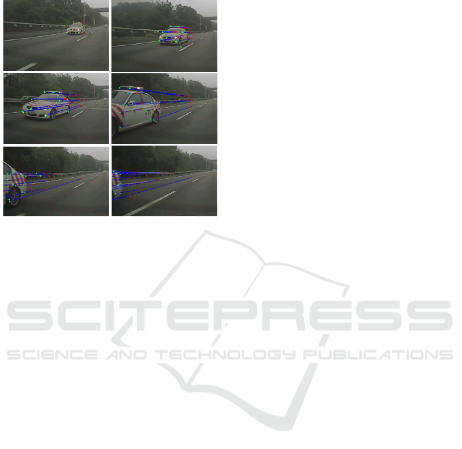
Figure 9: An example result of the overtaking vehicle de-
tection and tracking.
• overcome the shape, size and scale of the object
changes as it approaches the camera,
• get the operation speed quickly,
• have a more complete trajectory which can be pro-
vided at the edge or part of the field.
A tracking result is shown in Figure9.
We expect that CNN is able to identify and remove
the repetitive patterns, and have the correct overtaking
detection. However, the camera resolution is too low,
and the image segmentation is not good enough for
identification due to some errors. To further reduce
the false detection, we assess whether the direction of
tracking has continued to stay away from the vanis-
hing point for a period of time to help us effectively
remove the wrong detection.
3.5 Night Time
In general, the appearance of the vehicle at night can-
not be clearly obtained from the camera because the
brightness of the image is too low. The camera usu-
ally captures the information of the headlights. If only
the brightness is used to grab the headlights, it can be
easily disturbed by other background lights. Further-
more, the headlights of the vehicles in the sides do not
have the symmetry property, which makes the overta-
king detection at night a difficult issue.
We present a method that uses motion cues to
combine the brightness information to capture the
overtaking vehicles. The steps of overtaking detection
at night includes: (1) pre-processing and segmenta-
tion, (2) brightness recognition, (3) tracking, and (4)
behavior detection. First, we use ROIs to remove the
image regions which are not important. Second, the
headlight areas are segmented when they approach
the vehicle by the algorithm described in Section 3.1.
Figure 10 shows a typical result. Third, the low brig-
htness areas are removed by binarization. Finally, we
track the brightness region and analyze its behavior
by the method given in Section 3.4. If it continues to
keep away from the vanishing point, it is considered
as the headlights of an overtaking vehicle.
4 IMPLEMENTATION AND
EXPERIMENTAL RESULTS
To evaluate the performance of our overtaking de-
tection method in the real world scenarios, we use
a dashcam to capture the dynamic images. Our
dashcam is installed in the rear of the vehicle at about
1 meter about ground. The original image size is
1200 × 800, and the sub-image region for process
is 600 × 200. We test our algorithms on a PC with
ubuntu 16.04 operating system, 4.0 GHz Intel CPU,
and ASUS GTX 1080 GPU. The execution time is di-
vided into three parts tabulated in Table 1.
There are totally 7,587 images collected in our
training data. The image sequences are segmented
using the algorithm described in Section 3.1 and mar-
ked manually for each image. Similarly, the vali-
dation data of 2,770 images are collected from 80-
minute video sequence and marked manually. The
recognition results for each category are tabulated in
Table 2. In our vehicle recognition module, it does
not matter if overtaking is identified or not since a
subsequent tracking stage will be performed. Howe-
ver, a serious false alarm will occur if the background
is recognized as overtaking. This usually happens
when making turns with a vehicle in the background
as shown in Figure 11.
It is not easy to evaluate the accuracy and effi-
ciency of the real image sequence at the present time.
In particular, the algorithms for detecting vehicles by
motion cues do not have good benchmarks for perfor-
mance evaluation. There are totally 50 image sequen-
ces collected in our database. It contains 20 highway
image sequences, 15 city image sequences and 15
night image sequences. Each image sequence is about
two minutes. If we detect the vehicle before it is di-
sappeared in the image sequence, the overtaking de-
tection is successful. Otherwise, it is called missed.
It is considered as failed if the approaching vehicle is
not detected. The evaluation is tabulated in Table 3
and some result images are shown in Figure 12.
VEHITS 2018 - 4th International Conference on Vehicle Technology and Intelligent Transport Systems
138
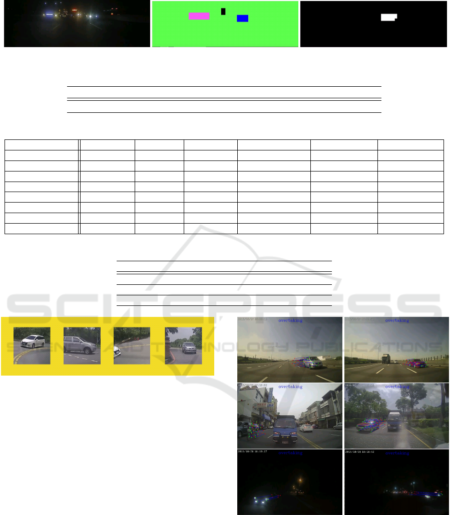
Figure 10: Overtaking vehicle detection and tracking at night using the headlights.
Table 1: The execution time for individual stages of the algorithm.
Segmentation CNN Repetitive Patterns Removal Entire Time
time 6ms 3ms 1ms 6-10ms
Table 2: The recognition results for each category and the recall.
Background Lane mark Locomotive Repetitive pattern Front of vehicle Back of vehicle
Groundtruth 375 252 545 408 480 710
Background 322 1 2 0 1 11
Land mark 2 249 0 2 0 0
Locomotive 0 0 524 1 0 0
Repetitive pattern 25 2 0 405 0 3
Front of vehicle 13 0 16 0 470 34
Rear of vehicle 13 0 3 0 9 662
Recall 0.858 0.988 0.961 0.992 0.979 0.932
Table 3: The experimental results and performance evaluation.
Scene True overtakes Detected Missed False
City 102 102 0 13
Highway 79 79 0 1
At night 42 37 5 4
Figure 11: The false alarm might happen if the vehicle ma-
kes turns with another behind.
5 CONCLUSIONS
This paper presents a real-time system to detect over-
taking and assist in driving lane change based on vi-
sual cues from a dashcam . We use the motion cues
and combine with CNN to detect the vehicle appea-
rance. Compared to the low-order features and weak
classifier it is faster and more robust. It is more sui-
ted for light and complex environments. In addition
to improving the limitation and shortcomings of the
existing methods, the proposed technique can main-
tain the operational efficiency and provide more com-
plete overtaking information. The performance eva-
luation has demonstrated the effectiveness of the pro-
posed techniques.
Figure 12: Some overtaking vehicle detection results. High
traffic, local traffic and night are shown in the top, middle,
and bottom, respectively.
ACKNOWLEDGMENTS
The support of this work in part by Create Electronic
Optical Co., LTD, Taiwan and the Ministry of Science
Overtaking Vehicle Detection Techniques based on Optical Flow and Convolutional Neural Network
139

and Technology of Taiwan under Grant MOST 104-
2221-E-194- 058-MY2, is gratefully acknowledged.
REFERENCES
Alonso, J. D., Vidal, E. R., Rotter, A., and Muhlenberg,
M. (2008). Lane-change decision aid system based on
motion-driven vehicle tracking. IEEE Transactions on
Vehicular Technology, 57(5):2736–2746.
BLVC (2017). CaffeNet. https://github.com/BVLC/caffe/
tree/master/models/bvlc reference caffenet.
Chen, Y. and Wu, Q. (2015). Moving vehicle detection
based on optical flow estimation of edge. In 2015
11th International Conference on Natural Computa-
tion (ICNC), pages 754–758.
Dai, J. M., Liu, T. A. J., and Lin, H. Y. (2017). Road sur-
face detection and recognition for route recommenda-
tion. In 2017 IEEE Intelligent Vehicles Symposium
(IV), pages 121–126.
Dooley, D., McGinley, B., Hughes, C., Kilmartin, L., Jo-
nes, E., and Glavin, M. (2016). A blind-zone de-
tection method using a rear-mounted fisheye camera
with combination of vehicle detection methods. IEEE
Transactions on Intelligent Transportation Systems,
17(1):264–278.
Fernandez-Llorca, D., Garcia-Daza, I., Martinez-Hellin, A.,
Alvarez-Pardo, S., and Sotelo, M. A. (2014). Par-
king assistance system for leaving perpendicular par-
king lots: Experiments in daytime/nighttime conditi-
ons. IEEE Intelligent Transportation Systems Maga-
zine, 6(2):57–68.
Hughes, C., Glavin, M., Jones, E., and Denny, P. (2009).
Wide-angle camera technology for automotive appli-
cations: a review. IET Intelligent Transport Systems,
3(1):19–31.
Hultqvist, D., Roll, J., Svensson, F., Dahlin, J., and Schn,
T. B. (2014). Detecting and positioning overtaking
vehicles using 1d optical flow. In 2014 IEEE Intel-
ligent Vehicles Symposium Proceedings, pages 861–
866.
Jia, Y., Shelhamer, E., Donahue, J., Karayev, S., Long, J.,
Girshick, R., Guadarrama, S., and Darrell, T. (2014).
Caffe: Convolutional architecture for fast feature em-
bedding. In Proceedings of the 22Nd ACM Internati-
onal Conference on Multimedia, MM ’14, pages 675–
678, New York, NY, USA. ACM.
Krizhevsky, A., Sutskever, I., and Hinton, G. E. (2012).
Imagenet classification with deep convolutional neu-
ral networks. In Proceedings of the 25th Internatio-
nal Conference on Neural Information Processing Sy-
stems, NIPS’12, pages 1097–1105, USA. Curran As-
sociates Inc.
Lin, H. Y., Chen, L. Q., Lin, Y. H., and Yu, M. S. (2012).
Lane departure and front collision warning using a
single camera. In 2012 International Symposium
on Intelligent Signal Processing and Communications
Systems, pages 64–69.
Lin, H.-Y., Li, K.-J., and Chang, C.-H. (2008). Vehicle
speed detection from a single motion blurred image.
Image Vision Comput., 26(10):1327–1337.
Liu, X., Liu, W., Mei, T., and Ma, H. (2016). A deep
learning-based approach to progressive vehicle re-
identification for urban surveillance. In Leibe, B.,
Matas, J., Sebe, N., and Welling, M., editors, Compu-
ter Vision - ECCV 2016 - 14th European Conference,
Proceedings, Part II, volume 9906 of Lecture Notes in
Computer Science, pages 869–884. Springer.
Lucas, B. D. and Kanade, T. (1981). An iterative image re-
gistration technique with an application to stereo vi-
sion. In Proceedings of the 7th International Joint
Conference on Artificial Intelligence - Volume 2, IJ-
CAI’81, pages 674–679, San Francisco, CA, USA.
Morgan Kaufmann Publishers Inc.
Luo, H., Yang, Y., Tong, B., Wu, F., and Fan, B. (2017).
Traffic sign recognition using a multi-task convolutio-
nal neural network. IEEE Transactions on Intelligent
Transportation Systems, PP(99):1–12.
Mobileye (2017). Mobileye 660. http://
www.mobileye.com/.
MOTC (2017). Taiwan Area National Freeway Bureau,
MOTC. http://www.freeway.gov.tw/.
Pandey, M. and Lazebnik, S. (2011). Scene recognition and
weakly supervised object localization with deforma-
ble part-based models. In 2011 International Confe-
rence on Computer Vision, pages 1307–1314.
Papago (2017). Papago P3. http://www.papago.com.tw/.
Ramirez, A., Ohn-Bar, E., and Trivedi, M. (2014). Inte-
grating motion and appearance for overtaking vehicle
detection. In 2014 IEEE Intelligent Vehicles Sympo-
sium Proceedings, pages 96–101.
Shi, J. and Tomasi, C. (1994). Good features to track. In
1994 Proceedings of IEEE Conference on Computer
Vision and Pattern Recognition, pages 593–600.
Shi, J.-H. and Lin, H.-Y. (2017). A vision system for traffic
sign detection and recognition. In 2017 IEEE Inter-
national Symposium on Industrial Electronics, pages
1596–1601.
Wu, B. F., Kao, C. C., Li, Y. F., and Tsai, M. Y. (2012).
A real-time embedded blind spot safety assistance sy-
stem. International Journal of Vehicular Technology,
2012:1–15.
VEHITS 2018 - 4th International Conference on Vehicle Technology and Intelligent Transport Systems
140
