
Designing BP-IS Aligned Models: An MDA-based Transformation
Methodology
Wiem Khlif
1
, Nourchene Elleuch
2
, Enaam Alotabi
2
and Hanêne Ben-Abdallah
1,2
1
Mir@cl Laboratory, University of Sfax, Sfax, Tunisia
2
King Abdulaziz University, Jeddah, K.S.A.
Keywords: BPMN Model, MDA, Class Diagram, CIM-to-PIM Transformation, Business Context.
Abstract: The necessity of aligning an enterprise’s IS model to its business process model (BPM) is irrefutable. How
to ensure the establishment and/or maintenance of this alignment remains, however, a pressing need for
enterprises seeking to establish a new IS, better govern its enterprise architecture, and/or update its existing
IS face to business-driven changes. The main difficulty of establishing/maintaining BP-IS models alignment
stems from the divergent knowledge domains of the stakeholders (business process experts and software
developers). To bridge the gap between these two stakeholders, this paper proposes an MDA compliant
approach to automate the generation of UML class diagrams from BPMN models. The generated IS design
can be used either to establish a new IS system, or analyze or maintain an existing one. The generation is
defined in terms of transformations that ensure the alignment of the class diagram to the BPMN model by
both accounting for the semantics and structure of the BPMN model, and providing for all business objects
and activities.
1 INTRODUCTION
Each enterprise needs to have a clear vision of its
business processes in order to increase both the
quality of its products/services and its profits. To
fulfill this need, many enterprises adopt methods, and
tools to analyze their business processes. In addition,
to facilitate the management of the data manipulated
by its business process (BP) activities, a company
relies on an Information System (IS). As such, an
organization ends up perceived through two models:
a business process model that is used by business
managers, and an information system model that is
used by software/IT managers. The alignment of
these models is key to the success of a coherent
governance of the enterprise (Aversano et al., 2016).
In this context, the question is how to generate
and/or maintain the alignment between the IS and BP
models? This question has been tackled within two
scenarios. The first scenario aims either to establish a
mapping approach between an existing IS and BP
(Archimate, 2013) (Aversano et al., 2016), or to
analyze the impact of BP changes on its IS (Rostami
et al., 2017). It provides for the evaluation, control,
measurement and improvement of existing process
structures. The second scenario aims to extract/derive
requirements/design from BP models, e.g., (Rhazali
et al., 2016) (Cruz et al., 2012), (Meyer et al., 2013).
In this paper, we focus on the second scenario
while offering a means for applying the first scenario:
We propose a model-driven approach to automate the
generation of the IS model from the BP model. On the
one hand, our approach can be used to generate a new
IS model that is aligned with the source BP model.
On the other hand, its generated IS model can be used
to identify the links between the existing IS model
and a restructured BP model.
More specifically, we present an MDA-compliant
approach (OMG, 2006), called DESTINY (a moDel-
driven process aware requiremenTs engineerINg
methodologY). The main aim of DESTINY is to
automate the generation of an IS design represented
through a UML use case diagram (Jammal et al.,
2017) and, in this paper, a UML class diagram (a PIM
of the IS system) from a BP model described in the
standard BPMN notation (ISO/IEC 19510, 2013) (a
CIM of the IS system). The generation is defined as
transformations that ensure the alignment of the class
diagram with the BPMN model by both accounting
for the semantics and structure of the BPMN model
and providing for all business objects and activities.
258
Khlif, W., Elleuch, N., Alotabi, E. and Ben-Abdallah, H.
Designing BP-IS Aligned Models: An MDA-based Transformation Methodology.
DOI: 10.5220/0006704302580266
In Proceedings of the 13th International Conference on Evaluation of Novel Approaches to Software Engineering (ENASE 2018), pages 258-266
ISBN: 978-989-758-300-1
Copyright
c
2019 by SCITEPRESS – Science and Technology Publications, Lda. All rights reserved

Furthermore, the transformations have the merit of
generating class diagrams that respect well-known
quality metrics and UML design practices.
Overall, compared to existing works, our
approach contributes to the BP-IS alignment and IS
design domains by proposing semantic and structural
transformation rules that aim to obtain the class
diagram.
The remainder of this paper is structured as
follows: Section 2 discusses works related to aligning
BPM to IS model (e.g., requirements engineering and
data model). Section 3 gives a bird’s eye on
DESTINY whose components are detailed in the
following two sections; Section 4 presents the
business context of a BPMN model to identify
semantic information associated to BPMN elements.
Section 5 shows the transformation rules to generate
a class diagram from a BPMN model annotated with
its business context. Section 6 illustrate the
applicability of our method based on a case study.
Finally, Section 7 summarizes the presented work and
outlines its extensions.
2 RELATED WORK
This section presents state-of-the-art approaches that
focus on aligning BPM to IS model.
Cruz et al. (Cruz et al., 2012) study mainly the usage
and data persistence in BPMN 2.0. They propose an
approach to generate a data model from the business
process model. Then, the data model may be used as
a starting artifact in the IS software development
process. To do so, they propose three groups of rules:
The first group determines the data model entities.
Then, the second group defines the relationships
between them. Finally, the third group enumerates the
entities’ attributes. The proposed rules are neither
formalized nor validated.
Rhazali et al. (Rhazali et al., 2016) use ATL to
specify CIM-to-PIM transformations that structure
the produced class diagram according to the model
view controller (MVC) architectural style pattern.
The approach presented by De La Vara et al. (De
la Vara et al., 2009) proposes guidelines to extract the
domain class diagram from an extended version of
BPMN 1.2. Furthermore, the authors focus on
annotated data objects to allow data dependency
representation and data instance differentiation as
well as SQL queries generation (Meyer et al., 2013).
(Przybyłek, 2014) combine techniques from both the
fields of Business Process Engineering and
Requirements Engineering and define a Business-
oriented approach to requirements elicitation. This
approach allows to derive system requirements from
business process models. It enables traceability
between business processes and the corresponding
system requirements. This ensures that system
requirements meet real business needs and that there
are no superfluous requirements.
Overall, the above works related to BP-IS models
alignment rely on either the structural and/or semantic
information. The set of transformation rules defined
in (Meyer et al., 2013) (Rhazali et al., 2016) are
purely structure-based; it ignores the remaining
aspects of a BP, which do affect the performance of a
BP. For example, the type of semantic relations
between classes is not captured, like the composition,
heritage, etc. Our proposed method combines both
aspects in order to obtain a class diagram that covers
the structural aspect. Furthermore, our proposed set
of transformation rules complements existing ones
with rules to deal with the organizational and
behavioral aspects of the BP model. To do so, they
use the concept of business context (see Section 4).
3 OVERVIEW ON DESTINY
DESTINY (a moDel-driven procESs-aware
requiremenTs engineerINg methodologY) is a
method that improves the IS design effectiveness and
reduces the risk of creating a model that does not
correspond to business needs and expectations. More
specifically, it derives the use case diagram from a
given BPMN model (Jammal et al., 2017). In this
paper, we complement the proposed methodology by
generating the class diagram representing IS model
(PIM) from a business process model (CIM) that is
supposed to be representative of the real world of the
enterprise. Towards this end, DESTINY accounts for
both the structural and semantic perspectives of both
models.
We designed DESTINY according to the MDA
four-layer meta-modeling architecture:
M0 (Reality Layer) contains a runtime
representation of models: the business
processes, the information system, and our
developed tool.
M1 (Model Layer) defines, with a concrete
syntax, the conceptual and transformation
models: In this layer, the CIM encapsulates the
business information in terms of a BPMN
model; the PIM specifies the static view such
as a static diagram (class and component
diagrams); and the pattern-based transforma-
tion model (TM) is used to generate the PIM
Designing BP-IS Aligned Models: An MDA-based Transformation Methodology
259
from the CIM by considering the syntax and
semantics of the modelling languages. Note
that the transformation from the CIM to the
PIM modeling language calls for using pattern-
based transformations.
M2 (Meta-Model Layer) contains the meta-
models which serve as an abstract syntax to
define the models of M1: The BPMN meta-
model (ISO/IEC 19510, 2013) to describe the
CIM, the UML metamodel (OMG-UML,
2015) to specify the PIM.
M3 (Meta-Meta-Model Layer) where all meta-
models of the previous layer are conforming to
MOF (OMG-MOF, 2015).
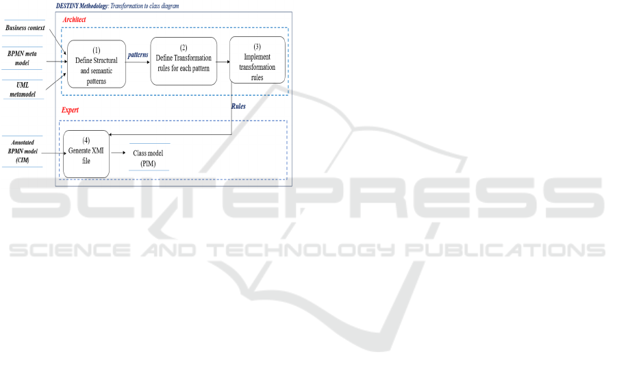
Figure 1: DESTINY for BP to IS (CIM to PIM)
transformation.
Figure 1 illustrates the DESTINY method for
CIM-to-PIM transformation based on the semantic
and structural information.
In an MDA-compliant approach, the CIM-PIM
transformation operates at the meta-model level.
However, the 1:1 mapping between the CIM and PIM
meta-model elements is not sufficient to preserve the
semantics of neither the business domain nor the
modeling languages. To overcome this deficiency,
the software architect identifies and enumerates, at
the meta-model level, a set of patterns that respect the
semantics of both the source and target languages
(BPMN model and structural diagrams, respectively)
as well as the semantics of the business domain.
Then, the software architect formalizes/implements
the transformation rules, which provides for the
automated generation of the PIM model. Finally, the
software designer applies the rules to generate the
class diagram from the BPMN model which is
annotated with its business context.
4 BUSINESS CONTEXT
DEFINITION
We define a business context for each BPMN element
to classify the encoded semantic information taking
into account four business process perspectives,
which are functional, informational, organizational,
and behavioral.
4.1 Functional and Informational
Perspectives based Semantics
The functional perspective represents the process
elements being performed. The central BPMN
concept that best reflects the functional perspective is
the Activity. An activity can be simple, which
represents a task, or composed that represents a sub-
process.
We enhance each activity with a business context that
contains the following information.
a. Lane ID is the unique identifier of the lane,
which contains the activity.
b. Upstream and downstream ID is the unique
identifier of the activity on which this activity
directly depends.
c. Extended attributes describe the activity
properties. Each attribute can be a pure value or
a complex one representing a business entity.
This distinction is extracted from their
description.
d. Activity Description indicates the relationships
between the business entities and/or the
activity’s extended complex attributes. The
relationships’ semantic follows these linguistic
patterns: BusinessObject + VerbalGroup +
Quantifiers +BusinessObject. The verbal
group indicates the relation type. In fact, the
verbal group “is entirely made of” or “is part
of” expresses an aggregation relationship
between the business objects. The verbal group
“is composed of” designates a composition
relation or “Is a” indicates the generalization/
specialization relation. If the verbal group
doesn’t belong to this set of keywords or any
synonyms, then it specifies an association
between the business objects. The quantifiers
are used to determine the multiplicity.
e. Resources are the data objects/stores that are
required by an activity to fulfill its goal. The
resources are described in terms of name,
extended attributes, and description. The data
objects/ stores’ extended attributes and
ENASE 2018 - 13th International Conference on Evaluation of Novel Approaches to Software Engineering
260
description have the same semantic than the
activity’s extended attributes and description.
Note that because the data represents the
informational perspective, then the resources needed
by an activity express semantic information related to
this perspective.
4.2 Organizational Perspective based
Semantics
The organizational perspective represents where and
by whom process elements are performed. The main
concepts in BPMN that reflects the organizational
perspective are Pool and Lane. Hence, in this
perspective, the context is associated to the lane
element. It describes the following information:
a. Lane/Pool ID is the unique identifier of the
lane/pool.
b. Lane/Pool Label should be significant.
c. Lane Description (respectively Pool
Description) indicates the semantic relation
between the lane (respectively pool) and the
tasks/data object or stores (respectively the
lanes or tasks/data object or stores) that
belong to it. This semantics respects the
same linguistic pattern defined in section
4.1.e.
d. Extended attributes describe the lane/pool
properties. As the activity extended
attributes, each one can be a pure value or
complex.
5 FROM BPMN TO CLASS
DIAGRAM
To consider the business context and facilitate the
transformation definition and automation, we lightly
extended the BPMN meta-model. However, we used
the UML metamodel without any adaptation or
modification. In this section, after presenting the
BPMN metamodel extension, we describe the
transformation rules to derive a UML class diagram
from a BPMN model.
5.1 Source and Target Meta-Models
To simplify the definition of the transformation rules,
we extended the BPMN source meta-model by adding
two classes and some attributes in the original classes.
These additions (marked in color in Figure 2)
represent a lightweight extension to BPMN; they
modify neither the semantics nor the syntax of the
standard BPMN; they are merely used to annotate a
BPMN model by its business context.
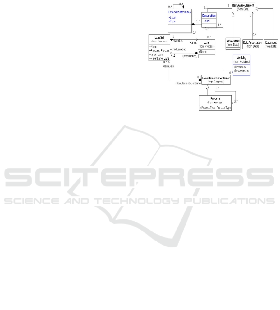
Figure 2: Extract of the used BPMN meta-model.
The two added classes are Description and
ExtendedAttributes. For each BPMN element
(activity, lane, pool, data objects), we associate a
Description that adds a specific information to BPMN
elements in terms of the relationships between them.
For example, in the description of create customer
account activity, we note that a customer can have
one or more accounts. This determines the relation
between the generated classes. The
ExtendedAttributes class specifies the properties of
each BPMN element. For example, the data object
“purchase order” has two extended attributes, which
are the identifier having a pure value and a set of
“order lines” representing a complex attribute
(entity).
5.2 Transformation Rules from BPMN
Model to Class Diagram
DESTINY offers a set of transformation rules from
an annotated BPMN model to generate an aligned
UML class diagram. We note that the rules, that
involve action grammars are based on the
Requirements Specification Language (Smialek and
Nowakowski, 2015). It supposes that:
a. The description field of BPMN element
follows this linguistic pattern: «
BusinessObject + VerbalGroup + [Quantifiers]
+BusinessObject».
b. The BPMN tasks are labeled according to the
following linguistic syntax patterns:
ActionVerb + BusinessObject |
NominalGroup
Designing BP-IS Aligned Models: An MDA-based Transformation Methodology
261
CommunicationVerb + BusinessObject
|NominalGroup + [[to ReceiverName] | [from
SenderName]]
We mean by BusinessObject any entity that
describes the business logic. The NominalGroup is a
set of pre/post-modifiers, which are centered around
a HeadWord that constitutes the BusinessObject. The
pre-modifiers (respectively post-modifiers) can be a
noun, an adjective, or an ed/ing-participle
(respectively, a noun, an adjective, or adverb). The
VerbalGroup indicates the relationship type between
BusinessObjects. The Quantifiers gives an idea of the
multiplicity. We note that the expression between
brackets is optional.
R1. For each description field of BPMN element,
extract the associations and multiplicities
between the generated classes according to the
semantic of VerbalGroup. If it is:
a. “is entirely made of” or “is part of” or any
synonyms, add an aggregation between the
business objects;
b. “is composed of” or any synonyms, add a
composition between the business objects;
c. “Is a/an”, add a generalization/specialization
between the business objects;
d. Else, add an association between the business
objects;
e. For all cases, except the generalization/
specialization, the quantifiers indicates the
multiplicity.
For example, “agent is an employee” is
transformed into a generalization/ specialization
relation between the classes “agent” and “employee”.
R2. For each extended attribute of the BPMN
element, add:
a. An attribute to the class corresponding to the
BPMN element, if its extended attribute is a
noun that merely represents a pure value.
b. Or a new class with the name
extendedAttributeLabel, and an association
between the two generated classes by
applying R1, if the extended attribute is a
complex noun.
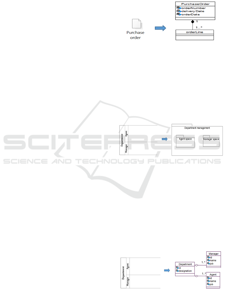
Figure 3 represents the generated class diagram
corresponding to the annotated data object in terms of
extended attributes and description. The description
indicates a relationship between the Purchase order
data object and one of its extended attributes:
orderLine (Each Purchase order is composed of
order lines). The extended attributes of purchase
order data object are orderNumber, deliveryDate,
orderDate, and OrderLine. All of them are
transformed into class attributes, except the
orderLine, which is transformed into a class.
Figure 3: R2 illustration.
R 3: Transform a pool/lane representing a process to
a package and a class.
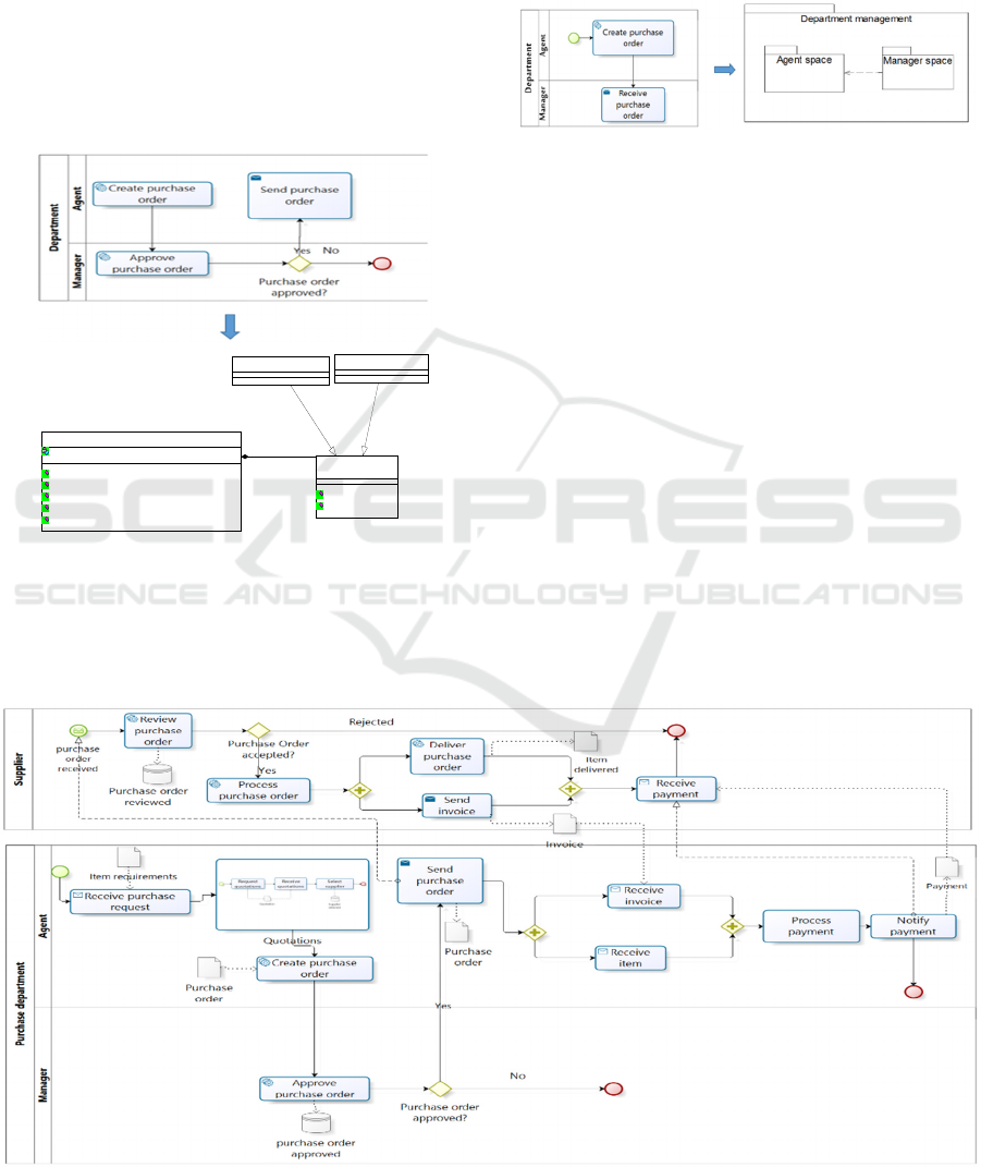
R3.1: The package name depends on the participant
type which is a performer or an entity. If the
participant is a perfomer, then the package name
is a concatenation of the lane name and the word
“space” or “area”. Else, the package name is a
concatenation of the lane name and the word
“management”. For each lane, the package
corresponding to the pool includes the package
corresponding to the lane’s pool (See Figure 4).
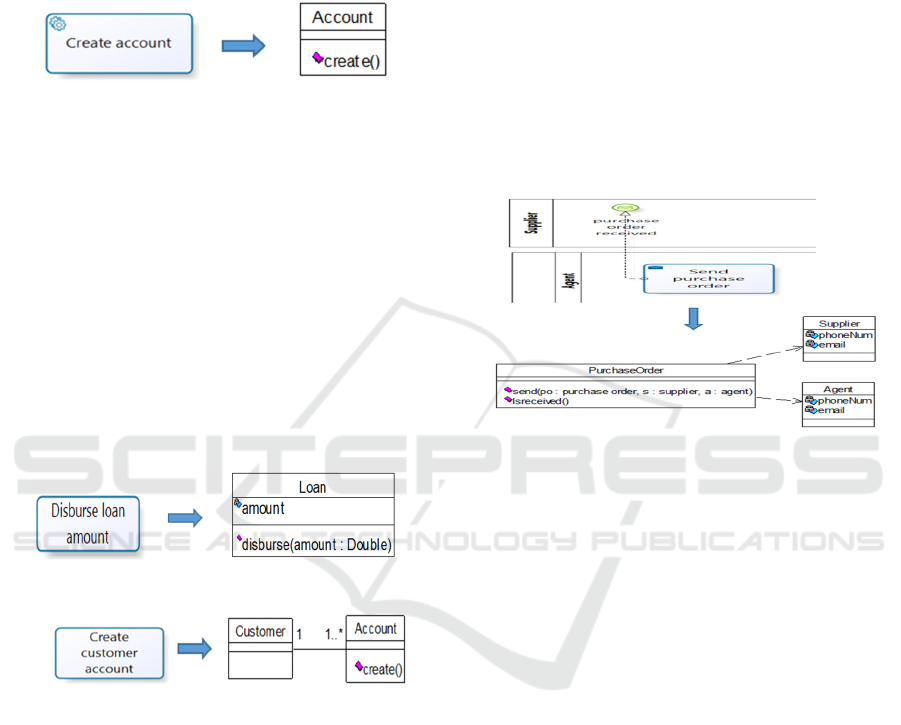
Figure 4: R3.1 illustration.
R3.2: The class name corresponds to the pool/lane
name. The class has as many attributes to the
extended attributes of the corresponding
pool/lane (See R2). The class can have many
associations depending on the pool/lane
description (See R1).
In Figure 5, the description field of Department
pool, defined in its business context, indicates
that the department contains many mangers and
agents. So that, the class diagram shows an
aggregation between the wholeside (Department
class) and the partside (Manager and Agent
classes) as well as a multiplicity 1..n on the
partside.
Figure 5: R3.2 illustration.
ENASE 2018 - 13th International Conference on Evaluation of Novel Approaches to Software Engineering
262
R4. For each service task, we apply R1 and R2. In
addition, if the service task label respects the
renaming pattern:
R4.1: « Action verb + BusinessObject » add 1) a class
with a name BusinessObject, and 2) a new
method with a name ActionVerb() (See Figure 6).
Figure 6: R4.1 illustration.
R4.2: « Action verb + NominalGroup», apply R4.1
on the HeadWord and add:
a. An attribute to the class corresponding to the
HeadWord, if the pre/post-modifier is a noun
that simply represents a pure value. The
attribute has the same name of pre/post-
modifier. The attribute
is also considered as a
parameter of the method ActionVerb() (See
Figure 7);
b. Or a new class with the name pre/post-
modifier, and an association between the two
generated classes (HeadWord and pre/post-
modifier), if the pre/post-modifier is a complex
noun (See Figure 8).
Figure 7: R4.2 illustration.
Figure 8: R4.2 illustration.
We note that adjectives, and ed/ing-participles
premodifiers as well as adjectives, and adverbs post-
modifiers are ignored.
R5. For each script/send/receive task, we apply R1
and R2. In addition, when the task name follows
this pattern:
R5.1: «CommunicationVerb+ BusinessObject +
[[to ReceiverName] | [from SenderName]] », add
(See Figure 9):
a. new Classes with name BusinessObject,
senderName and ReceiverName, if they aren’t
already created;
b. new attribute email or phoneNumber in the
Class with a name SenderName and
ReceiverName;
c. Method with a name CommunicationVerb() to
the class corresponding to the business object.
o In the case of Send Task, add three
parameters to CommunicationVerb()
method: “bo” instance of
BusinessObject and “r” instance of class
which receives “bo” and “s” instance of
class which sends “bo”.
o In the case of receive Task, substitute
the CommunicationVerb() method with
a boolean method “isReceived()”.
o In both cases, add a dependency
between the BusinessObject class and
Sender and Receiver classes, when there
is not an association between them.
Figure 9: R5.1 illustration.
R5.2: « CommunicationVerb+ NominalGroup + [[to
ReceiverName] | [from SenderName]]», apply
R5.1 on the HeadWord and add:
a. An attribute to the class corresponding to the
HeadWord, if the pre/post-modifier is a noun
that simply represents a pure value. The
attribute has the same name of pre/post-
modifier.
b. or a new class with the name pre/post-
modifier, and an association between the
two generated classes (HeadWord and
pre/post-modifier), if the pre/post-modifier
is a complex noun.
We note when this expression [[to ReceiverName]
| [from SenderName] ] is omitted, then we can extract
this semantic information from the description field
of the activity element according to R1.
R6. Transform to a class each data store/object,
identified by a name, if it is not already
generated. The class name has the same data
object name. Then, R6 calls R1 and R2.
The following rule structures the class diagram by
using the State design pattern (Gamma et al., 1995).
This design pattern is composed of three classes: a
Context class, a State abstract base class, and
different State concrete classes. The Context class
Designing BP-IS Aligned Models: An MDA-based Transformation Methodology
263
has a private attribute called “state” and its getter and
setter methods. It is related to the Abstract class by a
composition relation.
R7. If the gateway label refers to an existing business
object or a new one, then apply the State design
pattern on it with: the Context class name
corresponds to the business object name; the
State Abstract class name is a concatenation of
the “Business object” name and “State” Word;
and the super class has as many sub classes as the
number of outgoing gateway alternatives (See
Figure 10).
Figure 10: R7 illustration.
R8. If the pool/lane sends or receives respectively a
message/sequence flow to/from another one,
then transform the message/sequence flow into a
dependency relation between the associated
packages/sub packages containing the
corresponding classes of these tasks (Figure 11).
We note that this rule is applicable only if there is
no mutual dependency between the pools/lanes. A
mutual dependency is expressed by a pool/lane that
sends and receives message/sequence flows.
Figure 11: R8 illustration.
6 CASE STUDY
To illustrate the application of our transformation
rules, we use the “Purchase department process”
model (see Figure 12) which is an official BPMN
example (ISO/IEC 19510, 2013).
Figure 13 shows the class diagram mode which
was generated as follows: First, by applying R3.1, the
Purchase Department pool and each of its lanes
(Agent, Manager) as well as the Supplier pool are
transformed respectively to packages named
“Purchase department management”, “Agent
space”, “Manger space”, and “Supplier Space”.
Second, we generate four classes by applying R3.2,
which are “Purchase Department”, “Agent”,
“Manager”, and “Supplier”. Since R3.2 uses R1,
we create an aggregation with multiplicity
between the “Purchase Department” and “Agent”
Figure 12: Purchase order Business Process in BPMN (ISO/IEC 19510, 2013).
PurchaseOrder
state : PurchaseOrderState
send(po : purchase order, s : supplier, e : employee)
create()
approvalRequest()
getPurchaseOrderState()
setPurchaseOrderState()
RejectedPurchaseOrder
ApprovedPurchaseOrder
PurchaseOrderState
approve()
reject()
<<Interface>>
1..*1..*
ENASE 2018 - 13th International Conference on Evaluation of Novel Approaches to Software Engineering
264
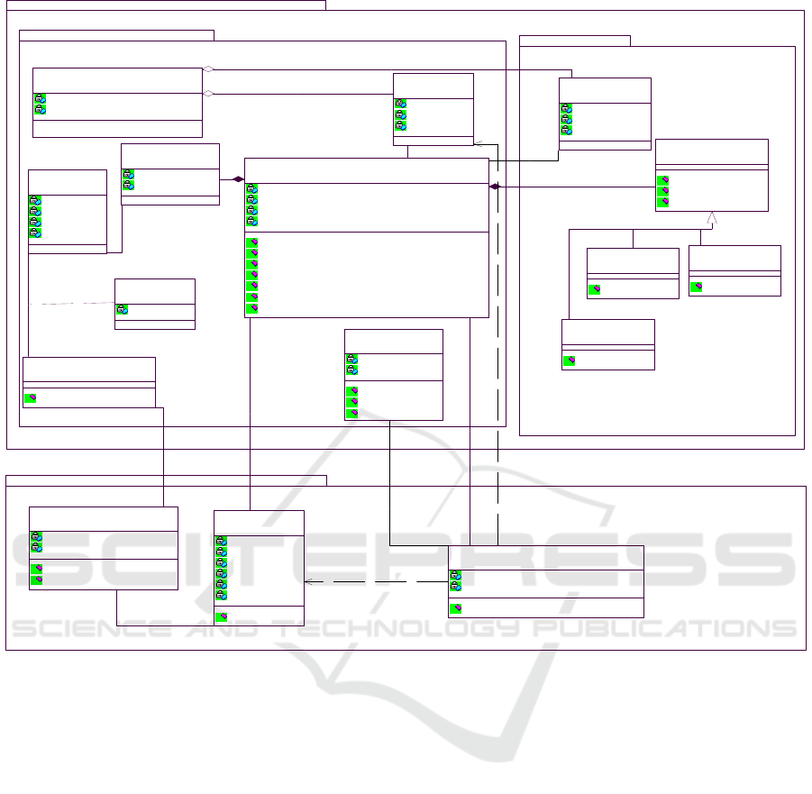
Figure 13: The generated class model for the purchase order business process model.
(respectively, “Manager”) classes. The rule R3.2
calls R2, which adds the attributes to all classes
based on the business context of the corresponding
pool and lanes.
Third, we apply R4.1 on the following service
tasks: “Create purchase order”, “Approve
purchase order”, “Deliver purchase order”,
“Review purchase order”, “Process purchase
order”, “Process payment”, “Notify payment”,
“Request quotations”, and “Select supplier”. This
rule generates three classes: “Purchase order”,
“Payment”, and “Quotation”. The “Supplier”
class is already generated by R3.1. It adds the
methods:
− create(), approve(), deliver(), review() and
process() to “Purchase order” class;
− process() and notify() to “Payment” class;
− request() to “Quotation” class;
− select() to “Supplier” class.
Afterward, by applying R5.1, the task “send
purchase order” (respectively “send invoice”)
generates a method “send()” with three
parameters : “po” instance of the business object
purchase order , “s” instance of supplier who
receives “po” and “a” instance of an agent class
who sends the purchase order (respectively,
generates a method “send()”
with three
parameters : “in” instance of the business object
invoice, “a” instance of agent who receives “in”
and “s” instance of an agent class who sends the
invoice). In addition, we apply R5.1 on receive
tasks which are “Receive invoice” “Receive
purchase request”, “Receive payment”, “Receive
item”, and “Receive quotation”. According to this
rule, a Boolean method “isReceived” is added to the
generated classes: “Invoice”, “Purchase request”,
“Item”, “Payment”, and “Quotation”.
By applying R6, the transformation of all data
objects do not add new classes. However, R6
Purchase Department Management
Agent Space
(from Purchase Department Management)
Manager Space
(from Purchase Department Management)
Supplier Space
Approved
approve()
(from Manager Space)
Accepted
accept()
(from Manager Space)
Rejected
reject()
(from Manager Space)
Request Line
qty
(from Agent Space)
Purchase Order Request
isReceived() : Boolean
(from Agent Space)
quotation
quotationDiscountAmount
numberQuotationRequested
request()
isReceived() : Boolean
(from Supplier Space)
0..*
1
0..*
1
Ite m
id
designation
unit-price
stock_Qty
(from Agent Sp
a
...)
0..*
1..*
0..*
+requested
1..*
Purchase Department
id
designation
(from Purchase Department Managem
e
...)
Agent
id
name
job
(from Agent Space)
1..*1..*
Purchase Order State
approve()
reject()
accept()
(from Manager)
Supplier
id
name
country
phone_number
email
adress
select()
(from Supplier Space)
1..*
1
1..*
1
Order Line
orderLineNumber
quantity
(from Agent Space)
1
1..*
1
1..*
Manager
id
name
job
(from Manager Space)
1..*1..*
Purchase Order
state : Purchase Order State
orderNumber
deliveryDate
orderDate
create()
send(po : Purchase Order, a : Agent, s : Suppli
e
...
approve()
getPurchaseOrderState()
setPurchaseOrderState()
deliver()
isReceived() : Boolean
(from Agent Space)
1..*
1
1..*
1
0..*0..*
1
1..*
1
1..*
1..*1..*
1..*
1
1..*
1
Invo ic e
invId
invDate
send(i : Invoice, s : Supplier, a : Agent)
(from Supplier Space)
1
1
1
1
Payment
option
term
process()
notify()
isReceived()
(from Agent Space)
1
1
1
1
Designing BP-IS Aligned Models: An MDA-based Transformation Methodology
265

enhances the existing classes by calling R1 and R2,
which add attributes, classes and associations. For
example, we have added the attributes deliveryDate,
orderDate, orderNumber to “Purchase order”
class because these extended attributes are pure
values. Furthermore, the extended attribute
“orderLine” is a complex entity. According to R2,
we extract a new class “orderLine”, and a
composition relation between the latter and
“Purchase order”.
By applying R7 on two gateways “purchase order
approved” and “purchase order accepted”, we
create an abstract class “Purchase order state” and
three concrete classes “Approved”, “Accepted”,
and “Rejected” that correspond to outgoing
gateway alternatives. Finally, we add a composition
between the “Purchase order state” and “Purchase
order” classes.
7 CONCLUSIONS
This paper proposed a transformation-based
approach to generate class diagrams from business
process models. It provides for the generation of IS
entities and their relations that are aligned to the
business logic. Compared to existing works, our
approach has the merit of accounting for both the
semantic and structural aspects of the business
process model. To do so, we proposed to define the
business process context expressing the relation
semantics and type.
Ongoing work focuses on 1) conducting an
experimental evaluation to assess the coverage and
precision of all generated class diagrams; and 2)
enhancing the transformations in order to cover
interaction, and component diagrams.
REFERENCES
Archimate 2.1 Specification, 2013. http://www.theopen
groupbookshop.com/9789401800037. Van Haren
Publishing, December.
Aversano, L., Grasso., C., Tortorella, M., 2016. Managing
the alignment between business processes and
software systems. In journal information and software
technology, Volume 72 Issue C, April, pp. 171-188.
Cruz, E. F. Machado, R. J., Santos, M. Y., 2012. From
business process modeling to data model: A
systematic approach. In QUATIC’12, 8th
International Conference on the Quality of
Information and Communications Technology.
Lisbon, Portugal, 2-6, September, pp.205-210.
De la Vara, J.L, Fortuna, M.H, Sanchez Diaz, J., Lima
Werner, C.M, Borges, M.R.S, 2009. A requirements
engineering approach for data modelling of process-
aware information systems. In BIIS’09, Business
Information Systems. vol. 21 of LNBIP, Springer, pp.
133–144.
Gamma et al. (1995): Gamma, E., Helm, R., Johnson, R.,
Vlissides, J., 1995. Design Patterns – Elements of
Reusable Object-Oriented Software. Verlag:
Addison-Wesley Longman; Adresse: Amsterdam,
416 pages.
ISO/IEC 19510. 2013. Information technology -- Object
Management Group Business Process Model and
Notation.
Jammal, M., Ben Ayed, M., Ben-Abdallah, H., 2017.
DESTINY: a moDel-driven procESs-aware
requiremenTs engineerINg methodo-logY. In
ICSOFT’17,10
th
Inter Conf on Software Technologies
and Applications, Spain, July, pp. 79-86.
Meyer, A., Pufahl, L., Fahland, D., Weske, M., 2013.
Modeling and Enacting Complex Data Dependencies
in Business Processes. In BPM’13, 11
th
proceedings
of Inter Conference, vol. 8094, China, August Lecture
Notes in Computer Science 8094, pp. 171-186.
OMG, 2006. The Fast Guide to Model Driven
Architecture, [Online] [Accessed 2017].
OMG-MOF, 2015. OMG Meta Object Facility (MOF)
Core Specification. [Online] [Accessed 2017]
OMG-UML, 2015. OMG Unified Modeling Language
(OMG UML). formal/2015-03-01. [Online].
Przybyłek, A., 2014. A Business-Oriented Approach to
Requirements Elicitation. In Proceedings of the 9th
International Conference on Evaluation of Novel
Approaches to Software Engineering (ENASE 2104),
Lisbon, Portugal, 28-30 April.
Rhazali, Y. Hadi, Y. Mouloudi, A., 2016. A Based-Rule
Method to Transform CIM to PIM into MDA. In
International Journal of Cloud Applications and
Computing, IJCAC 6(2).pp.11-24.
Rostami, K., Heinrich, R., Busch, A., Reussner, R. H,
2017. Architecture-Based Change Impact Analysis in
Information Systems and Business Processes. In
ICSA’17, IEEE International Conference on Software
Architecture. Gothenburg, Sweden, April 3-7,
pp.179-188.
Smialek, M., Nowakowski, W., 2015. From
Requirements to Java in a Snap - Model-Driven
Requirements Engineering in Practice. Springer 2015,
ISBN 978-3-319-12837-5, pp. 1-296.
ENASE 2018 - 13th International Conference on Evaluation of Novel Approaches to Software Engineering
266
