
Detecting and Describing Variability-Aware Design Patterns in
Feature-Oriented Software Product Lines
Sven Schuster, Christoph Seidl and Ina Schaefer
TU Braunschweig, Braunschweig, Germany
Keywords:
Software Product Line, Feature-Oriented Programming, Design Pattern, Family Role Model.
Abstract:
Software Product Lines (SPLs) enable customization by reusing commonalities and variabilities within a fa-
mily of similar software systems. Design patterns are best practices of established solutions in object-oriented
source code for recurring design challenges. Although certain design patterns realize variability, they are only
defined in the context of stand-alone systems and not for SPLs. Employing design patterns to realize variabi-
lity allows using best practices in design for SPL development. However, the exact usage of design patterns
within SPLs has not been explored, and a formal notation to capture their usage within different features does
not exist. In this work, we provide a model-based analysis method to determine the variability-aware usage
of design patterns in source code within the context of Feature-Oriented Programming (FOP). Moreover, we
introduce Family Role Models (FRMs) as an extension to role modeling, which offer a language-independent,
unified, formal notation for decomposed design patterns. We apply the analysis method in a case study on the
variability-aware usage of design patterns in feature-oriented SPLs and derive FRMs from the results.
1 INTRODUCTION
In recent years, Software Product Lines (SPLs) gai-
ned momentum due to an increasing demand for cu-
stomizing software (Clements and Northrop, 2001;
Pohl et al., 2005). SPLs reuse commonalities and va-
riabilities to realize customization while decreasing
cost and effort. Feature models (Kang et al., 1990;
Czarnecki and Eisenecker, 2000) are variability re-
presentations for SPLs describing commonalities and
variabilities on a conceptual level in terms of fea-
tures (e.g., see Figure 10). Features may be either
optional or mandatory and are usually arranged in a
tree-structure (Kang et al., 1990). Feature-Oriented
Programming (FOP) (Prehofer, 1997; Batory et al.,
2004) is a compositional approach for SPL develop-
ment, which allows modularizing realization artifacts,
such as source code in various languages, along in-
crements to functionality of individual features (Apel
and Kästner, 2009). According to a configuration for
a stakeholder (i.e., a specific feature selection), a core
module is composed with feature modules of the se-
lected features to form a particular variant of the SPL.
Software design is a crucial task during software
development. Various design concepts emerged, in-
cluding design patterns as best practices for recur-
ring design problems in Object-Oriented Program-
ming (OOP) (Gamma et al., 1994) in various langua-
ges. To guide the design process, catalogs of design
patterns have been assembled that list patterns by the
main concern they address. Some of these patterns
address encapsulating variation to achieve modularity
and reusability (Apel et al., 2013).
Due to its modular nature, FOP offers a new layer
of design that allows refining realization artifacts and,
thus, extending them with new functionality. Howe-
ver, only little is known about realizing high-quality
design in the context of FOP (Apel and Beyer, 2011;
Kästner et al., 2011). Regarding design patterns,
it is known that they are applied in the context of
FOP (Schuster et al., 2013), but it is unclear exactly
how they are used to implement variability. Moreover,
no dedicated formalism for the description of design
patterns in the context of SPLs exists.
In this work, we analyze the usage of design pat-
terns in the context of source code used within FOP,
i.e., how their realization is decomposed along featu-
res. As design patterns are established solutions for
common design problems, we cannot reason on their
variability-aware implementation, but have to collect
evidence on their existence and their exact applica-
tion. This information is intended to serve as ba-
sis for documenting best practices in designing SPLs,
which may be used for the implementation of vari-
Schuster, S., Seidl, C. and Schaefer, I.
Detecting and Describing Variability-Aware Design Patterns in Feature-Oriented Software Product Lines.
DOI: 10.5220/0006749307310742
In Proceedings of the 6th International Conference on Model-Driven Engineering and Software Development (MODELSWARD 2018), pages 731-742
ISBN: 978-989-758-283-7
Copyright © 2018 by SCITEPRESS – Science and Technology Publications, Lda. All rights reserved
731
Component {abstract}
+ operation()
+ add(Component)
+ remove(Component)
Client
Leaf
+ operation()
Composite
+ operation()
+ add(Component)
+ remove(Component)
(a) Class diagram of the Composite pattern
Client
Component
Leaf
Composite
0..∗
(b) Role diagram of the
Composite pattern adap-
ted from (Riehle and
Gross, 1998).
Subject
Observer
0..∗
(c) Role diagram of the
Observer pattern.
Resource {abstract}
Program
File Folder
Component
Leaf
Composite
Client
Subject
Observer
(d) Class ability diagram mapping Composite
and Observer patterns to a tree-structured file
system.
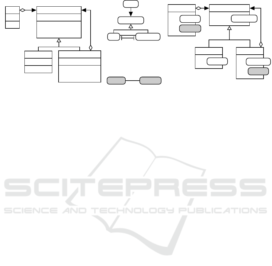
Figure 1: Specifying and applying the Composite and Observer patterns using role modeling.
ability within various object-oriented (OO) langua-
ges. To obtain the relevant information, we present
a model-based analysis method and a corresponding
implementation based on the Eclipse Modeling Fra-
mework (EMF) and the Java Model Parser and Prin-
ter (JaMoPP) to allow an automated analysis of the
design pattern usage in feature-oriented SPLs. In this
work, we focus on design patterns identified as bene-
ficial to implementing variability due to their struc-
tural properties and intended use–namely the Com-
posite, Observer, Strategy and Template Method pat-
terns (Apel et al., 2013).
The contribution of this paper is twofold:
1. We provide a model-based analysis method to
allow the automated detection of design pattern
usage in FOP.
2. We introduce Family Role Models (FRMs) as a
domain-specific language (DSL) based on role
modeling (Reenskaug et al., 1996) to describe
the variability-aware usage of design patterns in
SPLs independent of the concrete implementation
in source code.
We evaluate our approach by analyzing seven ex-
isting SPLs for variability-aware usage of selected de-
sign patterns and we document our findings to serve
as basis for future implementations.
The rest of the paper is organized as follows. In
Section 2, we provide background information on
design patterns and role modeling. In Section 3,
we present the model-based analysis method. In
Section 4, we introduce FRMs as a DSL for descri-
bing variability-aware design patterns. In Section 5,
we describe our case study on the decomposition of
variability-aware design patterns. In Section 6, we
discuss related work. In Section 7, we close with a
conclusion and present an outlook to future work.
2 BACKGROUND
In the following, we describe design patterns as best
practices for design in object-oriented languages and
role modeling as a notation to capture dynamic object
collaborations instead of static class design.
2.1 Design Patterns
Design patterns are time-proven standard solutions
for common, recurring design problems in object-
oriented software. (Gamma et al., 1994) documented
design patterns by extracting best practices from real-
world examples and describing them consistently.
Despite design patterns being general descriptions
of best practices, they are documented using a nota-
tion similar to class diagrams, which would suggest a
definite design that can be copied to be used. Howe-
ver, design patterns do not constitute final design de-
cisions, but rather general descriptions of how to solve
the problem, i.e., design patterns are not static soluti-
ons. To apply a design pattern in an OO-language, it
has to be tailored to the specific application, e.g., class
and operation names may have to be adapted.
Figure 1a illustrates the Composite pat-
tern (Gamma et al., 1994) as an example of a
design pattern. The intent of the Composite pattern
is to realize a hierarchical tree structure to represent
part-whole hierarchies of components. The Com-
posite pattern consists of a Client, referencing
a Component. Instances of the Component
can either be of type Leaf or Composite.
Composites hold children by referencing the
common superclass Component, i.e., children can
be treated uniformly, regardless whether they are
instances of Leaf or Composite.
MOMA3N 2018 - Special Session on Model Management And Analytics
732
A
B
(a)
A
B
0..∗
(b)
A
B
(c)
A
B
(d)
A
B
(e)
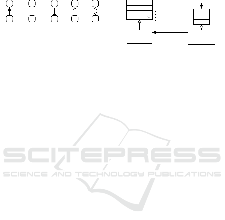
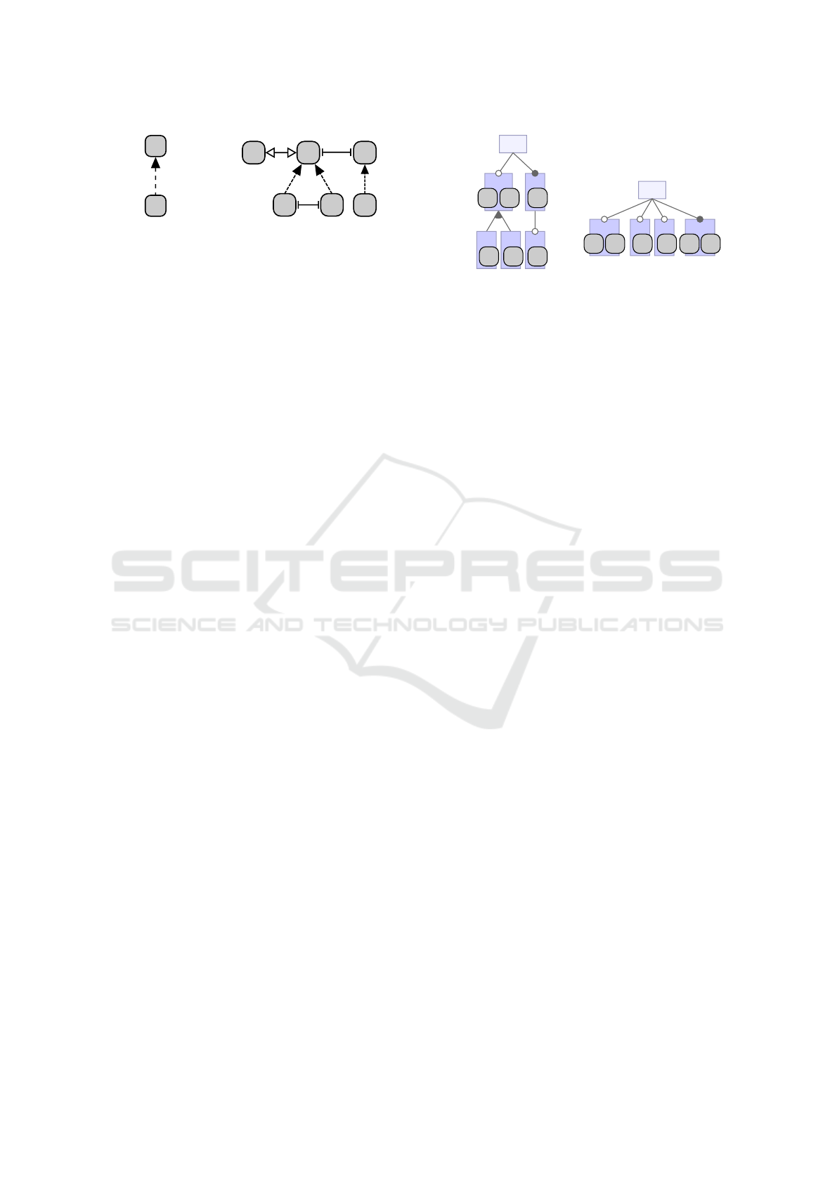
Figure 2: Role diagram notation (Riehle and Gross, 1998).
(a) Use (b) Association (c) Prohibition (d) Implication (e)
Equivalence.
2.2 Role Modeling
In OOP, developers are concerned with static class de-
sign, i.e., object composition via references as well
as class inheritance (as captured in UML class di-
agrams). However, depending on the view on the
object and the considered interactions, an object can
play multiple different roles in a specific context. To
capture dynamic object collaborations, role modeling
was introduced (Reenskaug et al., 1996).
Role modeling is a modeling language addressing
the collaborations of different “players”. In a role
model, roles as well as constraints between these ro-
les are used to describe such collaborations (Riehle
and Gross, 1998). Roles may be mapped to rigid ob-
jects (e.g. objects of OOP languages, model elements,
etc.), which is perceived as the object playing that
role. However, role modeling is a general modeling
notation not limited to OOP, which means that roles
can be mapped to any kind of entity of other modeling
concepts, such as, e.g., features of a feature model.
As the intent of role modeling is to model col-
laborations instead of a definite design, it is a suita-
ble basis for describing design patterns (Riehle, 1996;
Riehle, 1997). In this work, we adopt the role diagram
language introduced by (Riehle and Gross, 1998),
consisting of five role constraints (cf. Figure 2).
Use. An object playing role B uses an object playing
role A.
Association. An object playing role B “knows” of a
given number of objects playing role A.
Prohibition. An object playing role B may never
play role A in the same context.
Implication. An object playing role B also plays
role A.
Equivalence. An object playing role B also plays
role A and vice versa.
Figure 1b depicts a role model for the Compo-
site pattern (Riehle and Gross, 1998). To realize the
unified treatment of Leaf and Composite, objects
playing the Leaf or Composite role are also regar-
ded Components. An object playing the Composite
role references a number of objects playing the Leaf
role, which creates the parent-child relation. Objects
Subject
+ attach(Observer)
+ notify()
ConcreteSubject ConcreteObserver
+ update()
Observer
+ update()
for all o in observers {
o.update()
}
subject
observers
0..∗
Figure 3: Class diagram of Observer pattern (adapted from
Gamma et al. (Gamma et al., 1994, p. 294)).
playing the Composite role may not play the Leaf role
in the same context, i.e., an object may not reference
itself as a child. This way, a part-whole hierarchy may
be constructed.
Furthermore, Figure 1c depicts a role model for
the Observer pattern (Riehle and Gross, 1998). The
Observer pattern is used to achieve an event notifica-
tion of objects (Observers) depending on another ob-
ject’s (Subject) state. Hence, a Subject is observed by
a number of Observers.
These language and realization-independent re-
presentations of design patterns may be mapped to a
static class design such as the tree-structured file sy-
stem illustrated in Figure 1d. This way, a Folder
may contain an arbitrary number of Resources,
which can either be instances of File or Folder.
Moreover, the Program may access a Resource
and observe a Folder, e.g., for file changes.
Although this is a suitable implementation for the
Composite and Observer patterns, it is not the only
possible implementation. Different incarnations of
the patterns can be implemented by creating alterna-
tive mappings to classes that fulfill the role models
of the patterns. Hence, role modeling is a suitable
technique to describe the general collaborations of a
design pattern independently of its actual implemen-
tation and the respective concrete language.
3 DETECTING
VARIABILITY-AWARE DESIGN
PATTERNS
In previous work (Schuster et al., 2013), we establis-
hed that design patterns exist in feature-oriented SPLs
and that they are implemented across several features.
However, there was no inspection of the actual usage
of these patterns, i.e., how exactly they are decompo-
sed over features. In this section, we present an analy-
sis method to automatically identify and locate design
pattern instances and determine how a detected design
pattern instance is distributed across features.
Detecting and Describing Variability-Aware Design Patterns in Feature-Oriented Software Product Lines
733
FopCompilationUnit - [BFS] GPL.Vertex.java
Class Vertex
Expression Statement
Expression Statement
FopIdentifierReference
FopMethodCall
Field [BFS] GPL.Vertex.visited
Field [DFS] GPL.Vertex.visited
Class Method [BFS] GPL.Vertex.display
Class Method [Cycle] GPL.Vertex.display
...
Field visited
Class Method display
FopClassifierReference (implements)
ReturnType: Void
Condition
Interface [Base] GPL.NeighborIfc
Interface [WeightedWithEdges] GPL.EdgeIfc
Interface [Base] GPL.EdgeIfc
(a)
(b)
(c)
(c)
Figure 4: Extract of a 150% ASG for feature-oriented Java
code from GPL.
3.1 Model-Based Representation of
Feature-Oriented Code
The analysis method should capture the entire varia-
bility and, thus, each occurrence of a design pattern
with each possible decomposition. To this end, the
analysis has to be performed family-based, i.e., con-
sidering all features. Hence, the system representa-
tion must capture the entire product line, in contrast to
capturing a single product. We decided to develop a
new system representation for feature-oriented code,
which can express the features as enclosed units in the
Abstract Syntax Tree (AST) to express variability. In
reference to the notion of a 150% model with annota-
tive variability realization mechanisms, we call this a
150% AST (Schaefer et al., 2012).
We retrieve the 150% AST by parsing the source
code of all available feature-modules of FOP and for-
ming an AST that contains the respective variabili-
ties for the software family instead of the information
for just one system. We realized the 150% AST for
feature-oriented SPLs developed in Java by extending
JAMOPP
1
, the Java Model Parser and Printer. JA-
MOPP is a parser for Java source code that represents
parsed code as an EMF
2
-based model. To obtain the
150% AST, extensions to JAMOPP are necessary be-
cause feature modules encompass illegal Java code.
1
http://www.jamopp.org
2
http://www.eclipse.org/modeling
<<extends>>
<<extends>>
<<extends>>
<<extends>>
SubjectNotifySubjectAdd SubjectField
0..
*
Observer
ConcreteSubject ConcreteObserver
notify
attach
updatenotify
Figure 5: Decomposed role diagram of Observer pattern.
They contain the original-call, which is used to
realize method refinements in the FOP tool FEATU-
REHOUSE (Apel et al., 2009). Moreover, reference
resolving has to be expanded as feature modules con-
tain inter-feature references (i.e., references to classi-
fiers, methods and identifiers located within other fe-
atures). To facilitate family-based analysis, the 150%
AST should represent references to elements as multi-
target references (i.e., references to classifiers, met-
hods and fields can target multiple declarations). Exe-
cuting reference resolving creates an Abstract Syn-
tax Graph (ASG) from the 150% AST, which we ac-
cordingly call 150% ASG. The created 150% ASG
captures multiple declarations and refinements of ele-
ments when resolving a reference. Furthermore, each
class in a feature module should be annotated with its
containing feature to capture the variability informa-
tion. We extended JAMOPP’s metamodel, parser and
reference resolver accordingly.
Figure 4 illustrates an extract of a 150% ASG from
GPL. The differences to a Java ASG are annotated:
(a) A FopCompilationUnit encompasses a
class within a feature module annotated with the
containing feature.
(b) References to classifiers are, e.g., contained in the
implements relation of classes. While this relation
may capture multiple interfaces, it may now target
multiple declarations of one interface.
(c) Elements (i.e., identifier and methods) may be de-
clared multiple times or refined in different fea-
tures. Hence, references to such elements target
multiple declarations in the 150% ASG.
In a nutshell, the devised 150% ASG contains
variability information on each class in each feature
module, a resolved original-call as well as resolved
multi-target references, whose targets may be located
in different features.
3.2 Representation of Design Patterns
To automatically detect pattern instances, a represen-
tation for design patterns has to be devised that is fine-
grained enough to identify technical realizations of a
MOMA3N 2018 - Special Session on Model Management And Analytics
734
Matches
Structural
Conditions
150% AST
Post-
processing
Identified
Decomposed
Design Patterns
Derive
Structural
Conditions
Feature-
Oriented
Parser
Design Pattern
Role Model
FOP Code
Detect
Matches
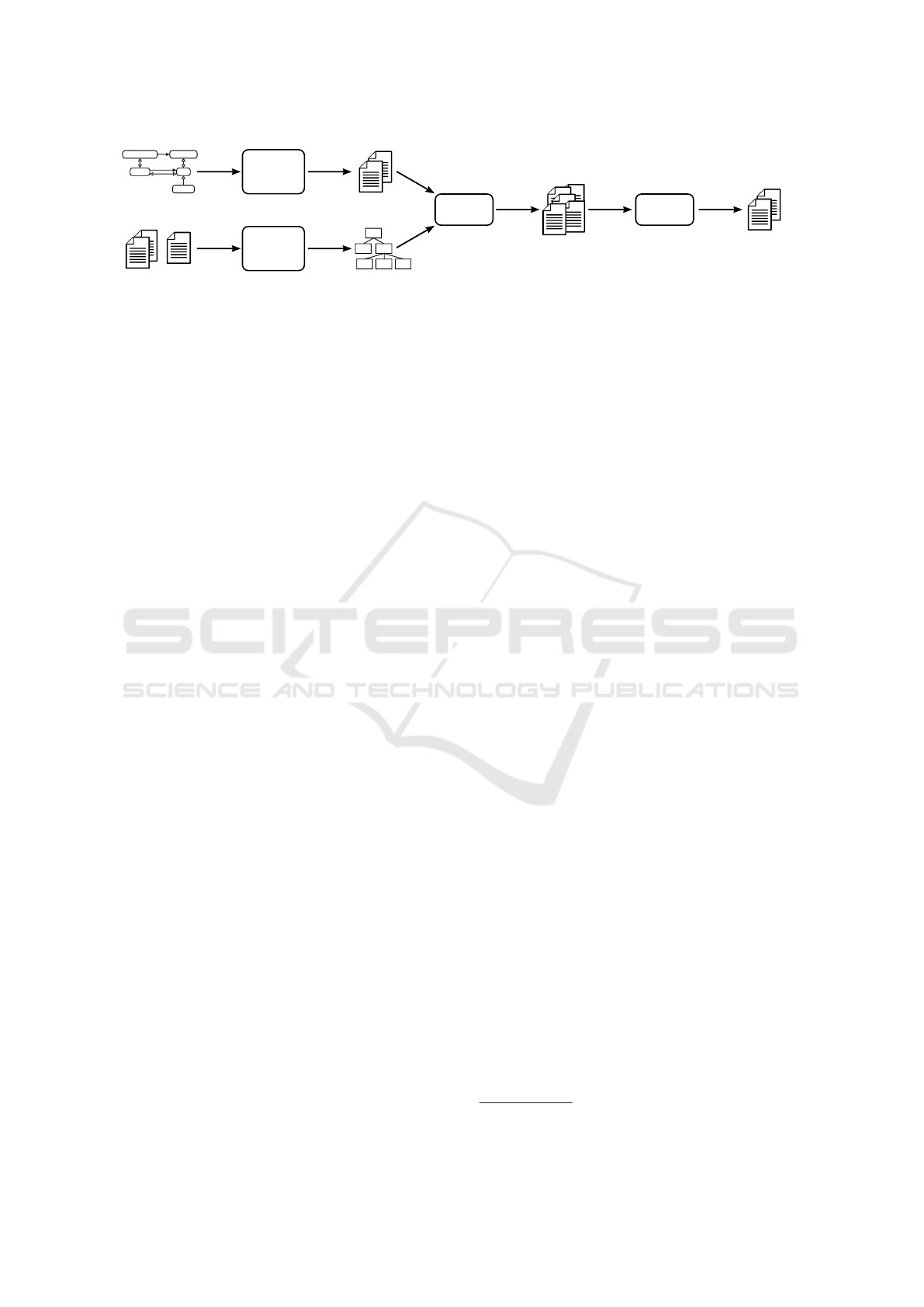
Figure 6: Workflow of the family-based design pattern detection technique.
pattern. (Seidl et al., 2017) introduced a notation ba-
sed on role modeling to describe the characteristics
of design patterns. As it is used to detect decom-
posed design patterns across features, the maximum
possible decomposition of the necessary elements that
form a design pattern has to be described. The de-
tection technique uses this notation as input to analyze
which elements are applied in a decomposed manner.
In Section 2.2, we described the benefits of using
role models to describe design patterns. Using multi-
ple roles, we can further describe the decomposition
of a pattern role along multiple features. The equi-
valence relation between roles denotes that these ro-
les contribute to the same realization artifact. We il-
lustrate the description of decomposed patterns using
the Observer pattern as an example. Figure 3 shows
the class diagram of the essential elements required
to form the Observer pattern (Gamma et al., 1994,
p. 294). The names are merely used as identifiers for
the different elements.
Figure 5 depicts a design pattern role model
(DPRM), which describes the maximum decomposi-
tion of the elements necessary to form the Observer
pattern of Figure 1c. The maximum decomposition of
a pattern is derived by reasoning which elements can
be introduced in different features. For the Subject,
e.g., an attach method, a notify method and an
association to the Observer are necessary. Those
elements manifest in adding methods and fields to the
class. In the role diagram in Figure 5, this manifests
in the Subject being split into the three roles Subject-
Add for the attach method, SubjectNotify for the
notify method and SubjectField for the association
to the Observer. As these three roles contribute
to the same Subject class, they are connected by
an equivalence constraint. In contrast, the associa-
ted Observer must not contribute to the same realiza-
tion artifact as specified by the prohibition. Finally,
concrete implementations of the Subject and Obser-
ver are required, which inherit from (or are the same
as) the types playing the Subject or Observer roles.
In OOP, a role is mapped to an object playing that
role. In FOP, roles of a decomposed role model are
mapped to class contributions. While in FOP, the de-
finition of a class contribution within a feature is re-
ferred to as a role (Smaragdakis and Batory, 2002),
to avoid terminology conflicts with the role modeling
paradigm, we call this a feature-oriented role.
3.3 Design Pattern Detection
Detecting design patterns is an extensive research to-
pic for OO-languages (Rasool and Streitferdt, 2011).
However, none of the existing approaches is tailored
to SPLs. We devised a family-based approach, which
can be applied to a 150% ASG.
The detection technique is based on that of (Heu-
zeroth et al., 2003) who developed algorithms to de-
tect the specific structural characteristics of design
patterns. In addition, our approach is influenced by
the detection technique of (Tsantalis et al., 2006) who
use graph pattern matching to identify graph structu-
res that are similar to design patterns.
Figure 6 illustrates the workflow of our detection
technique. From the DPRM, we manually derive
structural conditions that have to be met in order for a
specific class and object collaboration to form parts of
a design pattern. These conditions include, e.g., that
a feature-oriented role has to contain a specific met-
hod or that two feature-oriented roles contribute to the
same class. We detect structural matches for a design
pattern through graph matching of the structural con-
ditions on the 150% ASG.
We implemented the structural design pattern de-
tection with EMF-INCQUERY
3
, a tool for high-
performance graph searches on EMF models. EMF-
INCQUERY offers a declarative query language,
which we used to encode the derived structural con-
ditions. The query language supports defining impre-
cise queries, e.g, transitive relations. This is helpful
for detecting variants of design patterns. Based on the
query a matcher is generated that searches an EMF
model for the specified graph structures. This matcher
can be run on the 150% ASG of an SPL resulting in
a set of candidates for design pattern instances. We
further use automatic postprocessing steps (e.g., data
and control flow analyses) to eliminate false positives
and duplicates from structural matches.
3
http://www.eclipse.org/incquery
Detecting and Describing Variability-Aware Design Patterns in Feature-Oriented Software Product Lines
735
A
B
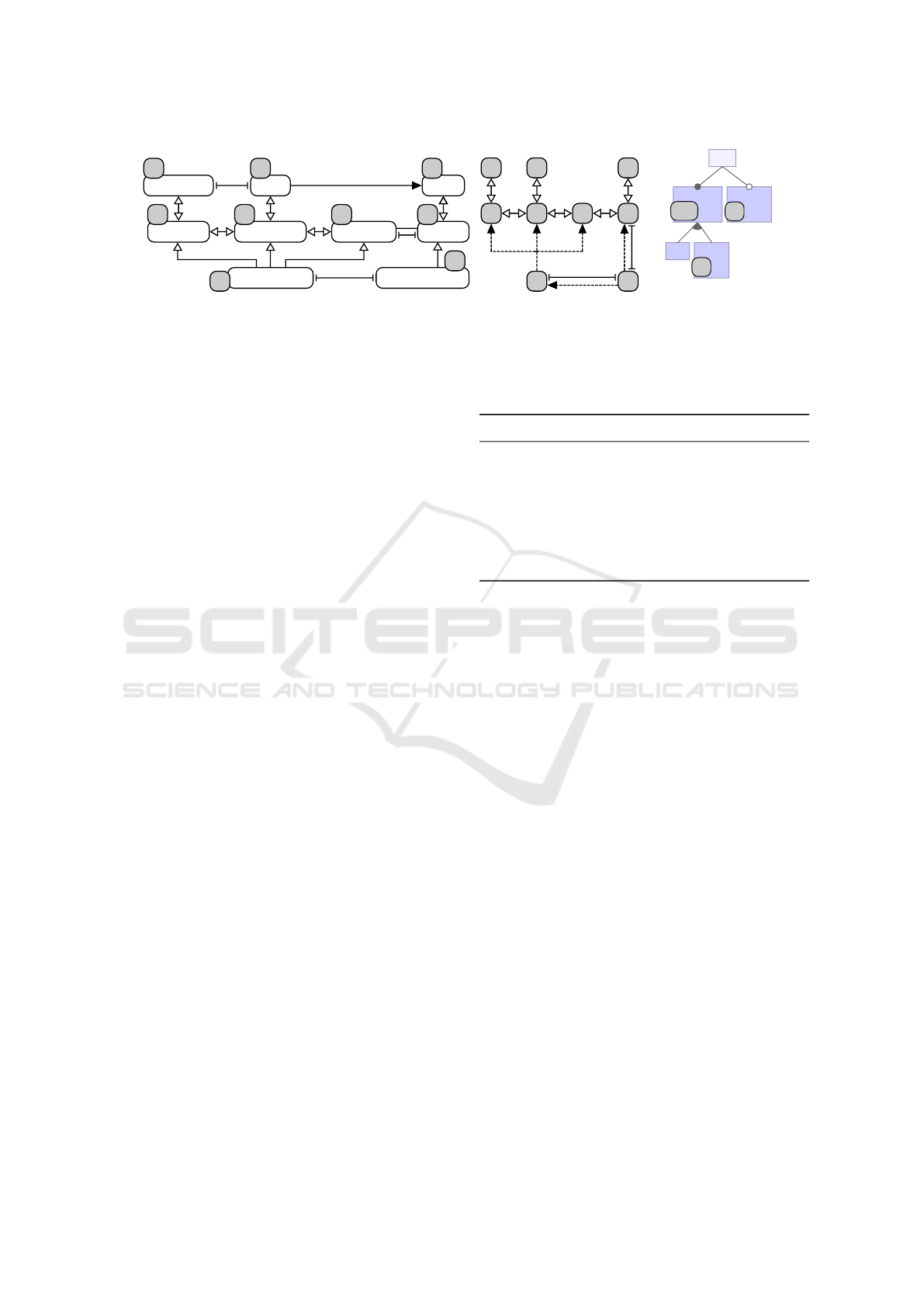
(a) Requires relation.
A
B
D
E
C
F
(b) Example of Family Role Model.
Figure 7: Language extension of role modeling and exam-
ple for Family Role Models (FRMs).
4 DESCRIBING
VARIABILITY-AWARE DESIGN
PATTERNS
In previous work, a modeling notation to describe de-
sign patterns in SPLs, which is based on role models
and which is called Family Role Model (FRM) was
introduced (Schuster, 2014; Seidl et al., 2017).
Feature models describe a definite design of vari-
ability, while different feature models can express the
same variability in multiple ways, i.e., different se-
mantically equivalent feature models can exist (Alves
et al., 2006). To describe the feature collaborations of
design patterns while disregarding a definite design
of a feature model, role modeling is a suitable means.
As mentioned in Section 2.2, roles may be mapped
to any element, so also mapping to features or partial
structures of a feature model is possible.
Family Role Models (FRMs) describe the decom-
position of a design pattern across features without
depending on a concrete feature model (Schuster,
2014; Seidl et al., 2017). The main idea of FRMs
is to consider the maximum possible decomposition
of a design pattern in relation to the variability infor-
mation without depending on a concrete design of a
feature model. To this end, one feature role for each
decomposable element of the DPRM is introduced,
i.e., a role that can be played by a feature. The decom-
position of the pattern to features is described by role
constraints between these feature roles. This decom-
position can then be mapped to features. As FRMs
describe the decomposition of the pattern, different si-
milar feature models may be represented by the same
FRM.
Only specific language constructs are necessary
for FRMs. We adopt the prohibition (cf. Figure 2c)
and the equivalence (cf. Figure 2e) constraints. Mo-
reover, we introduce requires constraints as illustrated
in Figure 7a (Schuster, 2014; Seidl et al., 2017).
Figure 7b depicts an exemplary FRM illustrating
the notation. In this example, the roles A and B, in-
troducing different parts of a pattern, must be played
by the same feature. However, this feature must not
SPL
F1
F2 F3
F4
F5
A
B
C
FE
D
(a) Subfeatures.
SPL
F1
F2 F3
F4
F2 ∨ F3 ⇒ F1
A
B
C
FE
D
(b) Cross-Tree Constraint.
Figure 8: Equivalent feature models with respect to FRM in
Figure 7b.
also play the role C. Moreover, D and E must not be
played by the same feature, while either one of the
two implies the presence of B. Analogously, a feature
playing F requires a feature playing C. Figure 8 shows
two example feature models that are concrete manife-
stations of the FRM illustrated in Figure 7b. Figure 8a
fulfills the constraints using subfeatures whereas Fi-
gure 8b employs cross-tree constraints.
To describe the decomposition of a design pattern
on features using FRMs, an FRM has to be combined
with the DPRM. The DPRM describes the maximum
decomposition of the design pattern. Using an FRM,
we describe the actual, possible decomposition of the
pattern. Hence, the maximum decomposition is con-
strained by conditions that have to be met for a reali-
zation within an SPL regarding the distribution of the
design pattern’s elements to different features. To this
end, each role of the role model is annotated with a
corresponding feature role.
To create an FRM, the results of an analysis, i.e.,
the features contributing to detected design pattern in-
stances, are analyzed. The relations between these
features are generalized to cover all detected pattern
instances and then documented using an FRM.
Figure 9 illustrates the combination of the annota-
ted role model and the FRM for the Observer pattern
as well as a possible manifestation in a feature model.
In Figure 9a, each role of the decomposed Observer
pattern is annotated with a feature role A–I. In Fi-
gure 9b, feature roles are set into relation in using an
FRM. In this case, feature roles A–G (i.e., the abstract
subject and observer-related roles) are played by the
same feature as denoted using the equivalence con-
straint. In contrast to H (the ConcreteSubject), I (the
ConcreteObserver) must be played by another fea-
ture than A–G as denoted using the role prohibition.
Moreover, I requires features playing G and H, whe-
reas H requires a feature playing the subject-related
roles D–F. Figure 9c depicts a possible manifesta-
tion of the FRM in an exemplary feature model of
the tree-structured file system. With this mapping, all
constraints defined in the FRM are fulfilled.
MOMA3N 2018 - Special Session on Model Management And Analytics
736
notify
SubjectNotifySubjectAdd
addObserver
ConcreteSubject
SubjectField
0..
*
<<extends>>
<<extends>>
<<extends>>
<<extends>>
A
B
E F
D
H
update
C
Observer
G
ConcreteObserver
I
(a)
A
B
C
D
E F
G
H
I
(b)
File Folder
Program ⇒ Folder
SPL
Resource Program
A-G
I
H
(c)
Figure 9: Describing the Observer pattern in variability: (a) DPRM annotated with feature roles, (b) FRM describing detected
decomposition constraints and (c) Mapping of feature roles to a possible manifestation in a feature model.
5 CASE STUDY
In this section, we present a case study on variability-
aware design patterns. In order to achieve our rese-
arch goal of analyzing the decomposed application of
design patterns, we pose the following research ques-
tions:
RQ1: How are design pattern implementations de-
composed along features?
Design patterns consist of different collaborati-
ons that may be implemented in different features.
Hence, the study needs to reveal which parts of a
pattern are implemented in which features.
RQ2: What variability-aware application is common
for the analyzed design patterns?
With multiple features being involved in the im-
plementation of a design pattern, we aim at re-
vealing the relationships between these features.
Combining all results for a specific design pat-
tern, an FRM can be derived, describing the fe-
ature collaborations necessary to implement the
pattern.
5.1 Setup & Methodology
We conducted the case study on several feature-
oriented SPLs as listed in Table 1, which is a repre-
sentative set of different sizes and domains. We focu-
sed on design patterns that have been identified to be
suitable for product line design (Apel et al., 2013). In
particular, we analyzed the feature-oriented applica-
tion of the design patterns Composite, Observer, Stra-
tegy/Objectifier and Template Method.
We conducted the case study as follows. We star-
ted with parsing the source code of a feature-oriented
SPL to a 150% ASG. After that, we started the auto-
mated pattern detection for a specific design pattern.
Although the majority of false positives is elimina-
ted automatically, we reviewed the results manually
in order to eliminate each remaining false positive by
Table 1: Overview of the analyzed SPLs.
SPL #SLOC
1
#FM
1
Description
BerkeleyDB
3,4
44 969 100 database engine
ChatSystem
3
868 10 chat program
FeatureAMP
2
2 497 29 audio player
GameOfLife
3,4
1 466 21 cellular autom.
GPL
3
1 930 27 graph library
Notepad
3
1 751 13 text editor
Violet
3,4
7 470 88 UML editor
1
SLOC: Source Lines of Code, FM: feature modules
2
Source: SPL2go – http://spl2go.cs.ovgu.de
3
Source: Fuji – http://fosd.net/fuji
4
Refactored from object-oriented legacy system
checking each match. We combined the analysis re-
sults of a specific design pattern and, based on these
results, derived the FRM by inspecting the distribu-
tion of the involved features. This FRM describes the
actual decomposition of all detected pattern instances
in a generalized fashion.
5.2 Results
Table 2 lists the absolute numbers of detected design
patterns in the inspected SPLs. For each design pat-
tern, there are three categories:
∑
The mere results of the automated pattern de-
tection containing duplicates and false positives.
∑
C
The number of correctly identified design pattern
instances after eliminating duplicates and false
positives.
∑
D
The number of decomposed design pattern instan-
ces that include at least two distinct features con-
tributing to the design pattern implementation.
Table 2 shows that we were able to detect in-
stances of each design pattern. However, in the two
smallest SPLs ChatSystem and Notepad, no patterns
were detected. Moreover, a number of false positives
Detecting and Describing Variability-Aware Design Patterns in Feature-Oriented Software Product Lines
737
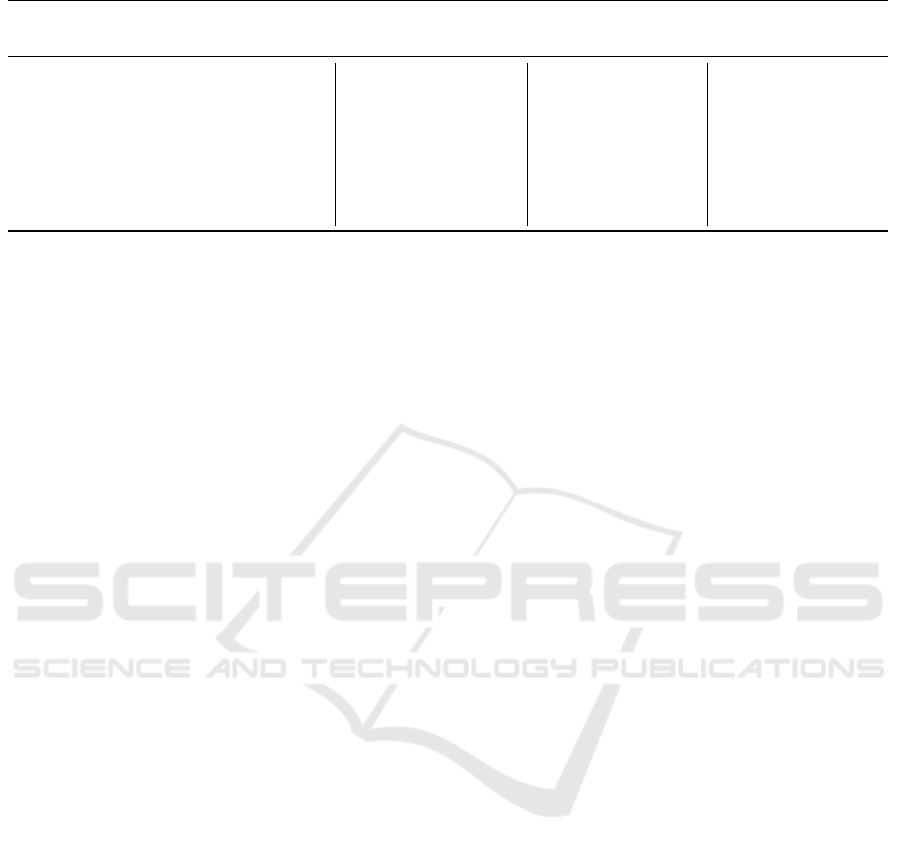
Table 2: Absolute numbers of detected design patterns.
Program Name Composite Observer Strategy Template Method
∑ ∑
C
∑
D
∑ ∑
C
∑
D
∑ ∑
C
∑
D
∑ ∑
C
∑
D
BerkeleyDB
12 1 0 2516 – – 55 – – 94 11 2
ChatSystem
– – – – – – – – – – – –
FeatureAMP
– – – 74 7 7 1 – – – – –
GameOfLife
– – – 2 1 1 3 1 1 – – –
GPL
– – – 12 – – – – – 1 – –
Notepad
– – – – – – – – – – – –
Violet
5 1 0 133 – – 7 – – 12 9 9
The results for the Strategy pattern also contain the results for the structurally equivalent Objectifier pattern.
occurred, especially for the Observer pattern. Nevert-
heless, the majority of the design patterns detected by
our analysis is implemented across multiple features.
As an example, we present the results of the Ob-
server pattern in the SPL FeatureAMP, a feature-
oriented audio player. In this case, seven decompo-
sed instances of the Observer pattern occurred. All of
them are used to notify objects about events concer-
ning the playback of a song, such as the PlayLis-
tener, which is notified when a song starts.
While all existing XYZListeners implement
the same Observer interface and are registered at
the same Subject, we regard them as different in-
stances of the Observer pattern because each of them
has their own add/remove and notify methods.
The rest of the overall number of detections are dupli-
cate matches of these seven instances. Each of the in-
volved methods only references the Observer inter-
face instead of the concrete XYZListener, which
is why the automated detection cannot distinguish be-
tween the methods for the XYZListeners.
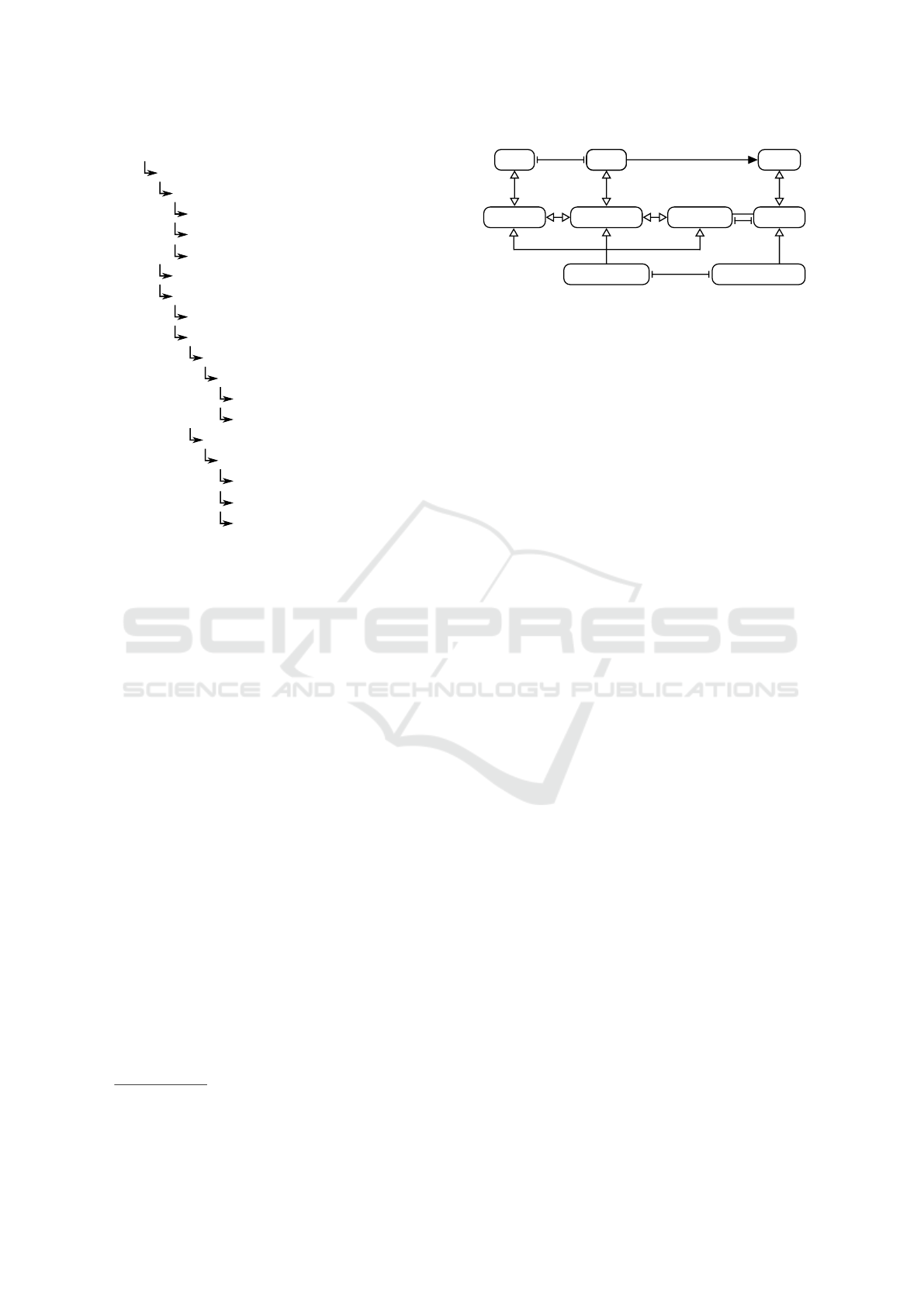
Figure 10 illustrates an excerpt of the feature mo-
del of FeatureAMP consisting of all features relevant
for the decomposed implementation of the Observer
pattern. The features are annotated with the respective
roles of the Observer pattern as defined in Figure 5.
Many features are participating in implementing the
Observer pattern. Furthermore, the roles of the Ob-
server pattern are distributed across the feature model.
Listing 1 shows an exemplary implementation of the
Observer pattern in FEATUREAMP. The roles of the
pattern are annotated using comments.
Combining both Figure 10 and Listing 1, the
way of decomposing the Observer pattern in FEA-
TUREAMP becomes evident. In the base feature
BASE_FEATUREAMP, an abstract class playing all
subject-related roles SubjectAdd (SA), SubjectNotify
(SN) and SubjectField (SF) are introduced as well as
an interface playing the Observer (O) role. Hence,
the abstractions implementing the basic functiona-
lity of the event notification are all introduced within
the (mandatory) base feature. In the subfeatures
of FILE_SUPPORT, MP3 and OGG, two classes
playing the ConcreteSubject (CS) role are introdu-
ced, which both inherit from the abstract class playing
the subject-related roles. In the feature model in Fi-
gure 10, the seven different occurrences of Concrete-
Observers are denoted using numbers from 1–7. Each
number represents an implementation of the common
Observer interface, while multiple instances of each
implementation in different features may exist.
All other decomposed findings for all patterns
look similar and only vary subtly. In all cases, the ab-
stractions introducing the general concepts of the pat-
tern are encapsulated within one single feature whe-
reas concrete implementations of these abstractions
are decomposed along multiple features. While con-
crete implementations of the Strategy pattern are en-
capsulated within a feature group (similar to Con-
creteSubjects), concrete implementations of the Tem-
plate Method pattern are distributed across the entire
feature model (similar to ConcreteObservers).
5.3 Discussion
The results of the case study suggest that design pat-
terns are frequently and, if so, similarly decomposed.
In this section, we discuss the results and answer the
research questions.
The results shown in Table 2 contain a high num-
ber of false positives, especially for the Observer pat-
tern. In cases of the BERKELEYDB and VIOLET, all
detected matches have been identified as false posi-
tives by manual elimination. We argue that a high
number of false positives results from the structural
descriptions of the respective design pattern being too
unspecific for static analysis. As a design pattern is
mainly described by dynamic object collaborations,
the derived structural conditions cannot be too spe-
cific because that could eliminate genuine matches.
Especially for the Observer pattern, mostly dynamic
conditions exist as the pattern is used for object de-
MOMA3N 2018 - Special Session on Model Management And Analytics
738
BASE_FEATUREAMP
PLAYER_BAR FILE_SUPPORT
MP3 OGG
ID3_TITLE PROGRESS
TITLE_TIME PROGRESS_BAR
VOLUME_CONTROL PLAYLIST
PLAYER_CONTROL
SHUFFLE_REPEAT
QUEUE_TRACK
SHOW_COVER
SA
SN SF
O
CS CS
1
3
4
6
1 1 1 1
7
7
1
2
1
2
7 7 7
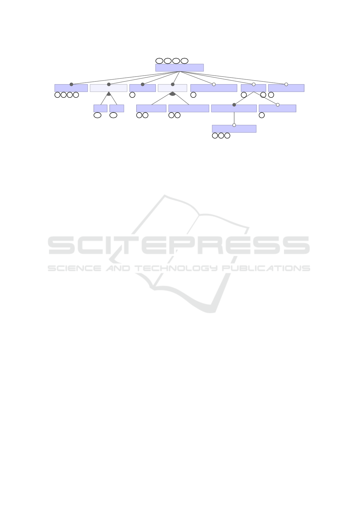
Figure 10: Extract of the feature model of FeatureAMP showing all features relevant to the observer patterns. Annotations
show the roles of the decomposed observer pattern (cf. Figure 5) they introduce. SA: SubjectAdd, SN: SubjectNotify,
SF: SubjectField, O: Observer, CS: ConcreteSubject, Numbers denote the different occurrences of ConcreteObservers.
coupling. Using static analysis, such unspecific struc-
tural descriptions result in the majority of matches
constituting the same structure as an instance of the
respective pattern. However, the semantics of the re-
spective design pattern may not be fulfilled.
We argue that an encapsulation of the abstractions
and a decomposition of concrete implementations is
reasonable. The different subject roles (i.e., Subject-
Field, SubjectAdd and SubjectNotify) can be seen as
one unit of functionality. Introducing a list of obser-
ver objects would not be sensible if it is never used.
Furthermore, an observer interface is not sensible wit-
hout a subject to observe. Hence, in the findings,
there is always a feature that encapsulates the entire
functionality required to realize event notification for
the respective application scenario (e.g., updating the
view on model changes). This argumentation holds
for other design patterns as well. Decomposing ab-
stract implementations that realize the basic functio-
nality of the pattern is infeasible as they introduce the
functionality together.
The decomposition takes place for the concrete ro-
les of the pattern – in this case of both subject and ob-
server. While the ConcreteSubject in GameOfLife is
also introduced in one feature together with the Sub-
ject and Observer roles, in FeatureAMP, two Con-
creteSubject roles are introduced in two different fe-
atures of a mandatory or-group. Hence, if the Obser-
ver pattern is introduced, the existence of at least one
ConcreteSubject role is necessary.
A ConcreteObserver does not add to the functi-
onality of the Subject but rather to another functio-
nality that depends on the state of a Subject. Hence,
there might be variants in which no dependent objects
exist. Due to this reason, ConcreteObservers are in-
troduced in other features than the general event noti-
fication functionality. Moreover, many ConcreteOb-
servers are enclosed by optional features, especially
in FeatureAMP (cf. Figure 10). As it depends on the
state of a Subject, the general event notification has to
exist for the ConcreteObserver to be introduced.
This argumentation holds for other patterns as
well. Decomposing concrete roles of the pattern ab-
stractions is feasible because they either introduce si-
milar, interchangeable behavior (such as Concrete-
Subject) or they do not contribute to the main functi-
onality but rather extend it by new features that de-
pend on the main functionality (such as ConcreteOb-
servers). With these results and the above argumenta-
tion, it is possible to answer the research questions.
RQ1: The observer pattern implementation in Fea-
tureAMP is distributed across the entire feature mo-
del. Although the abstractions (i.e., the Subject and
Observer) are all encapsulated within one single fea-
ture, both ConcreteSubjects are introduced within dif-
ferent features. Several features introduce Concrete-
Observers while sometimes introducing more than
one. Other design patterns are decomposed in a si-
milar way. Abstractions are always encapsulated by
a single feature. Concrete strategies of the Strategy
pattern are encapsulated in separate features that are
enclosed by a feature group. Concrete implementa-
tions of the Template Method pattern are distributed
across the entire feature model.
RQ2: The abstractions (i.e., Subject and Observer)
are introduced in the base feature of FeatureAMP and
mandatory for each possible variant. Using a manda-
tory or-group, the two very similar ConcreteSubjects
are introduced. This means that at least one of these
implementations exists in each possible variant.
While ConcreteSubjects are introduced in a fea-
ture group, no regularity seems to exist in which Con-
creteObservers are introduced. Different Concrete-
Observers are implemented across the entire feature
model. The same holds for concrete implementations
of the Template Method pattern. We argue, that such
Detecting and Describing Variability-Aware Design Patterns in Feature-Oriented Software Product Lines
739

Feature BASE_FEATUREAMP
public interface Listener<T> { // Observer
public void update(T object);
}
public abstract class AbstractAudioController
implements AudioController {
// SubjectField
protected LinkedList
<Listener<AudioController>> playListeners;
// SubjectAdd
public void addPlayListener(
Listener<AudioController> l) {
this.playListeners.add(l);
}
// SubjectNotify
protected void notifyPlayListeners() {
for (Listener<AudioController> l :
this.playListeners) {
l.update(this);
}
}
}
Feature MP3
public class Mp3Controller // ConcreteSubject
extends AbstractAudioController {
public void play() {
/
*
...
*
/
this.notifyPlayListeners();
}
}
Feature PLAYER_BAR
public class PlayerBar {
class PlayListener // ConcreteObserver
implements Listener<Controller> {
public void update(AudioController a) {
playButton.setEnabled(false);
pauseButton.setEnabled(true);
stopButton.setEnabled(true);
}
}
}
Listing 1: Observer pattern in FEATUREAMP.
a decomposition results from the functionality added
by the features. ConcreteObservers may add any kind
of functionality and only depend on a subject. They
do not extend the subject’s functionality. On the ot-
her hand, as ConcreteSubjects, concrete strategies of
the Strategy pattern are introduced in single features
encapsulated by one feature group. The reason is that
concrete strategies only add to the functionality des-
cribed by the abstract strategy.
From these results, an FRM can be derived. Fi-
gure 9 already depicted the FRM for the Observer
pattern, derived from the results of this case study.
This FRM encapsulates the abstractions of the Obser-
ver pattern in a single feature, whereas the concrete
roles are introduced in different features that depend
on the abstractions being present.
5.4 Threats to Validity
As the results depend on the selection and setup of the
case study, in the following, we list threats to validity.
5.4.1 Construct Validity
No formal standard description of the characteristics
of a design pattern exists (Dong et al., 2009). Mo-
reover, each pattern can be implemented in a variety
of ways. However, we formalized the design patterns
according to a general understanding of the patterns
adopted from literature.
5.4.2 Internal Validity
We might reject actual instances of design patterns be-
cause of too much deviation from our characteristics.
The static detection technique depends on the descrip-
tion of design pattern characteristics. Nevertheless,
we detected multiple genuine design pattern instan-
ces.
5.4.3 External Validity
We only analyzed a small set of SPLs and design pat-
terns, which might impair generalizability and repro-
ducibility of our results. However, we argue that we
cover a variety of sizes and different domains. This
way, the probability of detecting design patterns and
also the generalizability and reproducibility of the re-
sults is increased. Moreover, most of the other de-
sign patterns do not implement variability. Hence, we
argue that with this set of design patterns, we cover
common and important variability patterns. Further-
more, our approach is extensible with more patterns.
6 RELATED WORK
With this work, we continue the effort on learning
how design patterns affect design in FOP and how
the use of FOP affects the implementation of design
patterns (Schuster and Schulze, 2012; Schuster et al.,
2013; Schuster, 2014; Seidl et al., 2017). We ex-
tended this work by introducing a model-based ana-
lysis method for detecting variability-aware patterns
and employing FRMs for their description.
After (Gamma et al., 1994) introduced design pat-
terns, there has been ongoing research, documenting
new patterns, e.g., the Objectifier (Zimmer, 1995) or
MOMA3N 2018 - Special Session on Model Management And Analytics
740

Extension Objects (Gamma, 1996) patterns. More-
over, the application of patterns (Beck et al., 1996)
and their relationships (Zimmer, 1995) have been ana-
lyzed. Furthermore, design patterns have been des-
cribed as role models (Riehle, 1996), however, not
for decompositions in SPLs. We contribute to the
overall research on design patterns by documenting
feature-oriented variants of patterns that are decom-
posed across multiple features.
(Hannemann and Kiczales, 2002) already modula-
rized design patterns in the context of ASPECTJ (Ki-
czales et al., 2001), an extension to Java allo-
wing Aspect-Oriented Programming (Kiczales et al.,
1997). They reasoned on the modularization of de-
sign patterns, pointing out potential benefits com-
pared to standard pattern implementations. Howe-
ver, they concentrated on cross-cutting characteristics
of design patterns and did not investigate the actual
usage of decomposed pattern instances.
(Kolesnikov, 2011) developed FUJI, a fully-
fledged compiler and AST for feature-oriented JAVA
code. FUJI annotates each element with informa-
tion on which feature introduces the element, but not
which features refine it. Our 150% ASG does not
compose the SPL but rather parses the separate fea-
ture modules and resolves all references to elements
defined in other features. Hence, the 150% ASG faci-
litates family-based analysis.
(Kästner et al., 2011) also perform variability-
aware parsing of realization artifacts. However, they
focus on parsing realization artifacts containing anno-
tative variability, whereas we focus on compositional
approaches. These approaches face elementary diffe-
rent challenges: (Kästner et al., 2011) parse 150% re-
presentations that contain elements and references for
all possible variants. In contrast, we parse different
feature modules whose references have to be resolved
while respecting variability.
Extensive research exists on the topic of design
pattern detection (Dong et al., 2009; Rasool and
Streitferdt, 2011). For example, (Heuzeroth et al.,
2003) capture the specific characteristics of design
patterns that describe the minimal structural require-
ments. (Tsantalis et al., 2006) use graph pattern ma-
tching combined with a similarity scoring algorithm
to identify graph structures that are exact representa-
tions or similar structures of a specific design pattern.
As no design pattern detection for SPLs exists, we
developed a static design pattern detection technique
based on both approaches tailored to SPLs.
7 CONCLUSION
In this work, we presented and applied a model-based
analysis method to determine the variability-aware
usage of design patterns in the context of the source
code of FOP-based SPLs. Moreover, we introduced
Family Role Models (FRM) as a modeling notation
based on role modeling, which can be used to con-
strain the decomposed usage of design patterns. The
main observation of the conducted case study is that
abstract parts of design patterns, which introduce the
general concept of the pattern, are always introduced
within one single feature. In contrast, concrete parts
of design patterns, such as concrete implementations
of Observers or Strategies, are often decomposed al-
ong features. For the Observer and Template Method
patterns, features introducing concrete parts are dis-
tributed across the entire feature model, whereas, for
the Strategy (and Objectifier) pattern, concrete parts
are introduced in one feature group.
A decomposition of specific design patterns ap-
pears to increase modularity and reuse by decoupling
specific implementations from abstraction. Fine-
grained customization is allowed by exploiting vari-
ability offered by design patterns.
In the future, our efforts in variability-aware pat-
tern mining may produce more insights into common
practice of realizing SPLs using design patterns. Ba-
sed on this, guidelines for best practices in imple-
menting SPLs using modularized patterns may be de-
rived. Moreover, entirely new design patterns may be
revealed, dedicated to realizing variability.
REFERENCES
Alves, V., Gheyi, R., Massoni, T., Kulesza, U., Borba, P.,
and Lucena, C. (2006). Refactoring Product Lines.
In Proceedings of the 5th International Conference on
Generative Programming and Component Engineer-
ing, pages 201–210, New York, NY, USA. ACM.
Apel, S., Batory, D., Kästner, C., and Saake, G. (2013).
Feature-Oriented Software Product Lines. Springer.
Apel, S. and Beyer, D. (2011). Feature Cohesion in Soft-
ware Product Lines: An Exploratory Study. In Pro-
ceedings of the 33rd International Conference on Soft-
ware Engineering, pages 421–430. IEEE.
Apel, S., Kastner, C., and Lengauer, C. (2009). FEATU-
REHOUSE: Language-Independent, Automated Soft-
ware Composition. In Proceedings of the 31st Inter-
national Conference on Software Engineering, pages
221–231, Washington, DC, USA. IEEE Computer So-
ciety.
Apel, S. and Kästner, C. (2009). An Overview of Feature-
Oriented Software Development. Journal of Object
Technology, 8(5):49–84.
Detecting and Describing Variability-Aware Design Patterns in Feature-Oriented Software Product Lines
741

Batory, D., Sarvela, J. N., and Rauschmayer, A. (2004).
Scaling Step-Wise Refinement. IEEE Transactions on
Software Engineering, 30(6):355–371.
Beck, K., Crocker, R., Meszaros, G., Vlissides, J., Coplien,
J. O., Dominick, L., and Paulisch, F. (1996). Indus-
trial Experience with Design Patterns. In Proceedings
of the 18th International Conference on Software En-
gineering, pages 103–114. IEEE Computer Society.
Clements, P. and Northrop, L. (2001). Software Product
Lines – Practices and Patterns. Addison-Wesley.
Czarnecki, K. and Eisenecker, U. W. (2000). Genera-
tive Programming: Methods, Tools, and Applicati-
ons. ACM Press/Addison-Wesley Publishing Co.,
New York, NY, USA.
Dong, J., Zhao, Y., and Peng, T. (2009). A Review of De-
sign Pattern Mining Techniques. International Jour-
nal of Software Engineering and Knowledge Engi-
neering, 19(06):823–855.
Gamma, E. (1996). The Extension Objects Pattern. In Pro-
ceedings of the 1996 Conference on Pattern Langua-
ges of Programs.
Gamma, E., Helm, R., Johnson, R., and Vlissides, J.
(1994). Design Patterns: Elements of Reusable
Object-Oriented Software. Addison-Wesley Longman
Publishing Co., Inc., Boston, MA, USA.
Hannemann, J. and Kiczales, G. (2002). Design Pattern
Implementation in Java and AspectJ. ACM SIGPLAN
Notices, 37(11):161–173.
Heuzeroth, D., Holl, T., Hogstrom, G., and Lowe, W.
(2003). Automatic Design Pattern Detection. In Pro-
ceedings of the 11th IEEE International Workshop on
Program Comprehension, pages 94–103.
Kang, K. C., Cohen, S. G., Hess, J. A., Novak, W. E.,
and Peterson, A. S. (1990). Feature-Oriented Domain
Analysis (FODA) Feasibility Study. Technical report,
DTIC Document.
Kästner, C., Giarrusso, P. G., Rendel, T., Erdweg, S., Os-
termann, K., and Berger, T. (2011). Variability-aware
parsing in the presence of lexical macros and conditi-
onal compilation. SIGPLAN Not., 46(10):805–824.
Kiczales, G., Hilsdale, E., Hugunin, J., Kersten, M., Palm,
J., and Griswold, W. (2001). An Overview of As-
pectJ. In Knudsen, J., editor, ECOOP 2001 – Object-
Oriented Programming, volume 2072 of Lecture No-
tes in Computer Science, pages 327–354. Springer
Berlin Heidelberg.
Kiczales, G., Lamping, J., Mendhekar, A., Maeda, C., Lo-
pes, C., Loingtier, J.-M., and Irwin, J. (1997). Aspect-
Oriented Programming. In Ak¸sit, M. and Matsuoka,
S., editors, ECOOP’97 — Object-Ori-ented Program-
ming, volume 1241 of Lecture Notes in Computer
Science, pages 220–242. Springer Berlin Heidelberg.
Kolesnikov, S. (2011). An Extensible Compiler for Feature-
Oriented Programming in Java.
Kästner, C., Apel, S., and Ostermann, K. (2011). The Road
to Feature Modularity? In Proceedings of the 15th
International Software Product Line Conference, Vo-
lume 2, pages 5:1–5:8, New York, NY, USA. ACM.
Pohl, K., Böckle, G., and Van Der Linden, F. (2005). Soft-
ware Product Line Engineering: Foundations, Princi-
ples, and Techniques. Springer.
Prehofer, C. (1997). Feature-Oriented Programming: A
Fresh Look At Objects. In Proceedings of the 11th
European Conference on Object-Oriented Program-
ming, pages 419–443. Springer.
Rasool, G. and Streitferdt, D. (2011). A Survey on De-
sign Pattern Recovery Techniques. IJCSI Internati-
onal Journal of Computer Science Issues, 8(2):251–
260.
Reenskaug, T., Wold, P., and Lehne, O. A. (1996). Wor-
king with Objects: The OOram Software Engineering
Method. Manning Greenwich.
Riehle, D. (1996). Describing and Composing Patterns
using Role Diagrams. In White Object-oriented Nig-
hts: Proceedings of the 1st International Conference
on Object-Oriented Technology, volume 96.
Riehle, D. (1997). A Role-Based Design Pattern Catalog of
Atomic and Composite Patterns Structured by Pattern
Purpose. Technical report, Ubilab Technical Report
97.1. 1. Zürich, Switzerland: Union Bank of Switzer-
land.
Riehle, D. and Gross, T. (1998). Role Model Based Frame-
work Design and Integration. In Proceedings of the
13th ACM SIGPLAN Conference on Object-oriented
Programming, Systems, Languages, and Applications,
pages 117–133, New York, NY, USA. ACM.
Schaefer, I., Rabiser, R., Clarke, D., Bettini, L., Benavides,
D., Botterweck, G., Pathak, A., Trujillo, S., and Vil-
lela, K. (2012). Software Diversity: State of the Art
and Perspectives. International Journal on Software
Tools for Technology Transfer, 14(5):477–495.
Schuster, S. (2014). Pattern-Based Software Product
Line Design using Role Modeling. Diploma thesis,
Technische Universität Braunschweig.
Schuster, S. and Schulze, S. (2012). Object-Oriented De-
sign in Feature-Oriented Programming. In Procee-
dings of the 4th International Workshop on Feature-
Oriented Software Development, pages 25–28, New
York, NY, USA. ACM.
Schuster, S., Schulze, S., and Schaefer, I. (2013). Structural
Feature Interaction Patterns: Case Studies and Guide-
lines. In Proceedings of the 8th International Works-
hop on Variability Modeling of Software-Intensive Sy-
stems, pages 14:1–14:8, New York, NY, USA. ACM.
Seidl, C., Schuster, S., and Schaefer, I. (2017). Ge-
nerative Software Product Line Development using
Variability-Aware Design Patterns. Computer Lan-
guages, Systems & Structures, 48(Supplement C):89
– 111. Special Issue on the 14th International Confe-
rence on Generative Programming: Concepts & Ex-
periences (GPCE’15).
Smaragdakis, Y. and Batory, D. (2002). Mixin Layers: An
Object-Oriented Implementation Technique for Re-
finements and Collaboration-Based Designs. ACM
Transactions on Software Engineering and Methodo-
logy, 11(2):215–255.
Tsantalis, N., Chatzigeorgiou, A., Stephanides, G., and Hal-
kidis, S. (2006). Design Pattern Detection Using Si-
milarity Scoring. Software Engineering, IEEE Tran-
sactions on, 32(11):896–909.
Zimmer, W. (1995). Relationships between Design Patterns.
Pattern Languages of Program Design, 1:345–364.
MOMA3N 2018 - Special Session on Model Management And Analytics
742
