
Iterative Process for Generating ER Diagram from Unrestricted
Requirements
Muhammad Javed and Yuqing Lin
School of Electrical Engineering and Computing, The University of Newcastle, Newcastle, NSW, Australia
Keywords: Entity Relationship Diagram, General Requirements, User Stories, Use Case Specification, Natural Language
Processing, Type Dependencies.
Abstract: Requirements analysis for generating a conceptual model such as an Entity Relationship Diagram (ERD) is
an essential task in software development life cycle. In this paper, we are presenting a Natural Language
Processing (NLP) based approach to generate the ERD from requirements in an unrestricted format such as
general requirements, user stories or Use Case Specification (UCS). To assess the performance and
correctness of the proposed technique, we compare our approach with existing automated techniques by
processing the same requirements. The preliminary results show a significant improvement.
1 INTRODUCTION
The major portion of the software industry is
information systems that are being used by all types
of organizations (Uduwela and Wijayarathna, 2015).
Designing a database system from requirements is an
important subsection of a software development life
cycle (Omer and Wilson, 2015. Meziane and Vadera,
2004. Btoush and Hammad, 2015), normally
resulting in an Entity Relationship Diagram (ERD).
Requirements related to the software are generally
collected in Natural Language (NL) (Neill and
Laplante, 2003). Analysis of requirements is a
difficult task due to the drawbacks of NL (Elbendak
et.al, 2011). Major drawbacks of NL include
ambiguity, inconsistency, and redundancy (Lucassen
et.al, 2017. Elbendak et.al, 2011). These drawbacks
make the automated ERD extraction process lengthy
and error prone (Btoush and Hammad, 2015). The
accuracy and efficiency become the main challenges
while transforming, as stated by Tjoa and Berger
(1993) the transformation is indeed challenging.
Another factor we have to deal with during the
transformation is how the requirements are presented.
Based on the development approaches being used,
requirements may be written in different ways, for
instance common methods of presenting
requirements include but are not limited to, general
requirements, UCS or User Stories etc. Furthermore,
depending on the organizational practices and
standards, different templates are being used, for
instance, in IEEE830:1998 or in ISO/IEC/IEEE
29148:2011. Even if we consider only the UCSs, the
engineers are using different templates. The most
unpredictable and unrestricted requirements are, from
the inconsistent resources, such as User Stories,
UCSs. This will require extra effort to detect the
requirements format, sentence structure.
In this paper, we are presenting an automated NLP
based approach to generate ERDs from unrestricted
requirements formats i.e. general requirements, UCSs,
or User Stories. Our proposed approach is not
restricted to a specific template of UCS. To achieve
this goal, we considered the Type Dependencies (TDs)
of each sentence. We have defined rules based on new
and enhanced TDs to be used in our approach.
Furthermore, our approach has multiple iterations. In
the first iteration, TD of the processed sentences are
identified to generate entities and attributes, both in
moving forward and reverse manner. In the second
iteration, relationships and in the third iteration the
cardinalities obtained.
By analyzing the flow of data and interaction
between entities, we try to refine the relationships
between entities in the ERD if no relation exist. The
accuracy and efficiency of this automated approach
have been proved by comparing the results with the
existing automated techniques.
In the remainder of this paper, section 2 contains
an overview of our proposed approach and a detailed
explanation of TDs. In section 3, we presented case
192
Javed, M. and Lin, Y.
Iterative Process for Generating ER Diagram from Unrestricted Requirements.
DOI: 10.5220/0006778701920204
In Proceedings of the 13th International Conference on Evaluation of Novel Approaches to Software Engineering (ENASE 2018), pages 192-204
ISBN: 978-989-758-300-1
Copyright
c
2020 by SCITEPRESS – Science and Technology Publications, Lda. All rights reserved
studies. Section 4 presents a detailed literature review.
Section 5, presents a preliminary evaluation of
accuracy and efficiency of the proposed approach by
comparing it with existing automated tools. At finally,
a conclusion and future works are presented in section
6.
2 PROPOSED APPROACH
In this section, we are presenting the framework and
the main artifacts extraction procedure of our
proposed approach. For evaluating the proposed
approach, a tool has been developed in Visual C#
based on Stanford CoreNLP 3.8 APIs to generate the
ERD.
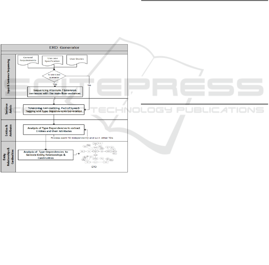
Fig. 1 shows the overview and steps followed in
order to generate an ERD from unrestricted
requirement specifications using the NLP based
technique.
Figure 1: Conceptual Diagram of Proposed Approach.
2.1 Sentence Sequencing
UCSs contains functional requirements with a
sequence of actions performed by the actors and the
system (Thakur and Gupta, 2017). Commonly, a UCS
contains sections such as name, description, pre-
condition, post-condition, actor and main flow.
However, alternate flow and exceptions are often
presented differently. Different formats for
referencing sentences in alternate or extension
sections can be used (Siqueira and Silva, 2011). For
instance, the sentence in the main flow section could
contain the references to flows in the extension
sections or be referred to the extension or alternate
sections. Our tool will scan the whole UCSs
document to obtain a flow by combining the
sentences in alternative or extension sections along
with appropriate sentences in the main flow. As we
are not restricting the UCS template, sequencing of
sentences is an important task to find branching flows
from the alternate or extension sections.
Based on the studies of various sentence
referencing formats in UCSs we designed the
following algorithm for sequencing the sentences in
alternative and extension sections with respect to the
main flow in UC.
1.
2.
3.
4.
5.
6.
7.
8.
9.
10.
11.
12.
13.
14.
15.
16.
17.
18.
Foreach Main.Sentence in Main_Flow
Process_List.add(Main.Senetnce)
If Main.Sentence.Contains (Reference)
If Refrence.Type = “Alternate”
Foreach Sentence in Alternate
If Sentence.Number = Reference.Number
Process_List.Add(Sentence)
End of if started at line# 6
End of foreach loop started at line # 5
Else If Refrence.Type = “Extension”
Foreach Sentence in Extension
If Sentence.Number = Reference.Number
Process_List.Add(Sentence)
End of if started at line# 12
End of foreach loop started at line #
11
End of if started at line# 4
End of if started at line# 3
End of foreach loop started at line# 1
Figure 2: Algorithm for sequencing the sentences in
Alternative and Extension with Main flow.
In the above sentences sequencing algorithm, the
loop at line # 1 is to add main sentences in the
processing list one-by-one. The conditional statement
at line # 3 is to check whether the main sentence
contains any reference to the alternative or extension
sections, and if so, the sentence will be added for
processing with the main sentence from line # 4 to
line #16.
2.2 Sentence Analysis
2.2.1 Tokenizing, Lemmatizing and Part of
Speech (POS) Tagging
Sentence analysis is the basic and fundamental step
of NLP. In this step, we process each sentence for
tokenizing, lemmatizing (converting each word to its
basic form e.g. from played to play) and POS-tagging
using Stanford CoreNLP 3.8 APIs. For accurate
processing using Stanford APIs, each sentence should
end a with full stop / period sign (.), and should not
Iterative Process for Generating ER Diagram from Unrestricted Requirements
193
contain a period sign and hyphen (-) within the
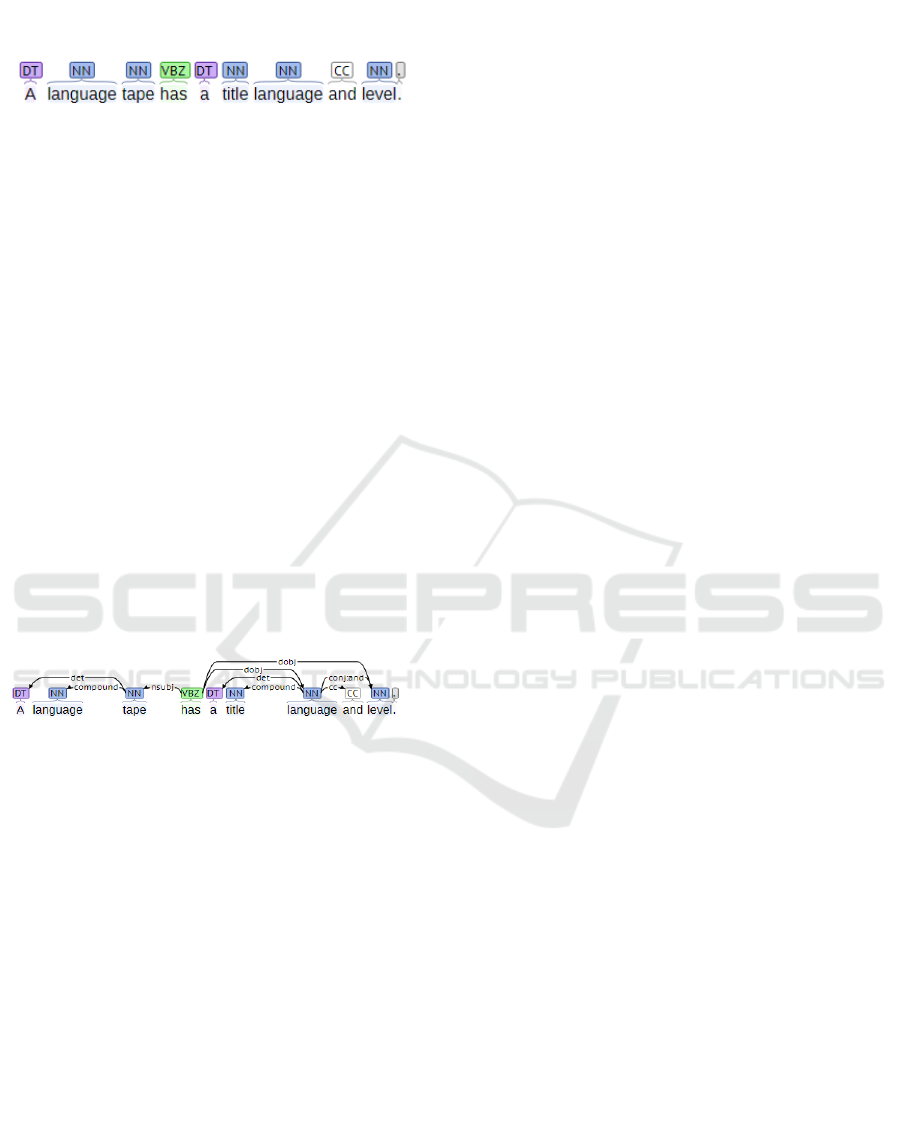
sentences e.g. “
A language tape has a title language and
level.”
Figure 3: Visual representation of POS –tags using Stanford
CoreNLP web API.
2.2.2 Type Dependency Generation
Type dependency represents the syntactic
relationships between words of a sentence (Marneffe
and Manning, 2008). Each TD contains a pair of
words based on the grammatical relation. For
instance, the following are the TDs generated from
the sentence used in our previous example. The first
TD is root to represent the root of the sentence with a
fake word “ROOT-0” and a verb “has”. Second TD
det is a determiner relationship of a noun and its
determiner. Number with each word in TDs
represents the word’s sequence number in a sentence.
Marneffe and Manning, (2008) explained TDs in
detail.
root(ROOT-0, has-4), det(tape-3, a-1), compound(tape-3,
language-2), nsubj(has-4, tape-3), det(language-7, a-5),
compound(language-7, title-6), dobj(has-4, language-7),
cc(language-7, and-8), dobj(has-4, level-9),
conj:and(language-7, level-9), punct(has-4, .-10)
Figure 4: Visual representation of TDs using Stanford
CoreNLP.
2.3 Analysis of Type Dependencies
2.3.1 Entities and Attributes Extraction
In this subsection, we illustrate how to extract
potential entities and attributes using the Type
Dependency based Rules (TDRs). In these rules,
PrevTD represents the Previous TD while nextTD is
for next TD with respect to the current TD that is
under consideration. Basic_Attrib represents the basic
forms of attributes e.g. name, number, no, type,
address, level, date, time (Omar et.al, 2004). During
the process, we present a pair of words in TD with
letters A and B as TD(A, B). We use (TDR#) to refer
the TDR included in appendix of the paper.
We define the TDRs by analyzing the TDs
individually as well as in relation to the other TDs
within the sentence. This step is the first iteration of
TDs processing. To make our rules easy to
understand, we presented them in a similar format as
used in (Thakur and Gupta, 2017) e.g. nsubj(A,B).
TDRs used for extracting entities and attributes are
illustrated in Appendix in algorithmic format.
From the existing work, we conclude that
researchers are agreed in that noun, especially
common nouns (Thakur and Gupta, 2017. Chen,
1976. Song et.al, 1995. Omar et.al, 2004) and Gerund
(Chen, 1976. Omar et.al, 2004) are potential entities.
Attributes appear as noun, adjective (Thakur and
Gupta, 2017. Chen, 1976. Song et.al, 1995. Omar
et.al, 2004), possessive apostrophe (Harmain and
Gaizauskas, 2003. Omar et.al, 2004) or with
indicators e.g. no, name, date etc. (Omar et.al, 2004).
It is worth mentioning here that not all nouns are the
candidate for entities or attributes. For example, the
database, system, company, record etc. are not
candidates when listed in the requirements document
(Omar et.al, 2004).
This is a multi-iterative process. In each iteration
TDs are processed to generate the results. In this first
iteration, we try to generate entities and attributes by
applying TDRs. This is a two-way (forward and
backward) iteration. Once the entities and attributes
are extracted in the forward iteration, we then trace
back to check if an attribute extracted in a sentence
has sub-attributes in the following sentences. If sub-
attributes are found, then they will be inserted to
entities and removed from the attributes list.
Subject
Nouns appearing in the subject part of the sentence
are considered as the potential entity (Bajwa et.al,
2009. Omar et.al, 2004). (Lucassen et.al, 2017.
Thakur and Gupta, 2017. Arora et.al, 2016. Sagar and
Abirami, 2014. Ben et.al, 2016) tried to process nsubj
TD to extract entity while (Thakur and Gupta, 2017)
and (Ben et.al, 2016) also processed nsubjpass to
extract entities.
While processing sentences in different structures,
we found that the subject of the sentence may also
contain attributes. In TDs, the subject part of the
sentence is represented by nsubj(verb, noun). We
analyze the subject dependencies generated by
Stanford CoreNLP 3.8 APIs based on the type of
sentences, which will give us the nsubj: nominal
subject, nsubjpass: passive nominal subject, xsubj:
controlling subject, csubj: clausal subject, csubjpass:
clausal passive subject (Marneffe and Manning,
2008) of the sentence. It is known that nsubj and
nsubjpass contain entities or attributes while csubj
may have entities based on the clause of the sentence.
ENASE 2018 - 13th International Conference on Evaluation of Novel Approaches to Software Engineering
194

Dependency: nsubj(A, B) & nsubjpass(A, B)
If B part of these TDs is not the member of the basic
attributes set, then it is a potential entity (as illustrated
in TDR1 & TDR2).
Example: “Customer cancels the reservation.”
From this example along with other TDs we derive
nsub(cancels-2, Customer-1) having “Customer” as
an entity.
Example: “Offer is selected by the customer.”
From nsubjpass(selected-3, offer-1) “Offer”
extracted as entity.
Example: “ID and password are the basic
requirements to log in.”
TD nsubj(requirements-t, ID-1) contains attribute
“ID”
Compound nouns are represented by
compound(A, B) TD. If compound dependency
appears just before the nsubj or nsubjpass then by
combining both A and B parts of compound
dependency, entity or attribute will be generated.
Example: “Credit card has an expiry date.”
From TDs compound(card-2, credit-1) and
nsubj(has-3, card-1) “Credit Card” entity is
generated.
Example: “Expiry date of cash card entered by the
customer”
From TDs compound(date-2, expiry-1),
nsubj(entered-6, date-2) attribute “Expiry Date” can
be generated.
Object
Objects of the sentence contains entities (Lucassen
et.al, 2017. Thakur and Gupta, 2017. Arora et.al,
2016. Sagar and Abirami, 2014. Ben et.al, 2016).
Normally it is denoted by the TD dobj(Verb, Noun).
(Arora et.al, 2016. Sagar and Abirami, 2014. Ben
et.al, 2016) considered dobj TDs to extract entities,
while in the authors considered dobj and pobj TDs.
Dependencies: dobj (A, B), iobj(A, B) & pobj(A, B)
In this approach, we consider dobj: direct object, iobj:
indirect object and pobj: object of a preposition
(Marneffe and Manning, 2008) TDs representing the
object of a sentence.
If neither the B part contains basic attributes, nor
the action in part-A gives the sense of inputting
information (e.g. enter, inputted, save, add, has), nor
the previous TD is amod (adjectival modifier) then it
will be an entity as the adjective modifier contains
attributes. If compound also appears before any of the
TDs representing object then by combining nouns in
the compound, the entity will be generated (TDR3).
Example: “Customer cancels the reservation.”
From dobj(cancels-2, reservation-4) entity
“Reservation” is generated.
“Customer selected credit card for the payment.”
compound(card-4, credit-3), nsubj(selected-2, card-
4) have entity “Credit Card”.
If either the B part of object TD contains basic
attribute or the action in part-A in the sense of
inputting information or the previous TD is amod
then it will be an attribute. If the previous TD is amod
or compound then the attribute will be generated by
combining the A and B parts of the Previous TDs (see
TDR4 & TDR5 in Appendix A.1).
Example: “Customer enters phone number”
compound(phone-4, number-3), dobj(enters-2,
number-4) gives “Phone Number” as an attribute.
Example: “Customer enters first and last name and
address”
From amod(name-4, first-3), dobj(enters-2, name-4)
amod(name-7, last-6), dobj(enters-2, name-7),
dobj(enters-2, address-9) attributes “first name, last
name and address” extracted.
Prepositions
Prepositions are used to represent the relationships
of a noun with other words within the sentences.
Dependency: nmod:of(A,B)
(Thakur and Gupta, 2017) mentioned that the A part
is an attribute and the B part is an entity. While we
found that if the A and B parts of TD nmod:of do not
belong to the set of basic attributes, then both will be
entities. If any one of them is an attribute, then the
other one will be an entity. If both belong to attributes
then, by combining A and B, an attribute will be
generated (TDR6 ).
Example: “Visitor selected type of the event.”
nmod:of(type-3, event-5) has attribute “Type” and
“Event” as an entity.
“Card of the customer has expiry date”
In nmod:of(card-1, customer-4) “Card” and
“Customer “ both are entities.
Example: “Visitor entered the date of birth.”
nmod:of(date-3, birth-5) contains “Date of birth” as
an attribute.
Dependency: nmod:in(A,B)
A is an attribute and B is an entity (TDR7). Thakur
and Gupta (2017) presented the same concept.
Example: “The system validates that customer has
enough funds in the account.”
In nmod:in(funds-8, account-11) “Fund” is an
attribute and “Account” is the entity.
Dependencies: nmod:to(A,B), nmod:for(A,B),
nmod:from(A,B), nmod:as(A,B)
In these TDs, B will be the potential entity (TDR8).
Example: “The system displays price to the
customer.”
Iterative Process for Generating ER Diagram from Unrestricted Requirements
195

From nmod:to(displays-3, customer-7) “Customer”
is the entity extracted.
Example: “system starts displaying video feed for the
coordinator.”
From nmod:for(displaying-3, coordinator-7) entity
“Coordinator” is extracted.
Example: “Information does not match received from
the witness.”
nmod:from(received-5, witness-7) has the entity
“witness”.
Example: “As a visitor, I can create a new account.”
nmod:as(create-7, visitor-3) contains “Visitor”
entity.
Dependencies: nmod:by(A,B), nmod:agent(A,B),
nmod:with(A,B)
Agents, indicates someone or something that
performs an action on the subject of the sentence
(Kienzle et.al, 2010).
If B part of the TDs does not belong to the set of
the basic attributes, then it will be an entity, otherwise
it will be an attribute (TDR9 ).
Example: “A branch is uniquely identified by the
branch_number.”
nmod:agent(identified-5, branch_number-7) contains
“branch_number” attribute.
“Name and address are entered by the customer”
nmod:by(entered-4, customer-7) has entity
“Customer”.
Appositional Modifier
The possessive form is to show the relationship
between nouns.
Dependency: nmod:poss(A,B)
A is attribute and B is an entity if it is a noun. Thakur
and Gupta (2017) considered possessive nouns TD
w.r.t to apostrophe. In our approach along with
possessive apostrophes, possessive determiners, and
possessive pronouns are also considered (TDR10).
Example: “Administrator enters customer’s address.”
In nmod:poss(address-5, customer-3) “Customer” is
an entity while “address” is an attribute.
“Witness provided his name.”
nmod:poss(name-4, his-7) contains “name ”
attribute.
Adjectival Modifier
An adjectival modifier is an adjective modifying the
meaning of a noun/noun phrase (Marneffe and
Manning, 2008).
Dependencies: amod(A,B)
If B is adjective and A is a noun, and A does not
belong to the set of basic attributes, then A will be an
entity. Otherwise, by combining A and B, an attribute
will be generated (TDR11). While (Thakur and
Gupta, 2017) considered A as an entity and B as an
attribute in all cases.
Example: “System assign the initial level of
emergency.” amod(level-5, initial-4) “initial level” is
an attribute.
“Coordinator determines that the witness is calling a
fake crisis.” amod(crisis-11, fake-10) “Crisis” is an
Entity.
Compound Noun
A compound noun is a noun in a noun phrase that
modifies the main noun (Marneffe and Manning,
2008).
Dependency: compound(A,B)
If this dependency does not appear before a subject or
object TD, then it will be considered independently.
If any of the A or B parts represent the basic attribute,
then the other will be an entity. If neither is
representing a basic attribute then by combining
them, an entity will be generated (TDR12).
Example: “Coordinator provides information
(witness ID, first name, last name, phone number, and
address).”
compound(ID-6, witness-5) contains “Witness ID”
attribute and “Witness” entity while
compound(number-12, phone-11) contains “Phone
Number” attribute.
“Customer paid by credit card.”
In compound(card-5, credit-4) has “credit card”
entity
.
Conjunction
A conjunction illustrates the relationship between two
elements by “and” and “Or” (Marneffe and Manning,
2008).
Dependency: conj:and(A,B) , conj:or(A,B)
If anyone or both of A & B are nouns and belong to
the set of the basic attributes, then these are also
attributes, otherwise they will considered entities
(TDR13 ).
Example: “Customer enters ID and password to
login.”
In Conj:and(ID-3, password-5) both are attributes.
Gerund
A noun converted from the verb by adding “-ing”. A
Gerund appears as a noun in different TDs (Marneffe
and Manning, 2008). Hence, while processing the
TDs gerund will also be processed.
Example: “System display the booking dates.”
In compound (dates-5, booking-4) “Booking” is an
entity.
ENASE 2018 - 13th International Conference on Evaluation of Novel Approaches to Software Engineering
196

Pronoun
A pronoun represents the most immediate actor/entity
so, in case of the pronoun, it will be replaced with the
previous external entity.
Examples: “User selects login option. He enters ID
and password.”
In this example, the pronoun of the second
sentence in nsubj(enters-2, He-1) is referring to the
subject noun of first of sentence “user” in
nsubj(selects-2, user-1). Hence, “He” will be replaced
with “User”.
Example: “As a visitor, I can create a new account.”
In this sentence TD nmod:as(create-7, visitor-3)
contains entity and TD nsubj(create-7, I-5) contains
pronoun. So, pronoun “I” will be replaced with
“visitor”.
2.4 Relationships Extraction
A verb, especially a transitive verb, represents the
relationships between entities (Chen, 1976. Song
et.al, 1995. Harmain and Gaizauskas, 2003.
Ambriola, and Gervasi, 2006). Verbs followed by
prepositions are relationships (Omar et.al, 2004).
In the second iteration, TDs are reconsidered to
find the relationship between entities. During this
iteration, TDs that have extracted entities will be
processed. The TDRs related to relationship
extraction are mentioned in the appendix A.2. In these
rules “E” represents the entities extracted in the
previous stage.
A dependency with an entity in one part and verb
in the second part will be compared with other TDs
having the same format. If any two dependencies
have the same verb, the verb will be considered a
relationship between the entities mentioned in the
compared TDs (TDR14 & TDR15).
Example: “Administrator manages branches.”
From nsub(manages-2, Administrator-1) &
dobj(manages-2, branches-3) “Administrator
(manages) Branches” generated.
Entities with preposition “of” will be connected
by the relationship “has” (TDR16 & TDR17).
Example: “Card of the customer has expiry date”
nmod:of(card-1, customer-4) gives “Customer (has)
card” relationship.
In case of the prepositions “to”, “in”, “for”, and
“from”, these will be attached to verb representing the
relationship between entities (TDR18 to TDR22 ).
While in case of the comparative modifier “as”, only
the verb will be used as a relationship (TDR23).
Example: “Customer add Items to the cart.”
From TDs nsubj(add-2, customer-1), dobj(add-2,
items-3) & nmod:to(add-2, cart-6) relationships
“Customer (add) items”, “items (add to) cart” and
“Customer (add to) cart” extracted.
In UCS sometime no direct relationship exists
between entities, i.e. relationships do not appear in
one sentence or do not share common verb. In this
case, we tried to find a relationship between entities
by the flow of data.
Example (sentences from a use case with TDs):
1. “Customer selects the date.”
root(ROOT-0, selects-2), nsubj(selects-2, customer-1),
det(date-4, the-3), dobj(selects-2, date-4), punct(selects-2, .-
5)
2. “System displays the available booking dates.”
root(ROOT-0, displays-2), nsubj(displays-2, system-1),
det(dates-6, the-3), amod(dates-6, available-4),
compound(dates-6, booking-5), dobj(displays-2, dates-6),
punct(displays-2, .-7).
In the above example “Customer” and “booking”
don’t have any direct relationship but considering the
flow model “customer” is selecting a date in the first
sentence that belongs to “booking” in next sentence
so, by the flow of data we got “Customer (selects)
booking” a multi-sentence relationship.
2.5 Cardinalities Extraction
Cardinality signifies how many instances of one
entity can be associated with the instances of another
entity. Cardinality can be extracted from articles by
tracking the special indicators. Special indicators
include but are not limited to many, more, each, all,
and every (Harmain and Gaizauskas, 2003. Omar
et.al, 2004). In this iteration, our tool will extract the
cardinality of entities. Rules related to cardinality
extraction are listed in appendix.
Adjective modifier (amod) dependencies having
an entity represents the cardinality. If the adjective
part of the dependency contains many; some; all;
more; every; first; or last, then cardinality will be N
(TDR24).
Example: “A store has many branches.”
amod(branches-5, many-4) contains the cardinality
‘N’.
Number modifier (nummod) dependencies
represent the maximum or minimum cardinality
number. If this number contains “at least” or
“minimum” as a prefix then cardinality will be N. If
this number contains the prefix “at most”, “limit”,
“maximum” or “no more than” then this number will
be the maximum cardinality (TDR25).
Example: “Branch must be managed by at most 1
manager.”
nummod(manager-10, 1-9) represents the cardinality
1.
Iterative Process for Generating ER Diagram from Unrestricted Requirements
197
A determiner (det) also represents the cardinality
of a subjective entity. If any special characters (i.e.
many, some, each, more), all appear as a determiner
with an entity then the cardinality will be N. If articles
“a/an” appear with an entity, the cardinality will be
one. In the case of the “the” entity in a singular form
then the cardinality will be one, but if the entity is in
plural form then the cardinality will be N (TDR26).
Example: “Each product has an expiry date.”
det (product-2, Each-1) illustrate cardinality “1.
An entity marked by part of speech can also help
to identify cardinality. For instance, if the entity is
marked with NNS (Plural Noun), it may represent N
cardinality while entities marked with NN and NP
may represent “1” cardinality, in case of the absence
of above cardinality marks.
3 CASE STUDIES
In this section, we present a walk-through of our
proposed approach. The requirements, UCSs and user
stories are taken from the published literature so that
we could compare the results in later section.
3.1 Case Study of Processing General
Requirements
(“Store Problem” from (Omer and Wilson, 2015. Al-
Safadi, 2009.))
A store has many branches. Each branch must be managed by at
most 1 manager. A manager may manage at most 2 branches. The
branch sells many products. Product is sold by many branches.
Branch employs many workers. The labour may process at most 10
sales. It can involve many products. Each Product includes product
code, product name, size, unit_cost and shelf_no. A branch is
uniquely identified by branch_number. Branch has name, address
and phone_number. Sale includes sale_number, date, time and
total_amount. Each labour has name, address and telephone.
Worker is identified by id.”
The input is in plain text format (i.e. a file with txt
extension). In the process, tokenization and
lemmatizing, POS and TDs of each sentence are
processed using Stanford CoreNLP 3.8. TDRs (as
mentioned in Appendix) are applied for extracting
entities and attributes. Table 1 contains the entities
extracted from the above requirements. The first
column represents the entities while the second
column contains the frequency of each entity. This
frequency illustrates that how many times each entity
appears in different TDs.
Table 1: Entities Extracted from Above Requirements.
Entities Fre
q
uenc
y
(w.r.t TDs)
Store 1
Branch 8
Manage
r
2
Product 6
Worke
r
2
Labou
r
5
Sale 2
Table 2 contains the attributes of respective
entities extracted by applying TDs rules.
Table 2: Entities with Attributes.
Entities Attributes
Produc
t
code , name , size , unit_cos
t
, shelf_no
Branch Branch_Number, name , address , Phone_numbe
r
Sale sale_numbe
r
, date , time , total_amoun
t
Labou
r
name , address , telephone
Worke
r
Id
After generating entities and attributes, in second
iteration. TDRs (as listed in Appendix) applied to
extract relationships. In this (third) iteration of TDs
processing, TDRs listed in Appendix A.3 applied to
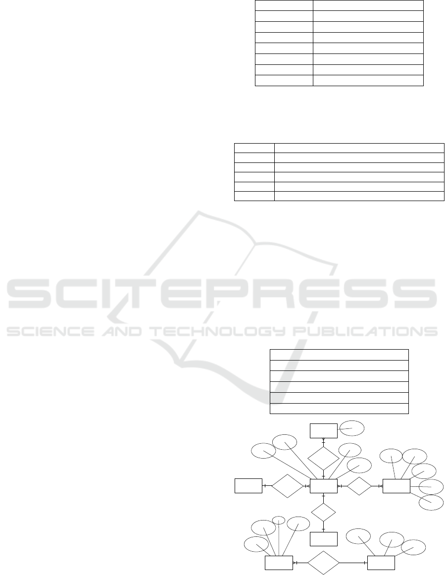
generated cardinalities. Table 3 contains relationships
between entities and cardinalities. Entity’s name
which are in the format of (Entity> cardinality) and
“*” represents the multiplicity. Fig. 5 is the ERD
extracted by this approach. The process flow in this
case is trivial, and thus omitted.
Table 3: Entities Relationships.
store>1
(
has
)
b
ranch>*
b
ranch>1
(
mana
g
ed
)
mana
g
er>1
b
ranch>1
(
sells
)
p
roduct>*
p
roduct>* (sold)
b
ranch>1
b
ranch>1 (employs) worker>*
labour>1
(p
rocess
)
sale>*
Store
Branch
Manager
Product
Worker
LabourSale
Has
managed
sells
employs
process
code
name
size
unit_cost
shelf_no
Branch_
Number
Name
address
Phone_
Number
Sale_
Number
date
time
total_
Amount
Name
address
Phone_
Number
ID
Figure 5: ERD generated from requirements in case study
1.
ENASE 2018 - 13th International Conference on Evaluation of Novel Approaches to Software Engineering
198
3.2 Case Studies of Processing Use
Case Specification
UCS of “Capture witness Report” from Car Crisis
management system. Due to the limitation of space,
we are not considering all section by (Kienzle et.al,
2010).
Main Success Scenario.
1. Coordinator provides witness information (first name, last
name, phone number, and address) to System as reported by the
witness.
2. Coordinator informs System of location and type of crisis as
reported by the witness.
2a.1 System contacts PhoneCompany to verify witness information.
2a.2 PhoneCompany sends address and phone information to
System.
2a.3 System validates information received from the
PhoneCompany.
3. System provides Coordinator with a crisis-focused checklist.
4. Coordinator provides crisis information (crisis details, time
witnessed) to System as reported by the witness.
5. System assigns an initial emergency level to the crisis and sets
the crisis status to active.
Use case ends in success.
Alternate.
1a. The call is disconnected. The base use case terminates.
2a. The call is disconnected. The base use case terminates.
3a.1 System request video feed from Surveillance System.
3a.2 Surveillance System starts sending video feed to System.
3a.3 System starts displaying video feed for Coordinator.
4a The call is disconnected.
4a.1 Use case continues at step 5 without crisis information.
5a. PhoneCompany information does not match information
received from Witness.
5a.1 The base use case is terminated.”
Firstly, sentences from the alternate section are
aligned with the relevant sentences of the main flow
section. For instance, the first sentence in the alternate
flow (i.e. ‘1a’) will be joined with the sentence
numbered 1 of the main section, so we are
understanding all the branching processes. After the
sequencing of sentences, POS-tagging, and TDRs
(appendix A.1) are applied to extract entities with
frequency (in Table 4) and attributes (in Table 5) in
the first two-way iteration.
Table 4: Entities.
Entities Frequency
(w.r.t TDs)
Coordinato
r
6
Witness 6
Crisis 6
Phonecompan
y
3
Checklist 1
Surveillance 1
video fee
d
1
Emer
g
enc
y
1
camera vision 2
Situation 1
Table 5: Attributes.
Entities Attributes
witness firs
t
name , las
t
name , phone numbe
r
, address
Crisis location, type , crisis detail , time , crisis status
Phonecompany address
Emergency emergency level
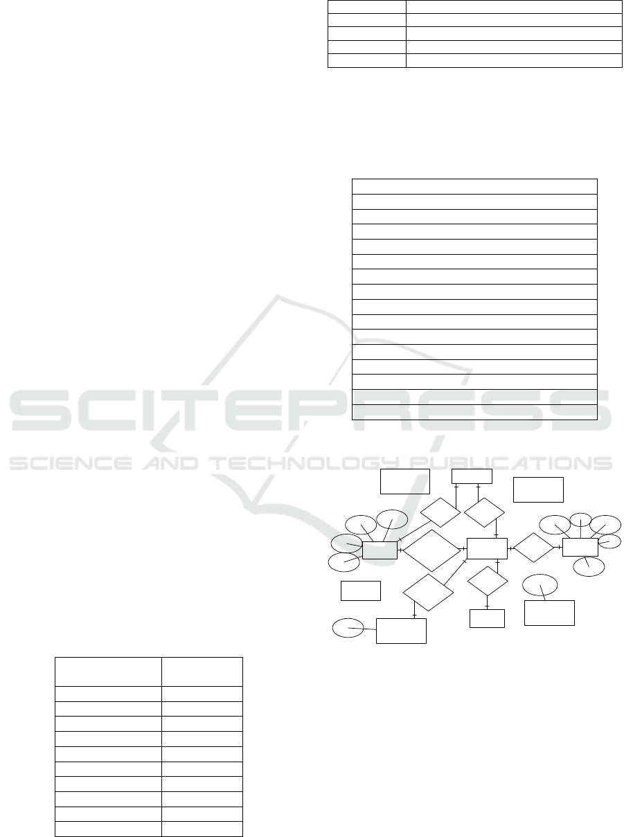
After applying TDRs (appendices A.2 & A.3), the
relationships and cardinalities generated in second
and third iterations of TDs processing displayed in
table 6.
Table 6: Entities Relationships.
COORDINATOR>1
(
REPORTED
)
WITNESS>1
coordinator>1 (has) crisis>1
coordinator>1 (verify)
p
honecompany>1
coordinator>1 (confirm) situation>1
witness>1
(
informs
)
coordinator>1
witness>1
(p
rovides
)
checklist>1
p
honecom
p
an
y
>1
(p
rovides
)
coordinator>1
p
honecompany>1 (sends) coordinator>1
p
honecompany>1 (received) coordinator>1
checklist>1 (reported) witness>1
crisis>1
(
assi
g
ns
)
coordinator>1
witness>1
(
received
)
coordinator>1
coordinator>1 (confirm) witness>1
witness>1 (describes) coordinator>1
coordinator>1 (determines) witness>1
witness>1
(
callin
g)
coordinator>1
Using the generated results, a corresponding
ERD is depicted in Figure 6.
witness
coordinator
Phonecompany
crisis
Check List
reported,
inform, describe,
dtermines,
calling
has, confirm
provide,
first
name
location
address
Surveillance
Video feed
emergency
camera vision
situation
last name
phone
number
address
type
crisis
detail
time
crisis
status
emergency
level
confirm,
determines
verify, provides,
send, receive
provides,
reported
Figure 6: ERD generated from Use Case Specifications.
4 RELATED WORK
The ER model was presented by Chen in 1976, and
included 11 rules for identifying entities, attributes
and relationships (Chen, 1976). Song et.al, (1995)
presented the extended ERD by introducing new
concepts such as generalization and abstraction.
Iterative Process for Generating ER Diagram from Unrestricted Requirements
199

Various automated and semi-automated efforts
have been made to extract conceptual models from
different formats of the requirements.
Elbendak et.al, (2011) proposed a semi-automatic
tool called Class-Gen for processing the use case
description to generate object-oriented class models.
The proposed rules are based on the basic concepts of
ERD generation explained by (Chen, 1976) i.e. noun
and gerund are potential entities and verbs are
relationships. Rules to extract attributes are also
based on the previous concepts in literature.
Omer and Wilson (2015) tried to extract database
schema form user requirements using a natural
language processing tool, considering only subject
and object of the sentences.
Tjoa and Berger (1993) proposed a tool to extract
information by applying rules. Unfortunately, no tool
was developed. These rules are based on the
assumption that syntactic structure of the language
can converted into data models.
Overmyer et.al, (2001) presented a methodology
with prototype tool (Linguistic Assistant for Domain
Analysis) for Text analyzing. After speech tagging,
they tried to find multi-word phrases for extracting
entities.
Omar et.al, (2004) proposed a semi-automated
heuristic tool called ER-Converter to extract entities,
attributes and relationships. After pre-processing
using a memory-based shallow parser, heuristic
weights were assigned to potential entities. Human
involvement is required to attach attributes to entities
and to find a relationship between entities.
Meziane and Vadera (2004) presented a semi-
automated approach to generate ER models. From the
requirements, authors tried to generate logical forms
by converting sentences into determiner (Base,
Focus) format and then extract entities by processing
POS. In this approach relationship is generated using
quantifiers e.g. ‘the’, ‘a’ etc.
Harmain and Gaizauskas (2003) proposed a tool
CM-Builder to generate object-oriented framework
using NLP techniques. An initial static structure of
conceptual model generated first and then refined
manually.
Btoush and Hammad (2015) authors presented a
tool to extract ER diagram. After POS-tagging, words
are connected as chunks and then apply rules (based
on basic concepts e.g. nouns are potential entities) to
extract entities, attributes and relationships. This tool
can only process simple sentences.
Lilac (2009) presented an approach for designing a
database from requirements. They applied syntactic
analysis by using context-free grammar rules to
collect a word from sentences and the semantic
analysis to separate entities and attributes from the
list.
Sagar and Abirami (2014) presented a tool to
create a conceptual model from functional
requirements using TDs. They defined TDs based
rules to extract entities, attributes, relationships and
operations.
Yue et.al, (2015) proposed an automated approach
to extract analysis models from UCS using parse tree
and POS tags generated by NL parser. In this
approach, five basic sentence structures are used to
extract class diagram. In their previous effort Yue
et.al, (2010) used aToucan tool to extract activity
diagram from UCS by tracing links between
activities.
Ambriola and Gervasi (2006) presented a software
called CIRCE to convert natural language
requirements to models. The authors tried to extract
static models such as Entity-Relationship or UML
class diagrams, and dynamic models such as finite
state automata or event-condition-action rules. Parse
trees obtained from requirements converted to tuples
and then enhanced using extensional knowledge
about the basic structure of software.
Bajwa et.al, (2009) proposed a tool to generate
UML class diagram with attributes and operations
from natural language requirements. After POS
tagging, words are separated based on tags. Class
objects and attributes extracted from noun sets to
generate the class diagram.
Abdessalem et.al, (2016) presented an approach to
generate a class diagram using pattern rules in the
form of regular expressions. After pre-processing,
sentences are matched to these patterns to obtain
classes and attributes. Associations between classes
are generated from dependencies.
Thakur and Gupta (2017) presented an automated
approach to extract class diagram from use cases.
After generating dependencies of each sentence, they
applied transformation rules on TD to extract entities,
attributes and operations.
Lucassen et.al, (2017) effort authors developed a
tool, called Visual Narrator. This tool extracts the
conceptual model from user stories. This tool only
processes specifically formatted user stories. Each
sentence in the user story is divided into three parts:
role, means, and ends. They used the GRIM method
combining with NLP tool to process user stories. In
this approach, for POS tagging dependency
generating, SpaCy is used. While extracting classes,
a weight is assigned to the potential candidate and
final selection of the classes is based on the weight.
Arora et.at (2016) proposed an automated method
to extract domain model from unrestricted general
ENASE 2018 - 13th International Conference on Evaluation of Novel Approaches to Software Engineering
200
requirements and represented in the form of classes.
After preprocessing, nouns and verbs separated. TDs
generated from the parse tree. Three rules applied to
TDs to extract concepts, attributes and relationships.
Table 7: Type Dependencies use by Authors to extract
Entities and Attributes.
Processed by Dependency
Lucassen et.al,
(2017)
nsubj (A, B), dobj(A,B),
pobj(A,B), nn(A,B), amod(A,B)
Thakur and Gupta
(2017)
nsubj (A, B), nsubjpass(A,B),
dobj(A,B), pobj(A,B), nn(A,B),
amod(A,B), xcomp(A,B),
prep(A,“in”), prep(A,“of”),
poss(A, B), aux(A,B),
num
(
A,B
)
Arora et.al,
(2016)
nsubj (A, B), dobj(A,B),
amod(A,B), ref_to(A,B),
rcmod(A,B), ccomp(A,B) ,
vmod(A,B).
Abdessalem et.al
(2016)
nsubj (A, B), nsubjpass(A,B),
dobj(A,B)
Sagar and
Abirami (2014)
nsubj (A, B), dobj(A,B)
Table 7 contains the TDs used by the authors to
generate the artifacts of the conceptual models. They
only used a subset of the TDs we have used in our
approach. For example, we also consider the
compound with nsubj or dobj.
The approaches discussed above take input
requirements in a restricted format. Arora et.at (2016)
tried to process unrestricted general requirements.
Our approach can handle requirements in both
restricted and unrestricted format.
Studies on the existing rules-based techniques for
domain model extraction showed that the results are
unsatisfactory (Echeverría et.al, 2017).
5 PERFORMANCE
EVALUATION
To compare and validate the results of our ERD
generation approach, we developed an application
and tested it on various types of requirements
specifications including general requirements, User
Stories and UCSs that appeared in the literature. For
performance evaluation, we used the same
performance metrics as used by the researchers, recall
and precision and over-generation. Details are
presented by (Echeverría et.al, 2017) and
(Abdessalem et.al, 2016).
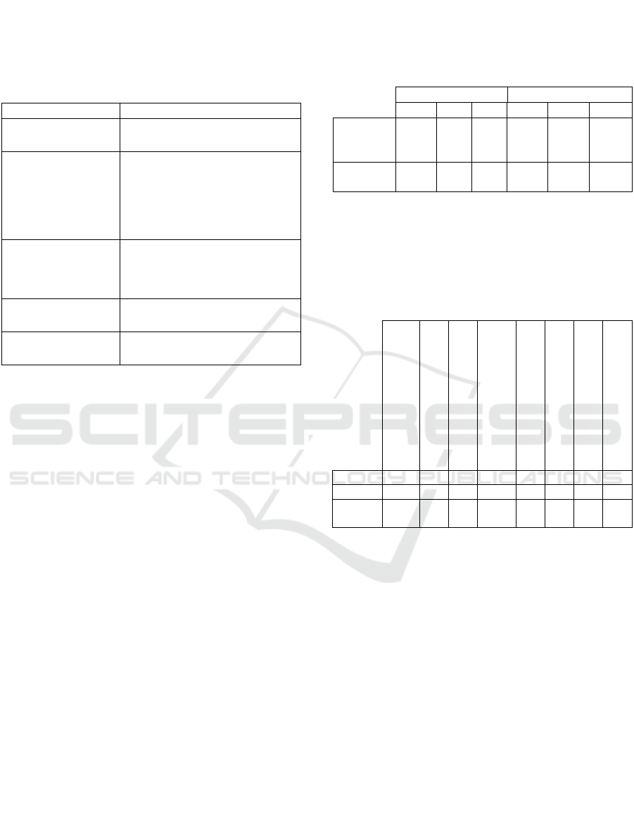
Table 8 contains the comparison with the tool
proposed by Lucassen et.al, (2017), considering the
similar user stories (i.e. ArchivesSpace).
Table 8: Comparison of Performance Metrics based on User
Stories of Archivespace.
Entities Relationships
TP FP FN TP FP FN
Lucassen
et.al,
(2017)
89.5% 3.9% 6.5% 74.4% 10.9% 14.7%
Our
approach
92.3% 3.7% 4% 76.6% 13 % 12%
Listed below in Table 9 are the comparisons with
the automated tool by Abdessalem et.al, (2016). We
have used the same requirements document (i.e.
Library system).
Table 9: Comparison of Performance Metrics based on the
Requirements of Library System.
Harmain and Gaizauskas,
2003
Lavoie and Rambow,
2001
Herchi and Abdessalem ,
2012
Abdessalem et.al (2016)
Bajwa et.al, 2009
Sagar and Abirami, 2014
Omer and Wilson, 2015
Our Approach
Recall 73% 62% 52% 89% 56% 72% 75% 95%
Precision 66% 70% 75% 92.3% 65% 65% 60% 93%
Over
Genratio
n
62% 70% 75% 26% 75% 68% 50% 9 %
We compared the results of use cases with the
closely related techniques proposed by (Thakur and
Gupta 2017) and (Yue et.al, 2016) and found
improved results with our proposed technique. For
instance, by considering the ATM withdrawal use
case specification (common case study of both
techniques), the correctness of (Thakur and Gupta
2017) and (Yue et.al, 2016) is 65% and 95%
respectively. While the accuracy of our technique for
the use case is 96%.
6 CONCLUSION AND FUTURE
WORK
In this paper, we proposed an automated iterative
approach to extract the components of ERD from
unrestricted requirements. We have developed a tool
using Stanford CoreNLP 3.8 APIs for the pre-
Iterative Process for Generating ER Diagram from Unrestricted Requirements
201

processing of requirements documents. Furthermore,
we defined new TDs base rules to generate the
required conceptual model. The key advantages of the
proposed technique are;
Processing of unrestricted formats of
requirement documents, including general
requirements, UCSs and User Stories.
Refined TDs for entity relationship model
extraction.
Correlation of pronouns with nouns to extract
entity.
Extending the basic relationship extraction that
is typically restricted in a single sentence, we
also extracted entity relationships by examining
the data flow in multiple consecutive sentences.
Cardinalities extraction with and without
specific indicators.
In future, our aim is to enhance the technique by
applying domain knowledge. Domain knowledge not
only helps to differentiate between True and false
artifacts of ERD but also helps in generalization and
aggregation of artifacts.
REFERENCES
Al-Safadi, L.A., 2009. Natural Language Processing for
Conceptual Modeling. JDCTA, 3(3), pp.47-59.
Ambriola, V. and Gervasi, V., 2006. On the systematic
analysis of natural language requirements with c irce.
Automated Software Engineering, 13(1), pp.107-167.
Arora, C., Sabetzadeh, M., Briand, L. and Zimmer, F.,
2016, October. Extracting domain models from natural-
language requirements: approach and industrial
evaluation. In Proceedings of the ACM/IEEE 19th
International Conference on Model Driven
Engineering Languages and Systems (pp. 250-260).
ACM.
Bajwa, I.S., Samad, A. and Mumtaz, S., 2009. Object
oriented software modeling using NLP based
knowledge extraction. European Journal of Scientific
Research, 35(01), pp.22-33.
Btoush, E.S. and Hammad, M.M., 2015. Generating ER
diagrams from requirement specifications based on
natural language processing. International Journal of
Database Theory and Application, 8(2), pp.61-70.
Ben Abdessalem Karaa, W., Ben Azzouz, Z., Singh, A.,
Dey, N., S Ashour, A. and Ben Ghazala, H., 2016.
Automatic builder of class diagram (ABCD): an
application of UML generation from functional
requirements. Software: Practice and Experience,
46(11), pp.1443-1458.
Chen, P.P.S., 1976. The entity-relationship model—toward
a unified view of data. ACM Transactions on Database
Systems (TODS), 1(1), pp.9-36.
De Marneffe, M.C. and Manning, C.D., 2008. Stanford
typed dependencies manual (pp. 338-345). Technical
report, Stanford University.
Elbendak, M., Vickers, P. and Rossiter, N., 2011. Parsed
use case descriptions as a basis for object-oriented class
model generation. Journal of Systems and Software,
84(7), pp.1209-1223.
Echeverría, J., Pérez, F., Pastor, Ó. and Cetina, C., 2017.
Assessing the Performance of Automated Model
Extraction Rules. 26th International conference on
Information Systems Development.
Harmain, H.M. and Gaizauskas, R., 2003. Cm-builder: A
natural language-based case tool for object-oriented
analysis. Automated Software Engineering, 10(2),
pp.157-181.
Hogenboom, F., Frasincar, F. and Kaymak, U., 2010. An
overview of approaches to extract information from
natural language corpora. Information Foraging Lab,
p.69.
Herchi, H. and Abdessalem, W.B.,July, 2012. From user
requirements to UML class diagram. International
Conference on Computer Related Knowledge (ICCRK’
2012), Sousse, Tunisia.
Kienzle, J., Guelfi, N. and Mustafiz, S., 2010. Crisis
management systems: a case study for aspect-oriented
modeling. Transactions on aspect-oriented software
development VII, pp.1-22.
Lavoie, S.P. and Rambow, B., 2001. Conceptual modeling
through linguistic analysis using LIDA. In Proceedings
of the 23rd International Conference on Software
Engineering, ICSE 2001.
Larman, C. and Applying, U.M.L., 2004. Patterns: An
Introduction to Object-Oriented Analysis and Design
and Iterative Development.
Lucassen, G., Robeer, M., Dalpiaz, F., van der Werf, J.M.E.
and Brinkkemper, S., 2017. Extracting conceptual
models from user stories with Visual Narrator.
Requirements Engineering, pp.1-20.
Meziane, F. and Vadera, S., 2004. Obtaining ER diagrams
semi-automatically from natural language
specifications.
Neill, C.J. and Laplante, P.A., 2003. Requirements
engineering: the state of the practice. IEEE software,
20(6), pp.40-45.
Omar, N., Hanna, J.R.P. and McKevitt, P., 2004. Heuristic-
based entity-relationship modelling through natural
language processing. In Artificial Intelligence and
Cognitive Science Conference (AICS) (pp. 302-313).
Artificial Intelligence Association of Ireland (AIAI).
Omer, M. and Wilson, D., 2015. Implementing a Database
from a Requirement Specification. World Academy of
Science, Engineering and Technology, International
Journal of Computer, Electrical, Automation, Control
and Information Engineering, 9(1), pp.33-41.
Song, I.Y., Evans, M. and Park, E.K., 1995. A comparative
analysis of entity-relationship diagrams. Journal of
Computer and Software Engineering, 3(4), pp.427-459.
Siqueira, F.L. and Silva, P.S.M., 2011, April. An Essential
Textual Use Case Meta-model Based on an Analysis of
Existing Proposals. In WER.
ENASE 2018 - 13th International Conference on Evaluation of Novel Approaches to Software Engineering
202

Sagar, V.B.R.V. and Abirami, S., 2014. Conceptual
modeling of natural language functional requirements.
Journal of Systems and Software, 88, pp.25-41.
Schneider, K., 2009. Experience and knowledge
management in software engineering. Springer Science
& Business Media.
Tjoa, A.M. and Berger, L., 1993, December.
Transformation of requirement specifications
expressed in natural language into an EER model. In
International Conference on Conceptual Modeling (pp.
206-217). Springer, Berlin, Heidelberg.
Thakur, J.S. and Gupta, A., 2017. Automatic generation of
analysis class diagrams from use case specifications.
arXiv preprint arXiv:1708.01796.
Uduwela, W.C. and Wijayarathna, G., 2015. An Approach
To Automate The Relational Database Design Process,
Int. J. Database Manag. Syst. ( IJDMS ), vol. 7, no. 6,
pp. 49–56
Yue, T., Briand, L.C. and Labiche, Y., 2010, June. An
Automated Approach to Transform Use Cases into
Activity Diagrams. In ECMFA (pp. 337-353).
Yue, T., Briand, L.C. and Labiche, Y., 2015. aToucan: an
automated framework to derive UML analysis models
from use case models. ACM Transactions on Software
Engineering and Methodology (TOSEM), 24(3), p.13.
APPENDIX
Type Dependencies based Rules (TDRs) to extract
entities, attributes relationships and cardinalities.
TDR1.
if Dependency= nsubj(A, B) OR nsubjpass(A,
B)
if A=VB|VBN and B=Noun and B≠Basic_Attrib
then
If prevTD = “compound” then
Entity.add(compound(B) + Compound(A))
else Entity.add(nsubj(B))
TDR2.
if Dependency= (nsubj(A, B) OR nsubjpass(A,
B))
if A=VB|VBN and B=Noun and B =
Basic_Attrib then
if prevTD = “compound” then
Attributes.add(compound(B) +
Compound(A))
else Attributes.add(nsubj(B))
TDR3.
if Dependencies=dobj(A,B), iobj(A,B) OR
pobj(A,B)
if A=VB and B=Noun and B≠Basic_Attrib and
prevTD≠”amod” and prevTD≠”advmod” and VB≠
”entered” | “inputted” | “saved” |”added”
| “has” then
if prevTD = “compound” then
Entity.add(compound(B) + Compound(A))
else Entity.add(dobj(B))
TDR4.
if Dependencies=dobj(A,B), iobj(A,B) OR
pobj(A,B)
if A=VB and B=Noun and (B = Basic_Attrib
OR VB =”entered” | “inputted” | “saved”
|”added” | “has”) then
if prevTD = “compound” then
Attributes.add(compound(B) +
Compound(A))
else Attributes.add(dobj(B))
TDR5.
if Dependencies= (dobj (A,B) OR iobj(A,B) OR
pobj(A,B))
if A=VB and B=Noun and (B = Basic_Attrib OR
VB =”entered” | “inputted” | “saved”
|”added” | “has”) then
if (prevTD = “amod” || prevTD = “advmod”)
and prev(B)=”JJ” then
Attributes.add(amod(B) + amod(A))
else Attributes.add(dobj(B))
TDR6.
if Dependency = nmod:of(A,B)
if A=noun and B=Noun and A = Basic_Attrib
and B≠Basic_Attrib then
Entity.add(B)
Attributes.add(A)
if A=noun and B=Noun and A≠Basic_Attrib
and B≠Basic_Attrib then
Entity.add(A)
Entity.add(A)
if A=noun and B=Noun and A=Basic_Attrib
and B=Basic_Attrib then
Attributes.add(A + “of” + B)
TDR7.
if Dependency= nmod:in(A,B)
if A=Noun and B=Noun then
Entity.add(B)
Attributes.add(A)
TDR8:
if Dependency= nmod:to(A,B), nmod:for(A,B),
nmod:from(A,B) OR nmod:as(A,B)
if B=Noun then
Entity.add(B)
TDR9.
if Dependencies=nmod:by(A,B),
nmod:agent(A,B) OR nmod:with(A,B)
if B=Noun and B = Basic_Attrib then
Attributes.add(B)
else if B=Noun and B ≠ Basic_Attrib then
Entity.add(B)
TDR10.
if Dependencies= nmod:poss(A,B)
if A=Noun and B = Noun then
Entity.add(B)
Attributes.add(A)
else if A=Noun and B= PREP ≠ Basic_Attrib
then
Attributes.add(B)
TDR11.
if Dependencies = amod(A,B)
if A=Noun and B = JJ and A=basic_Attrib
then
Attributes.add(B + A)
else if A=Noun and B=JJ and A≠Basic_Attrib
then
Entity.add(A)
Iterative Process for Generating ER Diagram from Unrestricted Requirements
203

TDR12.
if Dependencies=compound(A,B)and
nextTD≠nsubj and nextTD≠dobj
if A=Noun and B = Noun and A=Basic_Attrib
and B≠ Basic_Attrib then
Attributes.add(B + A)
Entity.add(B)
else if A=Noun and B = Noun and
A≠Basic_Attrib and B= Basic_Attrib then
Attributes.add(A + B )
Entity.add(A)
else if A=Noun and B = Noun and
A=Basic_Attrib and B= Basic_Attrib then
Attributes.add(B+A)
else if A=Noun and B = Noun and
A≠Basic_Attrib and B≠ Basic_Attrib then
Entity.add(B+A)
EndIf
TDR13.
if Dependencies = nmod:and(A,B) OR
nmod:or(A,B)
if A=Noun and B = Noun and A=Basic_Attrib
and B= Basic_Attrib then
Attributes.add(A)
Attributes.add(B)
else if A=Noun and B = Noun and
A≠Basic_Attrib and B≠ Basic_Attrib
then
Entity.add(A)
Entity.add(B)
TDR14.
if nsubj(Verb, E
1
) & dobj(Verb, E
2
)
relationship.add( E
1
(Verb) E
2
)
TDR15.
if nsubjpass(VBN, E
1
) and (nmod:agent (VBN,
E
2
) OR nmod:by (VBN, E
2
))
relationship.add ( E
1
(VBN) E
2
)
TDR16.
if nmod:of (E
1
, E
2
)
relationship.add(E
1
(has) E
2
)
TDR17.
if nsubj(Verb, E
1
) and dobj(VBN, E
2
) and
nmod:of (E
2
, E
3
)
relationship.add (E
1
(VB) E
2
)
relationship.add ( E
2
(“has”) E
3
)
TDR18.
if nsubj(VB, E
1
) and dobj(VB,E
2
)and
nmod:to(VB,E
3
)
relationship.add (E
1
(VB) E
2
)
relationship.add (E
2
(VB+ “to”) E
3
)
relationship.add(E
1
(VB+ “to”) E
3
)
TDR19.
if nsubjpass(VBN, E
1
) and nmod:to (VBN, E
2
)
relationship.add ( E
1
(VBN + “to”) E
2
)
TDR20.
if nsubj(Verb, E
1
) and nsubjpass(VBN, E
2
) and
nmod:to (VBN, E
3
)
relationship.add (E
1
(VB) E
2
)
relationship.add,(E
1
(VBN + “to”) E
3
)
relationship.add ( E
2
(VBN + “to”)
E
3
)
TDR21.
if nsubj(VB, E
1
) and nmod:in (VB, E
2
)
relationship.add ( E
1
(VB +”in”) E
2
)
TDR22.
if nsubj(VB, E
1
) and nmod:for (VB, E
2
)
relationship.add (E
1
(VB + “for”) E
2
)
TDR23.
if nmod:as(VB, E
1
) and dobj (VB, E
2
)
relationship.add (E
1
(VB) E
2
)
TDR24.
if dependency = amod( E
1
, JJ)
cardinalities.add (E
1
“>”JJ )
TDR25.
if dependency = nummod( E
1
, CD)
cardinalities.add (E
1
“>” CD )
TDR26.
if dependency = det( E
1
, DT)
if (DT=”Each” OR ”All” OR ”some” OR ”Any”
OR “Many” OR “Every” OR “multiple”)
cardinalities.add (E
1
“>” N )
if (DT= “a” OR “an” )
cardinalities.add (E
1
“>” 1)
ENASE 2018 - 13th International Conference on Evaluation of Novel Approaches to Software Engineering
204
