Shifting Speed and Belt Behavior of Model CVT
(Continuously Variable Transmission) with Push and Pull Type
V-belt Driven on Semi-Transparent Pulleys
Influence of Stiffness of V-belt in Clamping Direction
Shinnosuke Nomura
1
, Kazuya Okubo
2
and Toru Fujii
2
1
Graduate student of Doshisha University, 1-3 Tataramiyakodani, Kyotanabe-city, 610-0394, Kyoto, Japan
2
Department of Mechanical Engineering, Doshisha University, 1-3 Tataramiyakodani, Kyotanabe-city,
610-0394, Kyoto, Japan
Keywords: CVT (Continuously Variable Transmission), V-belts, Shifting Speed, Deformation.
Abstract: The purpose of this study is to investigate influence of the stiffness of V-belt in clamping direction on
shifting speed of V-belt type CVT (Continuously Variable Transmission). Model CVT with push and pull
type V-belt was prepared with semi-transparent pulleys made of epoxy resin in order to observe the belt
behaviour in the pulley groove. The stiffness of the belt in clamping direction was changed to investigate
the influence on the shifting speed in which the cross sections of belts were reduced as the alternative types
of belts. At the case where the belt pitch radius was increased, the behaviour of elements of the push type V-
belt in the pulley groove indicated that the remarkable radial slip between the element and pulley was not
occurred. It was suggested that the pitch radius of the belt entering into pulley groove was depended on the
deformation of the belt in compression in clamping direction in pulley groove. It was shown that the shifting
speed was increased by reducing the stiffness of belts in clamping direction regardless of the belt type.
1 INTRODUCTION
The market share of vehicles with V-belt type CVT
is expected to keep growing in the future because
they achieve a higher fuel economy than vehicles
with other transmissions (T.Fujii, 2008). CVTs have
advantages capable of maintaining proper rotational
speed at all time in terms of engine efficiency by
changing speed ratio flexibly and continuously.
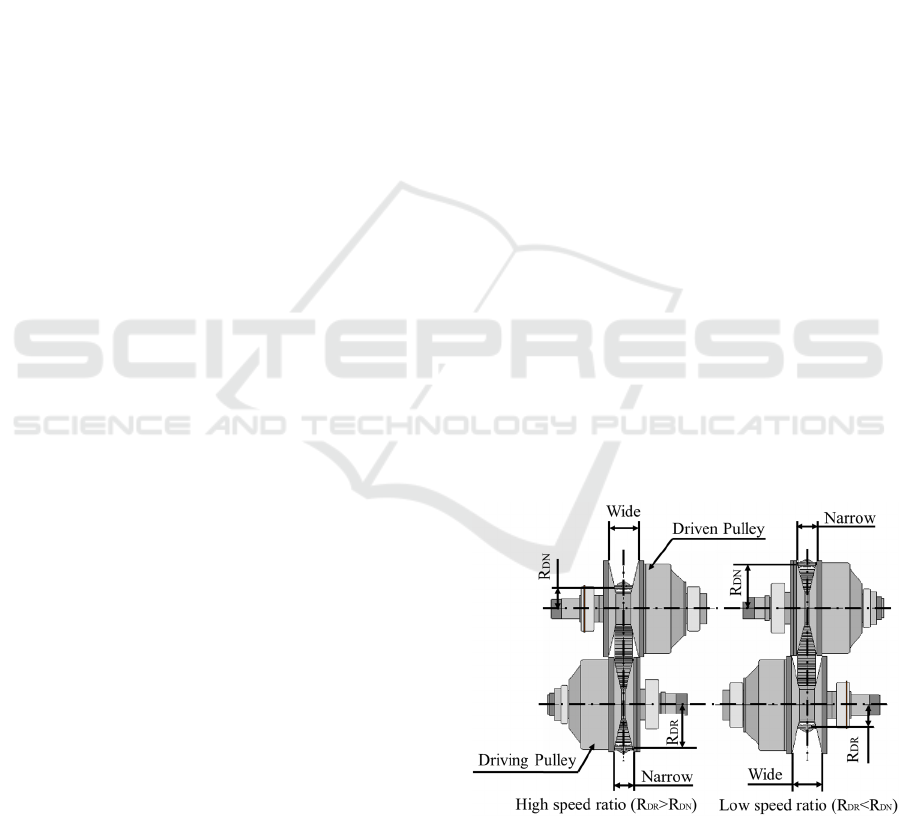
An example of V-belt type CVT setup is shown
in Figure 1. The V-belt type CVT is composed of a
driving V-pulley, a driven V-pulley and a V-belt.
These V-belts are classified into two types, push
type V-belt and pull type V-belt. The driving V-
pulley and the driven V-pulley both are usually
composed of a movable pulley and a fixed pulley.
The V-belts are clamped between the movable
pulley and the fixed pulley in order to generate
traction by frictional force. Clamping force is
usually applied onto belt by oil pressure generated
by oil pump and others. On changing balance of
clamping forces between the driving movable
V-pulley and the driven movable V-pulley, the shift
change sets in.
Figure 1: V-belt type CVT setup.
To keep safety operation and provide practical
shifting speed clamping force is often excessive over
the reasonable force. Oil pump loss for applying
clamping force onto belt often accounts for approxi-
474
Nomura, S., Okubo, K. and Fujii, T.
Shifting Speed and Belt Behavior of Model CVT (Continuously Variable Transmission) with Push and Pull Type V-belt Driven on Semi-Transparent Pulleys.
DOI: 10.5220/0006781604740480
In Proceedings of the 4th International Conference on Vehicle Technology and Intelligent Transport Systems (VEHITS 2018), pages 474-480
ISBN: 978-989-758-293-6
Copyright
c
2019 by SCITEPRESS – Science and Technology Publications, Lda. All rights reserved
mately 60% of loss in the whole CVT units. Therefore,
the clamping force should be reduced to increase
efficiencies of CVTs. The motivation of the work is to
develop new CVT with high efficiencies and response.
The purpose of this study is to investigate the
influence of stiffness of V-belt in clamping direction
on shifting speed of V-belt type CVT in order to
discuss the mechanical design to determine
appropriate clamping force.
2 TEST METHOD
2.1 Test Setup
The model CVT was developed with light V-belt
and semi-transparent epoxy resin pulleys in which
the belt behaviour in pulley groove was able to be
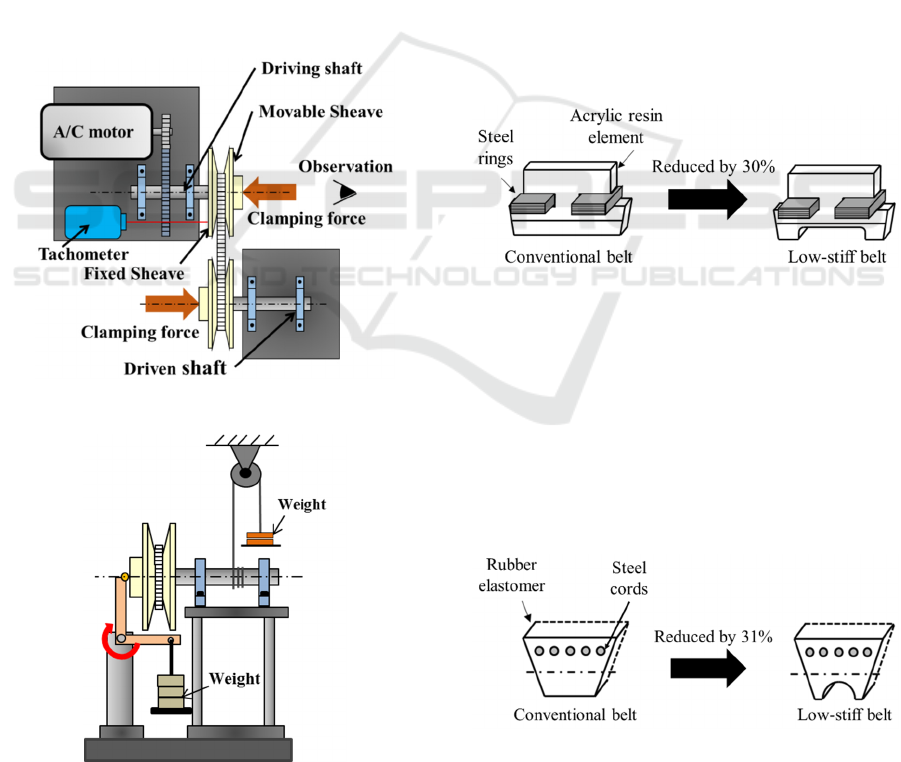
observed. Figure 2(a)(b) shows the illustration of
model CVT test apparatus used for measurements.
(a) Top view
(b) Front view around driven pulley
Figure 2: Schematic view of test apparatus of model CVT.
The test apparatus was set up with the model CVT
unit, the A/C motor, the winch, and the lever. The
A/C motor was installed instead of a combustion
engine to provide power. The power was transmitted
to the driven shaft from the driving shaft through the
CVT unit. Driven torque was applied by winding up
a weight by a wire on the shaft. Pulley clamping
force was also applied onto belt by another weight
with levers instead of oil pressure.
2.2 Specimens for Measurements
Pushing type model belts were originally prepared
with tentative elements made of acrylic resin and
laminated steel rings. Low-stiff push type belts with
low-stiff elements were also prepared of which cross
sections of the elements were reduced by
introducing a flat notch to change the stiffness in
clamping direction (Figure 3). For the alternative
push type belt, stiffness of the belt was reduced
about 30% in clamping direction compared with that
of the original belt.
Figure 3: Elements of push type belts.
Pulling type model belts were also prepared
made of rubber elastomer and steel cords. Low-stiff
pull type belts were also prepared of which cross
sections of the belt were reduced by introducing a
half circular notch to change the stiffness in
clamping direction (Figure 4). For the alternative
pull type belt, stiffness of the belt was reduced about
31% in clamping direction compared with that of the
original belt.
Figure 4: Cross sections of pull type belts.
Shifting Speed and Belt Behavior of Model CVT (Continuously Variable Transmission) with Push and Pull Type V-belt Driven on
Semi-Transparent Pulleys
475
2.3 Measurement of Shifting Speed
The speed ratio i was defined as the equation (1).
DN
DR
DR
DN
N
N
R
R
i ==
(1)
where, R
DR
, R
DN
, N
DR
, N
DN
denoted the pitch radius
of belt in the driving pulley and in the driven pulley,
the rotational speed of the driving shaft and of the
driven shaft, respectively.
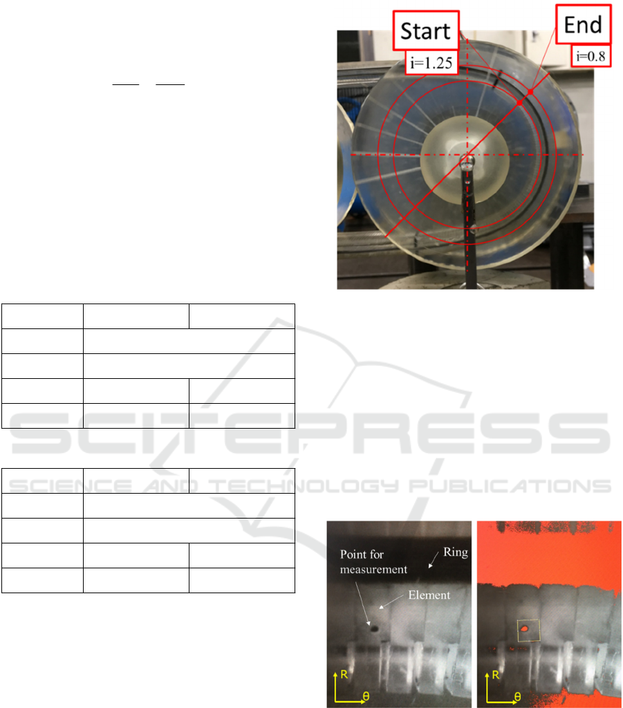
Table 1 and 2 shows test conditions for push and
pull type, respectively. The shifting speed was
defined as dR/dt (the variation of belt pith radius per
unit of time).
Table 1: Test conditions with push type belt.
Table 2: Test conditions with pull type belt.
The rotational speed of the driving pulley was about
20rpm during experiments. The transmitted torque
was also kept constant at 294Nmm. The shifting
speed was evaluated by measuring the times
required for the belt to change to change the pitch
radius associated with i=1.25 to i=0.8 for shifting up
and opposite change to shifting down, respectively
(Figure 5).
Figure 5: Measurement of shifting speed.
2.4 Measurements of Radial Slip
Figure 6 shows an example of the result of image
analysis. To evaluate radial slip between elements in
pulley groove and pulley, the behaviour of an
element of push type belt in pulley groove was
observed by a miniature camera attached onto driven
pulley. The radial displacement of the point mark
attached on contact surface of the element from
initial point was measured as radial slip between
element in pulley groove and pulley.
Figure 6: Example of result of image analysis.
3 RESULTS
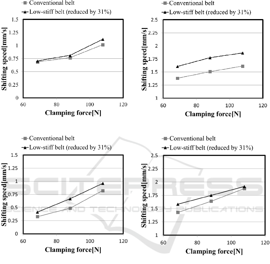
Figure 7(a)(b) and Figure 8(a)(b) show the
relationship between the shifting speed and
clamping force measured with the push type low-
stiff belt and the conventional belt. The significant
Shift up state
(
i = 1.25
→
0.8
)
Shift down state
(
i = 0.8
→
1.25
)
Rotational speed of
drivin
g
p
ulle
y
Transmitted torque
Clamping force of
drivin
g
p
ulle
y
186, 206, 225, 245, 265N 147N
Clamping force of
driven
p
ulle
y
147N 186, 206, 225, 245, 265N
20rpm
294Nmm
Shift up state
(
i = 1.25
→
0.8
)
Shift down state
(
i = 0.8
→
1.25
)
Rotational speed of
drivin
g
p
ulle
y
Transmitted torque
Clamping force of
drivin
g
p
ulle
y
186, 206, 225N 118N
Clamping force of
driven
p
ulle
y
118N 186, 206, 225N
20rpm
294Nmm
VEHITS 2018 - 4th International Conference on Vehicle Technology and Intelligent Transport Systems
476

difference was observed in the shifting speed of the
push type low-stiff belt and that of the push type
conventional belt.
These results showed that reducing the stiffness
of belt elements in clamping direction contributed to
increase the shifting speed.
(a) Under shifting up
(b) Under shifting down
Figure 7: Relationship between shifting speed and
clamping force in push type belt when transmitted torque
was almost zero.
(a) Under shifting up
(b) Under shifting down
Figure 8: Relationship between shifting speed and
clamping force in push type belt when transmitted torque
was 294[Nmm].
Figure 9(a)(b) and Figure 10(a)(b) show the
relationship between the shifting speed and
clamping force measured with the pull type low-stiff
belt and the conventional belt. The significant
difference was also observed in the shifting speed of
the pull type low-stiff belt and that of the pull type
conventional belt.
These results showed that reducing the stiffness
of belt in clamping direction contributed to
increasing the shifting speed, as well as the test
results with push type belts.
Shifting Speed and Belt Behavior of Model CVT (Continuously Variable Transmission) with Push and Pull Type V-belt Driven on
Semi-Transparent Pulleys
477
(a) Under shifting up
(b) Under shifting down
Figure 9: Relationship between shifting speed and
clamping force in pull type belt when transmitted torque
was almost zero
.
(a) Under shifting up
(b) Under shifting down
Figure 10: Relationship between shifting speed and
clamping force in pull type belt when transmitted torque
was 294[Nmm].
4 DISCUSSIONS
Figure 11 shows the radial slip between element and
pulley at the case where the belt pitch radius was
decreased and that at the case where the belt pitch
radius was increased, respectively. At the case where
the belt pitch radius was decreased, radial slip
between element and pulley was remarkably
occurred. On the other hand, at the case where the
belt pitch radius was increased, radial slip was
VEHITS 2018 - 4th International Conference on Vehicle Technology and Intelligent Transport Systems
478

almost not observed even if shifting state. It was
suggested that the belt pitch radius was increased not
by slipping between element and pulley but by
deformations of elements in clamping direction.
Figure 11: Radial slips between element and pulley for
push type belt.
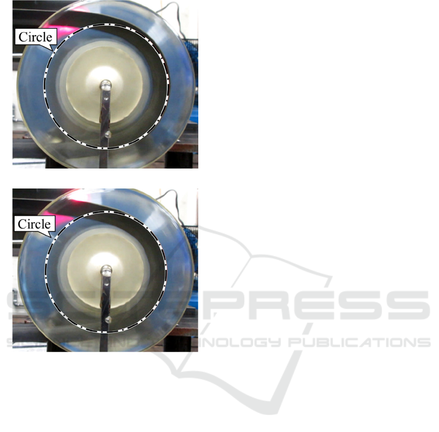
Figure 12(a)(b) and Figure 13(a)(b) show the
behaviour of push type belt and pull type belt in
pulley groove at the case where the belt pitch radius
was increased and that at the case where the belt
pitch radius was decreased. Same tendencies were
observed on the belt behaviours for push type and
pull type belt, as bellow. The belt pitch radius was
decreased maintaining complete circle shape by
which the belt significantly slipped in pulley groove
in the same time (Figure 12(b) and 13(b)). On the
other hand, the belt pitch radius was increased as
spiral shape by some deformations of the belt in
clamping direction in the pulley groove without
significant slip (Figure 12(a) and 13(a)).
The belt was deformed in compression in pulley
groove by clamping force. At the case where the belt
pitch radius was increased, the belt entering into
pulley groove should be entered at external position
in radial direction because internal sheer force was
produced by the difference of the radial locations
around the entrance. The difference of the radial
locations was increased when large deformation of
the belt was occurred with low-stiff belt in clamping
direction. Therefore, the pitch radius of the belt
entering into pulley groove was depended on the
deformation of the belt in pulley groove.
That is reason why reducing the stiffness of belt
in clamping direction contributed to increase the
shifting speed. This study showed that the shifting
speed of CVT was improved when the stiffness of
belt was reduced in clamping direction regardless of
the belt type.
(a) In case of increasing of belt pitch radius
(b) In case of decreasing of belt pitch radius
Figure 12: Behaviours of push type belt in pulley groove
.
Shifting Speed and Belt Behavior of Model CVT (Continuously Variable Transmission) with Push and Pull Type V-belt Driven on
Semi-Transparent Pulleys
479
(a) In case of increasing of belt pitch radius
(b) In case of decreasing of belt pitch radius
Figure 13: Behaviours of pull type belt in pulley groove.
5 FUTURE WORK
We are expecting these results should be applied to
actual CVT with the metal V-belt and pulleys. To do
this, we will evaluate appropriate dimensions such
as the shape and material of belt.
6 CONCLUSIONS
This study investigated influence of the stiffness of
V-belt in clamping direction on shifting speed of V-
belt type CVT by observing the belt behaviour in
pulley groove with semi-transparent pulleys. These
conclusions were obtained as follow.
(1) At the case where the belt pitch radius was
increased, the behaviour of belt elements in the
pulley groove indicated that the remarkable
radial slip between belt element and pulley was
not occurred.
(2) The pitch radius of the belt entering into pulley
groove was depended on the deformation of the
belt in compression in clamping direction in
pulley groove.
(3) The shifting speed of CVT was improved when
the stiffness of belt was reduced in clamping
direction regardless of the belt type.
REFERENCES
T. Fujii, K. Ookubo, Power Loss in CVT using Metal
V-belt, Journal of Society of Automotive Engineers of
Japan, Vol.62, No.3, 2008, p.58-65.
Yoshioka, Drivetrain, Journal of Society of Automotive
Engineers of Japan, Vol.66, No.8, 2012, p.110-113.
T. Kanda, H. Totsuka, M. Oonuma, N. Shudo, T. Hirata,
U. Ogata, Development of New CVT for Global
Compact Car, Honda R&D Technical Review, Vol. 26,
No.26, April 2014, p40-45.
T. Kawabe, Overview of Automotive Control in the Last
Three Decades, Journal of the Society of Instrument
and Control Engineers, Vol.45, No.3, 2006, p.161-
166.
Y. Daisyou,Recent Trends and Future Perspectives on
High Efficiency Automotive Powertrain Technologies,
Journal of Society of Automotive Engineers of Japan,
Vol.69, No.9, 2015, p.10-17.
S. Hikage, T. Hibi, K. Abo, Transmission Environment
and CVT Technology, Journal of Society of
Automotive Engineers of Japan Vol.58, No.1, 2004,
p.63-68.
M. Yamanaka, Technologies and aspects for Smooth
Cruising, Journal of Society of Automotive Engineers
of Japan, Vol.61, No.12, 2007, p.4-8.
A. Aoyama, H. Sioiri, H. Akazawa, K. Suzuki,
K. Kurokawa, O. Ogi, Future Trends and Outlook
for Drive Train, Transmission Environment and CVT
Technology, Journal of Society of Automotive
Engineers of Japan, Vol.65, No.9, 2011, p.11-16.
Y. Asakura, Comments and Expectations for the Govern-
ment Programs on Automated Driving Systems,
Journal of Society of Automotive Engineers of Japan,
Vol.68, No.12, 2014, p.6-11.
T. Uchimura, Automated Vehicle Implementation Effort
in Europe and US, Journal of Society of Automotive
Engineers of Japan, Vol.69, No.12, 2015, p.22-27.
S. Morishita, H. Watanabe, Approach to Automated
Driving System in Japan, Journal of Society of
Automotive Engineers of Japan, Vol.69, No.12, 2015,
p.46-49.
VEHITS 2018 - 4th International Conference on Vehicle Technology and Intelligent Transport Systems
480
