
Pedagogical Benefits from an Exercise in Reverse Engineering for an
Aviation Software Systems
Emanuel S. Grant and Pann Ajjimaporn
Department of Computer Science, University of North Dakota, Grand Forks, U.S.A.
Keywords: Software Engineering, Reverse Engineering, Modelling Notation, UML, Activity Diagram, Sa fety-Critical
Systems, Pedagogy, Curriculum.
Abstract: Since the Y2K crisis, reverse engineering has become a major area of work in industrial software application
development, but lacks emphasis in US academia. This issue is exemplified by the high demand for software
systems in new and expanding software application areas, which has resulted in systems being implemented
before the requirements and design phases have been completed. Towards the main tenance of such systems,
it is necessary to conducted reverse engineering for the derivation of software documentation for requirements
and high-level and low-level design. When this scenario exists in the domain of safety-critical system,
particularly in the aviation industry, reverse engineering takes on greater value because such software systems
have to undergo development regulations and certification restrictions. This work reports on the pedagogical
revelations gained from conducting reverse engineering on a software system that was developed and
deployed for use in managing the assignment of commercial aircrafts to airport terminal gates. The software
system incorporated genetic algorithms solutions and was implemented on a high-speed multi-processor
system. The reverse engineering methodology applied was based on the RTCA DO-178C Software
Considerations in Airborne Systems and Equipment Certification specification for onboard avionic software
systems.
1 INTRODUCTION
In the last decades, there have been intense research
activities in software development methodologies
and modelling notations that have produced several
notable ones, namely model-driven, component-
based, and agile methodologies, along with
Coad/Yourdon (Coad, 1991), Shlaer/Mellor (Shlaer,
1988), and Unified Modelling Language (UML)
(Glass, 1997) modelling notations. With each new
methodology and modelling notation the goal has
been an attempt to address the “software crisis” that
was first identified in the late 1950s Booch, 1997).
The software crisis is best defined as the inability of
developers to deliver reliable software systems in a
timely and cost-effective manner. This crisis is
greater today than it has ever been, because of the
increasing complexity and applications of software
systems in many aspects of todays’ business and
personal endeavours.
The early proliferation of software development
methodologies and notations did not resolve the
situation, but exasperated it. Inter-project ventures
were stymied by a project developers’ unfamiliarity
with the methodology and notation of another project.
The problems arising from this over-growth of
methodologies and notations were arrested with the
merger of multiple modelling notations in a single
representation the UML (Shlaer, 1988) and the
methodologies coalescing around the Unified Process
(Kruchten, 2003) methodology. The evolution and
amalgamation of methodologies and notations, over
the early 15 years are captured in Fig. 1, which was
produced by Guido Zockoll, Axel Scheithauer &
Marcel Douwe Dekker. It should be noted that as of
this date (first quarter 2018) the UML is at version
2.5, sysML is at version 1.5, BPMN is at version
2.0.2, and xUML is at version 1.1. These modelling
notations have been developed by the Object
Management Group (OMG) and the latest versions
are not necessarily the ISO adapted version of the
modelling notations.
Notwithstanding the availability of a de facto
industry standard software modeling notation in the
UML and accompanying methodologies such as the
Rational
Process, the software crisis is still an ev
Grant, E. and Ajjimaporn, P.
Pedagogical Benefits from an Exercise in Reverse Engineering for an Aviation Software Systems.
DOI: 10.5220/0006807401790188
In Proceedings of the 10th International Conference on Computer Supported Education (CSEDU 2018), pages 179-188
ISBN: 978-989-758-291-2
Copyright
c
2019 by SCITEPRESS – Science and Technology Publications, Lda. All rights reserved
179
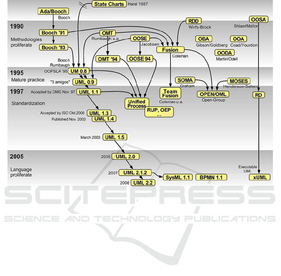
Figure 1: Evolution of object-oriented methods and notations 1980s – mid 2000s.
present phenomena of the software development
industry. In the domain of safety-critical systems, the
need to deliver correct and reliable software systems
is at the highest priority. A daunting feature of safety-
critical systems is the high degree of complexity in
the design and implementation of such systems.
Safety-critical software systems are characterized by
the resulting loss or harm to life, if such systems fail
during operation. Correspondingly, there is the
associated domain of mission-critical software
systems, wherein failure of those systems may result
in significant damage to property and equipment.
Examples of some of these safety-critical software
systems’ failure are the THERAC-25 (Leveson,
1993), the French Arian-5 rocket inaugural launch
(Lions, 1996), and Air France flight 447 (AF447) of
June 1, 2009 (Bureau, 2012). These failures
overshadow the many successful applications of
software systems in safety-critical environments,
because of the high cost in property (Ariane-5
development cost US$7 billion, payload US$500
million), and lives (Air France 447, 216 passengers
and 12 crewmembers).
Standards and methodologies play important roles
in the development of safety-critical systems. Within
the domain of avionic software systems, the RTCA
organization has developed a standard, the DO-178C
- Software Considerations in Airborne Systems and
Equipment Certification (RTCA, 2011) for USA
software development. A corresponding European
EUROCAE ED-12C Software Considerations in
Airborne Systems and Equipment Certification exist
for avionic software development in the European
territories. These documents set out a series of
objectivities, activities, and data items that are
required for the certification of on-board avionic
systems. DO-178C is a revised standard of its
previous version DO-178B, issued in late 2011 to
incorporate new guidance regarding the use of object-
oriented software development and the use of formal
specification techniques in software development.
The sole purpose of DO-178C is “for the production
of software for airborne systems and equipment that
performs its intended function with a level of
confidence in safety that complies with airworthiness
requirements” (RTCA, 2011). In order for a software
system to be use onboard aircrafts in the USA, it has
to be certified by the USA Federal Aviation
Administration (FAA). The aviation software system
must adhere to the DO-178C Specification and its
supplemental specifications.
CSEDU 2018 - 10th International Conference on Computer Supported Education
180

In the USA, any of the software development
methodologies, notations, and standards use in the
industrial arena have come into use with relative
independence of the curricula of tertiary software
engineering programs. This situation results in a
disconnect between the pedagogy of the classroom
and the practices of the workplace. In the
circumstance where there is collaboration on a
software development project between academia and
industrial partners there arise opportunities for
academia to learn some of the concrete practices of
the industry and then evolve the curricula to be more
responsive to the desired skill-set of such program
graduates. This report documents one such
experience in the development of a software system
to manage the assignment of commercial aircrafts to
airport terminal gates with multiple and conflicting
gate-assignment restrictions. The following sections
of the manuscript documents the problem definition,
in terms of the scope, deliverables, methodology, and
pedagogy. The next section documents the
experience of the project, followed by a discussion of
the educational benefits derived from the project. The
final section presents a summary in the form of a
conclusion and a look at future work in this area.
2 BACKGROUND
2.1
Problem Definition
A commercial airline company, as a part of its
operation review, identified a problem in its
information system structure. The company
encountered what was identified as a “single-point of
failure” in the process for dynamic assignment of
aircrafts to airport terminal gates. That single point
of failure in the process was the reliance on a single
specific operator to conduct dynamic assignment of
aircrafts to terminal gates. The process involves the
listing of all aircrafts for assignment and the available
gates. Aircrafts are classified based on certain
attributes, such as size, capacity, manufacturer,
arrival time, departure time, etc. Gates are classified
based on certain attributes, such as, location to
runway, fuel-port, accessibility, availability time, etc.
Other constraints pertain to global considerations,
such as available runway, taxiway path to runway,
established departure timeframes, etc.
The operator would compile the aircraft and gate
lists and generate a standard assignment, based on the
previous assignment cycle. The existing software
system would then identify any assignment conflicts,
which may arise from gate closures, incompatible
aircraft-gate assignment, aircraft late or none arrival,
etc. The operator would then attempt to resolve the
assignment conflicts by reassigning aircrafts based on
prior experience of executing this process. Whenever
that operator is unavailable, the new operator would
conduct the same operation, but the resolution would
again be based on his experience.
The company recognized the failure that may
arise if this system and process were not improved to
be more efficient and effective. Consequently, a team
of researchers from the University of North Dakota
(UND) departments of Aviation and Computer
Science were asked to look at the problem and
develop a plan to mitigate the potentially problematic
system and process. The UND team included
researchers in genetic algorithm design and software
engineering from the Department of Computer
Science; it is the software engineering researchers’
work, which is specifically documented in this report.
Because of the nature of confidentiality and propriety
information of the project, the airline will not be
identified and information presented in the report has
been sanitized.
2.2 The Software Methodology
The software development methodology applied on
this project came out of the academic program taught
in the university and research work on safety-critical
system in general, and more specifically for avionic
software systems. The genesis of the methodology
was on an unmanned aerial system (UAS) for
monitoring the flight operations of unmanned aerial
vehicles (UAVs) in unrestricted airspace. In order to
conduct software development in UAS domain the
RTCA DO-178C specification was use as the
definitive guideline. The work with DO-178C was
two-fold: firstly, the document was transformed from
its textual representation to a graphical
representation, in the UML notation. Figures 2, and
3 illustrate two of the models developed to represent
the DO-178C specification. Figure 2 represents the
DO-178C specification, software development
methodology components as an UML package-level
model. Each package of Figure 2 is decomposed into
a set of UML use case diagrams, class diagrams, and
activity diagrams. Figure 3 represents the DO-178C
Software Planning Process (Section 4 of the DO-
178C specification) as an UML Use Case Diagram,
wherein the user is the project development team.
Figure 3 is one of the models contained in the
Software Planning Process 4.0 of the Figure 2
package-level model.
Pedagogical Benefits from an Exercise in Reverse Engineering for an Aviation Software Systems
181
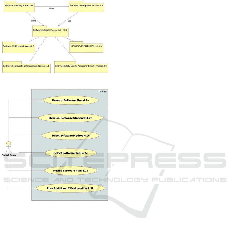
Figure 2: DO-168C UML Package-Level Representation.
Figure 3: DO-178C Software Planning Process 4.0 UML
Use Case Diagram Representation.
The second area of work with the DO-178C
specification is the definition of a model-driven
software development methodology that incorporates
and is compliant with the DO-178C requirements.
This methodology is illustrated in Figure. 4 in the
form of an UML activity diagram. Figure 4 is an
UML activity diagram representation of the
requirement-level activities contained in the Software
Development Process 5.0 package of Figure 2. The
activities of Figure 4 are mapped to the respective
sections of the DO-178C document, by way of the
DO-178C section number being listed in the activities
of the model. Figure 4 captures the activities as
specified in the DO-178C for the software
requirements analysis and design phases; the software
implementation (coding), testing, and deployment
phases are represented in separate UML activity
diagrams. The work reported on in this manuscript is
limited to the scope of Figure 4. The UML models
specified in Figure. 4 are specific to this instantiation
of the methodology; in other instantiations, other
models may be used to satisfy the requirements of
either the problem domain or the expertise of the
development team.
A first task requirement of DO-178C Software
Planning Process (4.0) is the determination of the
software level of development. DO-178C specifies
five (5) levels of criticality, designated Level-A
through Level-E, with Level-A being the highest and
Level E the lowest. Once the software level has been
determined then DO-178C Software Development
Process (5.0) and Software Integral process (6.0 –
10.0) specify the required set of activities and data
element necessary for certification of the system that
is to be developed. The outputs of these activities are
the Software Plan (4.2a), Software Standard (4.2b),
Software Method (4.2c), and Software Tool (4.2c), as
listed in Figure 3. There may be Additional
Considerations, for the particular application domain.
2.3 The Pedagogy
A version of the Figure 4 methodology is included in
the curriculum of the software engineering
undergraduate course and a graduate-level formal
specification course in the computer science course at
UND. In the undergraduate-level course, students are
taught a number of software development
methodologies, and are required to develop a small
software system by using a minimal version of the
methodology of Figure 4. In a similar manner at the
graduate-level, the students are required to develop a
more complex system than that of the undergraduate-
level. An additional requirement, at the graduate-
level, is that the system is assumed to be at the DO-
178C criticality Level-A, thus necessitating the use of
rigorous system validation and verification (V&V)
techniques as an activity of the used development
methodology. These V&V activities are executed at
the Verify Low Level Design 6.3 and Verify Low
Level Design 6.3, of Figure 4. This formal
specification technique involves the derivation of Z
notation (Potter, 1996) representation of the UML
models that were developed of the system at the
activities of Conduct High Level Design 5.2.2 and
Conduct Low Level Design 5.2.2 of Fig. 4.
CSEDU 2018 - 10th International Conference on Computer Supported Education
182
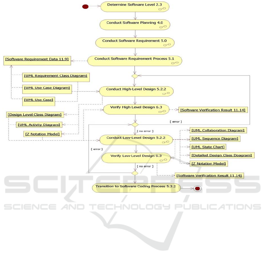
Figure 4: UML Activity Diagram Representation of DO-178C Compliant Model-Driven Methodology.
The software engineering courses are taught once
per year and follow a strict forward engineering
methodology approach. The topic of reverse
engineering is covered toward the end of the teaching
cycle, subject to the availability of lecture time;
teaching time on higher priority topics may be
extended thus reducing time for the lower priority
topics.
A review of the software engineering programs at
ten major universities in the USA, did not encounter
the term “reverse engineering” as ether a topic or
course in any of the listings. Search of the catalogue
of a major USA academic publishing firm for
textbooks on reverse engineering produced a hit list
of four items; similar searches for the terms
“requirement engineering”, “software design” and
“code generation” produces kit lists close to or
exceeding 100 items. These observations imply that
the topic of reverse engineering is not as widely
taught and written about in academia as are the other
phases of the software development life cycle.
3 PROJECT DESCRIPTION
At the start of the project, the Department of
Computer Science researchers formed three teams.
One team focused on developing the genetic
algorithms to implement the aircraft-to-gate
assignment solution. The second team focused on the
design and implementation of the user interface of the
system. The third team focused on the documentation
of the system, by way of modelling and
verification/validation exercises. The teams are
hereinafter referred to as Team I, Team II, and Team
III respectively. The content of this report is a
documentation of the efforts of Team III on project.
Notwithstanding the fact that the teams worked
independent of each other, to a great degree, there was
a high level of integration between the teams, as
Team II worked on the interface to the genetic
algorithms and Team III developed models of both
systems for verification and validation, and system
documentation. A secondary goal of Team III was
the identification and capture of any pedagogical
Pedagogical Benefits from an Exercise in Reverse Engineering for an Aviation Software Systems
183
principles for incorporation into the curricula of
software engineering courses, taught by the
Department of Computer Science.
The teams held joint and separate interviews with
the airline’s stakeholders; namely managers, system
administrators, and operators over the life of the
project, and typically had greater number of meetings
at the start and end of the project. Meetings at the
start of the project were geared towards capturing the
full requirements of the system, while meetings
towards the end of the project were targeted at system
verification and acceptance. At the initial phase of
the project, the teams sought to establish a common
set of system requirements, coming out of their
respective independent and joint meetings with the
stakeholders. Once these requirements were
finalized, the teams progressed at different rates of
work during the early stages of the project. In joint
meetings between the teams, Team III determined
that their initial models of the system were not
synchronized with the work products of the other two
teams, as there were supplemental meetings with
some of the stakeholders and some requirements had
been modified, eliminated, or new ones introduced.
This realization led to Team III reorganizing their
standard approach to the model development
activities.
3.1 Modified Methodology
Research showed that many software development
projects fail because of the inability to deliver the
product in a timely and cost effective manner, i.e. the
software crisis. Paul Dorsey list ten reasons why
systems projects fail (Dorsey, 1998). Among the
Dorsey’s list is the lack of use of an appropriate
software development methodology and focusing the
development efforts on coding. Teams I and II had
initiated what may be best described as an Agile
approach to developing the system’s user interface
and generic algorithm solutions, as they rapidly
produce coded components of the system. The teams
refined the code, after consultation with the
stakeholders, towards having a working system at the
earliest.
Team III ascertained that the initial strategy for
modelling the system would not be successful; hence,
the team modified the development methodology in
use to accommodate the work of the other two teams.
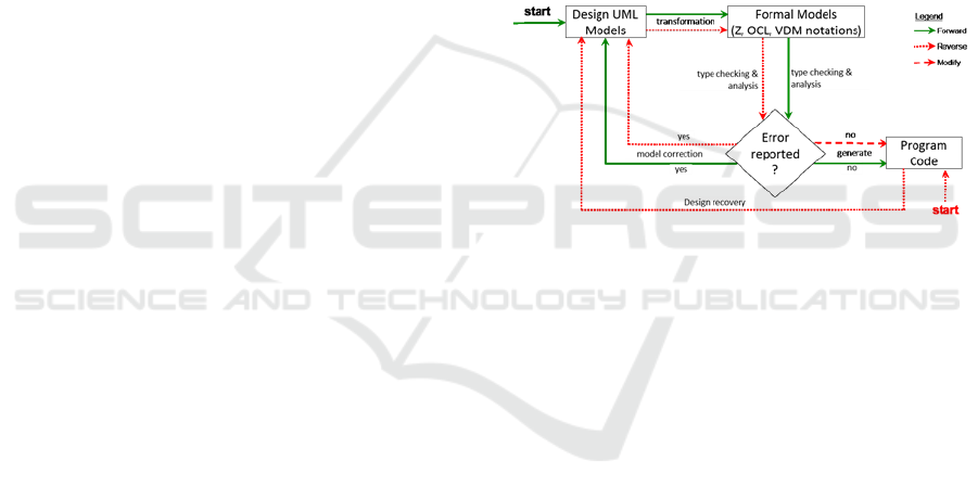
This modification was an iterative reverse
engineering process that is illustrated in Figure 5
The process model of Figure 5 was developed to
incorporate
a reverse-engineering strategy to
complete the forward-engineering activities. This
process model also illustrates the use of formal
specification techniques for validating the reverse and
forward engineering activities. The “Design UML
Models” activity of Figure 5 is reflective of the
Conduct High Level Design 5.2.2” and “Conduct
Low-Level Design 5.2.2” of Figure. 4, and the
“Formal Models” activity of Figure 5 is synonymous
to the “Verify High Level Design 6.3” and “Verify
Low-Level Design 6.3” activities of Figure 4. The
green (solid) arrowed lines represent the forward
engineering path through the process model, while
the red (broken) arrowed lines represent the reverse
engineering path through the model. The forward
engineering process commenced with the “Design
UML Models” activities, while the reverse
engineering process commenced at the “Program
Code” activity.
Figure 5: Reverse-Engineering Modified Model-Driven
Methodology.
This modification to the development
methodology then transitioned along the reverse
engineering line “Design recovery” line, from the
“Program Code” to representative “Design (high and
low) UML Models”. The UML models were then
transformed to a formal representation in the Z
notation for analysis during the verification phases of
the Figure 4 methodology. If the models pass the
verification, then work transition along the “generate”
arrowed lines to the production of “Program Code”.
Otherwise, work transition along the “model
correction” arrowed line to the UML models and the
next iteration of the process commence with the
identified errors being corrected in the models.
3.2 Project Implementation
Team I developed an acceptable generic algorithm
solution for the airline-gate assignment problem by
pursuing an Agile based methodology. The team held
monthly meetings with the airline’s stakeholder
managers and operators to present the accomplished
goals and establish a new set of goals for the next
CSEDU 2018 - 10th International Conference on Computer Supported Education
184
scheduled meeting. Visits were alternated between
the airline’s operation facility and UND research labs.
Each iteration resulted in the refinement of achieved
goals, accomplishment of established goals, or the
definition of new goals. While these sprints were
unusually long for a Scrum framework, they proved
adequate for this particular domain, because of the
complexity of the requirements and the development
strategy. Shorter sprints would have produced
incomplete goals at the level of granularity that would
be understandable to the stakeholders. Team I was
successful in completing a genetic algorithm
application system that was acceptable to the
stakeholders. The software system emulated the
actions of resolving aircraft-gate assignments in an
optimal manner that was equal to or better than that
which the experience operator could devise. This
ensured that even in the absence of an operator the
aircraft-gate assignment conflict resolution would be
completed in a timely manner for the airlines
operations.
Team II’s effort to develop a user interface for the
gate-assignment conflict resolution system, was
simplified after it was determined that the existing
user interface had to undergo minor modifications to
accommodate the new system. The modifications
involved adding a menu item for executing the
aircraft-gate assignment conflict-resolution system.
Consequently, the modelling of the user interface
system was not conducted by Team III, as the existing
documentation for the user interface was assessed to
be sufficient for the airlines system administrators.
3.3 Team Iii Efforts
Team III effort was centred on that of reverse
engineering a set of UML models of the genetic
algorithm system for the purpose of verification,
validation, and system documentation. Team III
opted to identify this system as a Level-A DO-178C
system, in order to exercise as many of the model-
driven methodology’s activities, as represented in
Figure 4. The intent was to garner as much
pedagogical benefits as possible for incorporation
into the software engineering curricula of the
department and provide comprehensive system
documentation artefact to the stakeholders.
The main UML model developed by Team III was
a set of activity diagrams that was implemented at the
detailed-level of system modelling. The limitation to
producing just one type of UML model was borne out
of the airline system administrators’ preference for
just the necessary models to facilitate any immediate
small-scale bug fixes, versus models to be used for
system evolution. The nature of the contract between
UND and the airline called for the software system’s
on-going maintenance (evolution) to be further
contracted out to a third party.
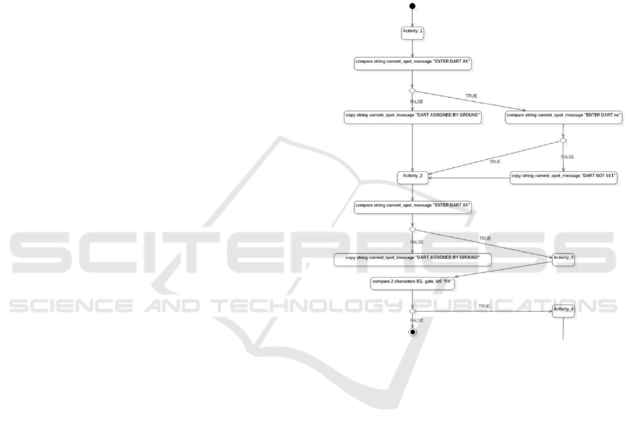
A sanitized example of a segment of one of the
UML activity diagrams that was developed is
presented in Figure. 6. Figure 6 does not illustrate any
significantly unusual activity diagram modelling
technique, but with the exception of the listing of
some activities with generic titles, such as “Activity
1”, “Activity 2”, etc.
Figure 6: UML Activity Diagram of Aircraft-Gate
Assignment System.
This was done in order to capture very low-level
details of the program code, from which the model
was reversed engineered.
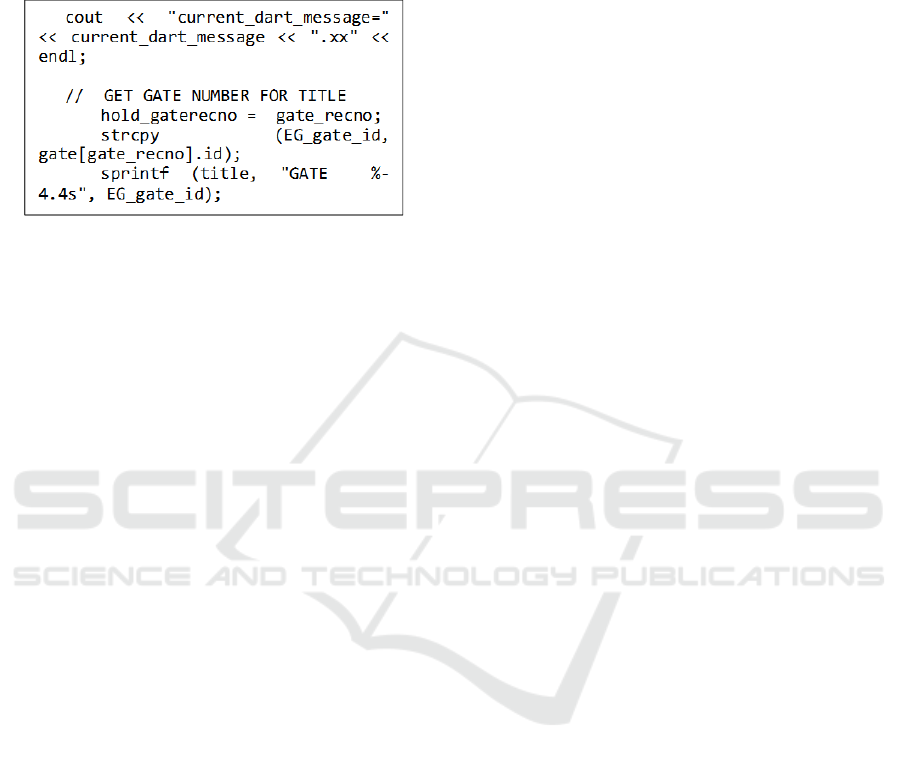
The models were developed in the open-source
tool StarUML and the contents of “Activity-Xs” were
stored in the documentation fields of the models. As
implemented in this activity diagram, “Activity 2” is
the snippet of code presented in Figure 7
Team I did not implement a fully object-oriented
programming paradigm, but partitioned the code-
production exercise into modules based on four
phases of the operation; (1) list aircrafts and terminal
gates, (2) assign aircrafts to gates, (3) generate
conflicts, and (4) resolve conflicts. Team III
completed the reverse engineering of the models with
the assistance of graduate students in the department,
under the supervision of faculty researchers. The
work was completed over one and one half years.
Pedagogical Benefits from an Exercise in Reverse Engineering for an Aviation Software Systems
185
Team III’s work was partitioned into two phases; the
first phase covers the reverse engineering of the UML
activity diagram models, and the second, future,
phase will involve the formal verification of the
models.
Figure 7: Code Snippet from UML Activity Diagram.
4 RESULT
Software system performance must always be
deterministic in the domain of safety-critical systems.
These software systems encompass numerous highly
complex processing components and have high
demands for reliability and accuracy, in order to
safeguard against failure.
Because of the extensive use of UML in software
development, there is a need to restate the informal
semantics of the models produces. Transforming
UML models into Z equivalent schemas provides
formal analysis to accomplish verification and
validation of software systems Clachar, 2010). With
the ever-growing demand for software systems in
existing, new, and emerging application areas, strict
requirements and design phase activities of software
development methodologies are sometimes not
enforced. Consequently, industrial practices
incorporate reverse engineering as a necessary phase
of software system development. This is done in
order to capture the necessary software system
modelling artefacts for system documentation and
maintenance.
In many USA universities, reverse engineering is
normally taught as an “add-on” to software
development methodologies. The resulting situation
is that graduates leave these software engineering
programs with minimal knowledge about reverse
engineering then find themselves in a work
environment where reverse engineering is of
paramount importance. The experience of the faculty
researchers on the project documented in this report,
and from a prior project on the development of an
UAS airworthiness system for monitoring UAVs
operation in a restricted airspace, is that there needs
to be a change in the pedagogical approach to
teaching reverse engineering.
The student researchers on this project and a prior
project, in which reverse engineering was also
applied, expressed specific and strong opinions on the
need to be taught formal approaches to reverse
engineering. Some of these student researchers had
participated in internship programs at a variety of
industrial organizations and had been exposed to
reverse engineering tasks. There was a unanimous
conclusion that reverse engineering is important to
the software development activities in real-world
project and consequently, they think the process
should be offered in courses on the same level as
forward engineering topics. There was also a
consensus among the student researchers that
working with code at the start of the project was
challenging and this challenge may be alleviated if
they had grounding in techniques to re-construct the
code.
The faculty researchers are now revising the
curricula of two undergraduate-levels and one
graduate-level courses in software engineering, at the
UND Department of Computer Science, to address
this identified disconnect between industrial practice
and the pedagogy. The curricula revision is multi-
faceted, with changes in lecture content, assignments,
and project requirements at both the undergraduate
and graduate levels of teaching. Selection of chapters
and articles from textbooks and journals on reverse
engineering will be listed for reference reading to
both groups of students, with some being selected as
required reading for each of the two groups. It should
be noted that while there is an abundance of textbooks
on forward engineering (requirements engineering,
software design, and software implementation) there
are less known and available textbooks on reverse
engineering, which are suitable for academia.
Assignments and projects will now include specific
work on reverse engineering in a form that is based
on the experience from the aforementioned two
projects. Critical to the new reverse engineering
pedagogy will be an emphasis on Agile software
development methodologies as a class of
methodologies that fosters the incorporation of
reverse engineering techniques.
4.1 The Revised Curriculum
The revised software engineering curriculum will
continue to be project-based, but will now include
activities in reverse engineering. The software
engineering methodology of instruction for the course
CSEDU 2018 - 10th International Conference on Computer Supported Education
186

will be based on the work defined in figures 4 and 5
of this report and the specific pedagogical topics
covered are influenced from the experience on the
aforementioned projects. Specifically, students will
be introduced to the relationship between forward and
reverse engineering, as illustrated in Figure 5.
Reverse engineering topics to be covered in the
revised curriculum include, but are not limited to the
following:
• Use of CASE tools in reverse engineering.
Specifically, open source tools will be used,
example StarUML, so that students can work
on their one computers.
• Reverse engineering techniques for object-
oriented programming versus procedural
programming.
• Techniques to manually reverse engineer
program codes that include: identifying
methods’ names, methods’ inputs and outputs,
and call sequences between methods.
• Techniques to identify programming
constructs, such as: assignments, iterations,
decisions, selections, etc.
• Techniques for transforming programming
code into pseudo-code.
• Techniques for transforming pseudo-code into
graphical models, namely UML models.
The teaching strategy applied in the revised
curriculum will have the students working in teams to
develop a moderately complex system as a forward
engineering exercise. Concurrently, the teams will
work on reverse engineering the code of a well-
known simple textbook system, such as the library
management system (Singh 2010). Both project will
be preceded by lectures on the fundamental principles
of software engineering, and concurrent lectures on
detailed and supplemental software engineering
topics. Pre- and post-surveys to determine the
students’ comprehension of the relationship between
academia and professional software engineering
learning and practices will be conducted. The data
from these surveys will aid in improving the
curriculum.
5 CONCLUSIONS
This report documents the experience gained from a
collaborative project between academia and industry
for developing a mission-critical software system,
albeit, the system was assessed as a safety-critical
application for educational purposes. The project was
conducted by teams of USA academic faculty and
student researchers, in difference spheres of focus.
One team conducted a reverse engineering exercise in
order to develop a set of graphical UML models, from
the program code of the system. These models
formed the main artefacts of documentation and
verification of the software system. This team had an
adjacent project goal of identifying aspects of the
project that would be incorporated in the curricula of
software engineering courses.
The project successfully achieved the established
goal by providing a software system to the
stakeholders that was introduced into production
within the specified timeframe. The adjacent project
goals of identifying pedagogical benefits from the
project were realized, as the hypothesis of a
knowledge gap existence between the curricula of
some USA undergraduate and graduate tertiary
software engineering education and industrial
practices was exemplified and data collected to
address this issue. The outcome is that the curricula
of these aforementioned courses have been revised to
include the teaching of reverse engineering as a first-
class topic of the courses under review. Future work
will seek to evaluate the benefits of this revised
pedagogy to the productivity of the graduates from
the courses. Future alumni surveys will include
specific questions to assess these benefits.
REFERENCES
Coad, P., Yourdon, E., 1991. Object-Oriented Design,
Prentice Hall, Inc. New Jersey, USA.
Shlaer, S., Mellor, S. J., 1988. Object Oriented Systems
Analysis: Modeling the World in Data, 1
st
ed., Prentice
Hall, New Jersey, USA.
Glass, R. L., 1997. The Software-Research Crisis, IEEE
Software, IEEE Computer Society Press, California,
USA, vol. 11. No. 6, pp, 42-47.
Booch, G., Rumbaugh, J., Jacobson, I., 1997. The Unified
Modeling Language, Rational Software Corporation,
Addison-Wesley, Indiana, USA.
Kruchten, P. 2003 The Rational Unified Process: An
Introduction, 3
rd
ed., Addison-Wesley Object
Technologies Series, Indiana, USA.
Leveson, N. G., Turner, C. S., 1993. An Investigation of the
Therac-25 Accidents, IEEE Computer, IEEE Computer
Society, vol. 26, No. 7, pp 18-41.
Lions, J., 1996 ARIANE 5, Flight 501 Failure, Report by
the Inquiry Board, European Space Agency, Paris,
France.
Bureau d’Enquêtes et d’Analyses, 2012, Final Report on
the Accident on 1st June 2009 to the Airbus A330-203
Registered F-GZCP operated by Air France flight AF
447 Rio de Janeiro – Paris, Bureau d'Enquetes et
d'Analyses France (BEA), Paris, France.
Pedagogical Benefits from an Exercise in Reverse Engineering for an Aviation Software Systems
187

RTCA, 2011. Software Considerations in Airborne Systems
and Equipment Certification. DO-178C, Radio
Technical Commission for Aeronautics (RTCA),
Washington DC, USA.
Potter, B., Sinclair, J., Till, D., 1996. An Introduction to
Formal Specification and Z, 2
nd
ed., Prentice Hall
Europe, Hertfordshire, UK.
Clachar, S., Grant, E. S., 2010. A Case Study in Formalizing
UML Software Models of Safety Critical Systems, The
Annual International Conference on Software
Engineering. Global Science and Technology Forum
(GSTF), Phuket, Thailand.
Dorsey, P., 1998. 10 Reasons Why Systems Projects Fail,
Technical Report, Dulcian, Inc.
Singh, D., 2010, C++ Library Management System
Project - Source Code of Program, CPPforschool C++
Tutorial for School Students, Ghaziabad, India.
CSEDU 2018 - 10th International Conference on Computer Supported Education
188
